STA5620
Fully integrated RF front-end receiver for GPS applications
Features
■
Low IF architecture (fIF = 4fO)
■
Minimum external components
■
VGA gain internally regulated
■
On chip programmable PLL
■
Typ. 2.7 V supply voltage
■
SPI interface
■
2 kV HBM ESD protected
■
Compatible with GPS L1
■
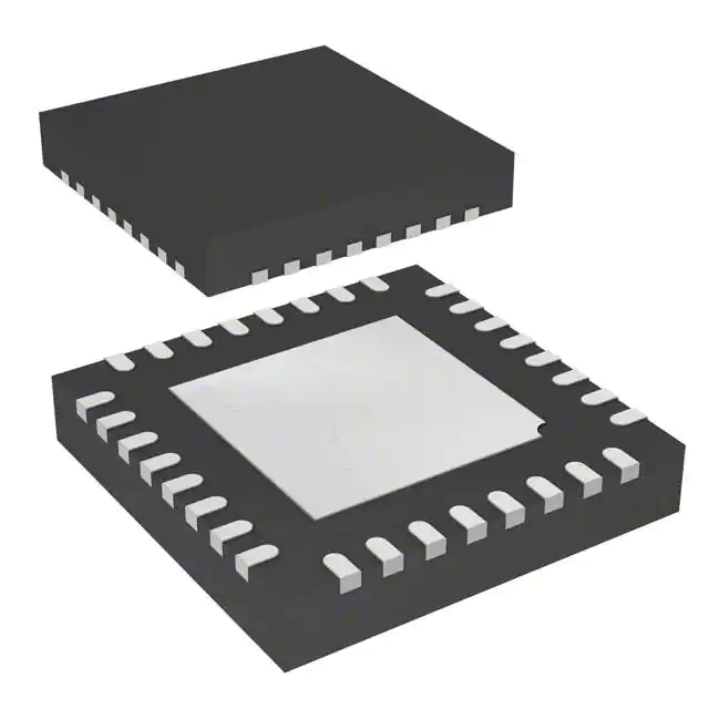
Standard QFN-32 package
■
Low power for portable designs
u
d
o
VFQFPN32
r
P
e
t
e
l
o
The magnitude data is internally integrated in
order to control the variable gain amplifiers in
accordance to the RF input signal strength.
Description
)
(s
The chip is a fully integrated RF front-end able to
down-convert the GPS L1 signal from
1575.42 MHz to 4.092 MHz.
t
c
u
The IF signal is converted by a two bit ADC. Sign
(SIGN), Magnitude (MAG) and the 16.368 MHz
sampling clock (GPS_CLK) are provided to the
baseband.
d
o
r
P
e
t
e
l
o
Table 1.
s
b
O
)
s
(
ct
s
b
O
An excellent quality of reception in critical
environments is ensured by the good noise figure
and linearity of the receiver.
The on-chip oscillator supports crystal
frequencies in the range of 10MHz to 40MHz. It is
able to support TCXO providing also a buffered
copy of the oscillator frequency.
The chip, using STMicroelectronics BiCMOS
SiGe technology, is housed in a QFN-32 package.
Device summary
Order code
Marking
Package
Packing
STA5620TR
STA5620
VFQFPN32
Tape & reel
February 2008
Rev 4
1/29
www.st.com
1
�Contents
STA5620
Contents
1
Block diagram . . . . . . . . . . . . . . . . . . . . . . . . . . . . . . . . . . . . . . . . . . . . . . 6
2
Pins description . . . . . . . . . . . . . . . . . . . . . . . . . . . . . . . . . . . . . . . . . . . . 7
3
Functional description . . . . . . . . . . . . . . . . . . . . . . . . . . . . . . . . . . . . . . . 9
4
2/29
3.2
IF section . . . . . . . . . . . . . . . . . . . . . . . . . . . . . . . . . . . . . . . . . . . . . . . . . . 9
3.3
Variable gain amplifiers . . . . . . . . . . . . . . . . . . . . . . . . . . . . . . . . . . . . . . . 9
3.4
A/D converter . . . . . . . . . . . . . . . . . . . . . . . . . . . . . . . . . . . . . . . . . . . . . . . 9
3.5
PLL synthesizer and VCO . . . . . . . . . . . . . . . . . . . . . . . . . . . . . . . . . . . . 10
3.6
Crystal oscillator . . . . . . . . . . . . . . . . . . . . . . . . . . . . . . . . . . . . . . . . . . . . 10
3.7
Output buffers . . . . . . . . . . . . . . . . . . . . . . . . . . . . . . . . . . . . . . . . . . . . . . 10
3.8
SPI interface . . . . . . . . . . . . . . . . . . . . . . . . . . . . . . . . . . . . . . . . . . . . . . . 10
3.9
Power control modes . . . . . . . . . . . . . . . . . . . . . . . . . . . . . . . . . . . . . . . . 11
)
s
(
ct
u
d
o
r
P
e
t
e
l
o
)
(s
s
b
O
4.1
Absolute maximum ratings . . . . . . . . . . . . . . . . . . . . . . . . . . . . . . . . . . . . 12
4.2
Thermal data . . . . . . . . . . . . . . . . . . . . . . . . . . . . . . . . . . . . . . . . . . . . . . 12
4.3
Electrical characteristics . . . . . . . . . . . . . . . . . . . . . . . . . . . . . . . . . . . . . . 12
t
c
u
d
o
r
P
e
Pin and I/O cells . . . . . . . . . . . . . . . . . . . . . . . . . . . . . . . . . . . . . . . . . . . . 15
t
e
l
o
s
b
O
7
RFA and MIXER section . . . . . . . . . . . . . . . . . . . . . . . . . . . . . . . . . . . . . . . 9
Electrical specifications . . . . . . . . . . . . . . . . . . . . . . . . . . . . . . . . . . . . . 12
5
6
3.1
5.1
Mode . . . . . . . . . . . . . . . . . . . . . . . . . . . . . . . . . . . . . . . . . . . . . . . . . . . . 15
5.2
RF_EN . . . . . . . . . . . . . . . . . . . . . . . . . . . . . . . . . . . . . . . . . . . . . . . . . . . 15
5.3
CHIP_EN . . . . . . . . . . . . . . . . . . . . . . . . . . . . . . . . . . . . . . . . . . . . . . . . . 15
5.4
TEST_EN1, TEST_EN2 and TEST_CLK . . . . . . . . . . . . . . . . . . . . . . . . . 15
SPI bus protocol . . . . . . . . . . . . . . . . . . . . . . . . . . . . . . . . . . . . . . . . . . . 16
6.1
SPI_CS/ . . . . . . . . . . . . . . . . . . . . . . . . . . . . . . . . . . . . . . . . . . . . . . . . . . 16
6.2
SPI_CLK . . . . . . . . . . . . . . . . . . . . . . . . . . . . . . . . . . . . . . . . . . . . . . . . . 16
6.3
SPI_DI . . . . . . . . . . . . . . . . . . . . . . . . . . . . . . . . . . . . . . . . . . . . . . . . . . . 16
6.4
SPI_DO . . . . . . . . . . . . . . . . . . . . . . . . . . . . . . . . . . . . . . . . . . . . . . . . . . 16
Registers . . . . . . . . . . . . . . . . . . . . . . . . . . . . . . . . . . . . . . . . . . . . . . . . . 17
�STA5620
8
Contents
7.1
Register map . . . . . . . . . . . . . . . . . . . . . . . . . . . . . . . . . . . . . . . . . . . . . . 17
7.2
PLL N divider . . . . . . . . . . . . . . . . . . . . . . . . . . . . . . . . . . . . . . . . . . . . . . 17
7.3
PLL R divider . . . . . . . . . . . . . . . . . . . . . . . . . . . . . . . . . . . . . . . . . . . . . . 17
7.4
Radio configuration register . . . . . . . . . . . . . . . . . . . . . . . . . . . . . . . . . . . 18
7.5
Test register . . . . . . . . . . . . . . . . . . . . . . . . . . . . . . . . . . . . . . . . . . . . . . . 18
7.6
Debug register (sub-circuit enables) . . . . . . . . . . . . . . . . . . . . . . . . . . . . 19
7.7
Radio trimming register . . . . . . . . . . . . . . . . . . . . . . . . . . . . . . . . . . . . . . 20
7.8
Receiver chain register (enable) . . . . . . . . . . . . . . . . . . . . . . . . . . . . . . . 20
)
s
(
ct
Chip enable and reset timing . . . . . . . . . . . . . . . . . . . . . . . . . . . . . . . . . 21
8.1
Principle of operation . . . . . . . . . . . . . . . . . . . . . . . . . . . . . . . . . . . . . . . . 21
8.1.1
8.2
u
d
o
Operating modes . . . . . . . . . . . . . . . . . . . . . . . . . . . . . . . . . . . . . . . . . . 22
r
P
e
Default configuration . . . . . . . . . . . . . . . . . . . . . . . . . . . . . . . . . . . . . . . . 23
t
e
l
o
9
Package information . . . . . . . . . . . . . . . . . . . . . . . . . . . . . . . . . . . . . . . . 25
10
Packing information . . . . . . . . . . . . . . . . . . . . . . . . . . . . . . . . . . . . . . . . 26
11
Revision history . . . . . . . . . . . . . . . . . . . . . . . . . . . . . . . . . . . . . . . . . . . 28
)
(s
s
b
O
t
c
u
d
o
r
P
e
t
e
l
o
s
b
O
3/29
�List of tables
STA5620
List of tables
Table 1.
Table 2.
Table 3.
Table 4.
Table 5.
Table 6.
Table 7.
Table 8.
Table 9.
Table 10.
Table 11.
Table 12.
Table 13.
Table 14.
Table 15.
Table 16.
Device summary . . . . . . . . . . . . . . . . . . . . . . . . . . . . . . . . . . . . . . . . . . . . . . . . . . . . . . . . . . 1
Pins list description . . . . . . . . . . . . . . . . . . . . . . . . . . . . . . . . . . . . . . . . . . . . . . . . . . . . . . . . 7
Absolute maximum ratings . . . . . . . . . . . . . . . . . . . . . . . . . . . . . . . . . . . . . . . . . . . . . . . . . 12
Thermal data. . . . . . . . . . . . . . . . . . . . . . . . . . . . . . . . . . . . . . . . . . . . . . . . . . . . . . . . . . . . 12
Electrical characteristics . . . . . . . . . . . . . . . . . . . . . . . . . . . . . . . . . . . . . . . . . . . . . . . . . . . 12
Register map . . . . . . . . . . . . . . . . . . . . . . . . . . . . . . . . . . . . . . . . . . . . . . . . . . . . . . . . . . . 17
PLL N divider . . . . . . . . . . . . . . . . . . . . . . . . . . . . . . . . . . . . . . . . . . . . . . . . . . . . . . . . . . . 17
PLL R divider . . . . . . . . . . . . . . . . . . . . . . . . . . . . . . . . . . . . . . . . . . . . . . . . . . . . . . . . . . . 17
Radio configuration register . . . . . . . . . . . . . . . . . . . . . . . . . . . . . . . . . . . . . . . . . . . . . . . . 18
Test register . . . . . . . . . . . . . . . . . . . . . . . . . . . . . . . . . . . . . . . . . . . . . . . . . . . . . . . . . . . . 18
Debug register (sub-circuit enables) . . . . . . . . . . . . . . . . . . . . . . . . . . . . . . . . . . . . . . . . . . 19
Radio trimming register. . . . . . . . . . . . . . . . . . . . . . . . . . . . . . . . . . . . . . . . . . . . . . . . . . . . 20
Receiver chain register (enable) . . . . . . . . . . . . . . . . . . . . . . . . . . . . . . . . . . . . . . . . . . . . . 20
Operating modes . . . . . . . . . . . . . . . . . . . . . . . . . . . . . . . . . . . . . . . . . . . . . . . . . . . . . . . . 22
Default configuration . . . . . . . . . . . . . . . . . . . . . . . . . . . . . . . . . . . . . . . . . . . . . . . . . . . . . . 23
Document revision history . . . . . . . . . . . . . . . . . . . . . . . . . . . . . . . . . . . . . . . . . . . . . . . . . 28
)
s
(
ct
u
d
o
r
P
e
t
e
l
o
)
(s
t
c
u
d
o
r
P
e
t
e
l
o
s
b
O
4/29
s
b
O
�STA5620
List of figures
List of figures
Figure 1.
Figure 2.
Figure 3.
Figure 4.
Figure 5.
Figure 6.
Figure 7.
Figure 8.
Figure 9.
Block diagram . . . . . . . . . . . . . . . . . . . . . . . . . . . . . . . . . . . . . . . . . . . . . . . . . . . . . . . . . . . . 6
Pins connection diagram (bottom view) . . . . . . . . . . . . . . . . . . . . . . . . . . . . . . . . . . . . . . . . 8
SPI byte write . . . . . . . . . . . . . . . . . . . . . . . . . . . . . . . . . . . . . . . . . . . . . . . . . . . . . . . . . . . 16
SPI byte read . . . . . . . . . . . . . . . . . . . . . . . . . . . . . . . . . . . . . . . . . . . . . . . . . . . . . . . . . . . 16
Chip enable and reset timing . . . . . . . . . . . . . . . . . . . . . . . . . . . . . . . . . . . . . . . . . . . . . . . 21
VFQFPN32 (5x5x1.0 mm) mechanical data and package dimensions . . . . . . . . . . . . . . . 25
Reel, leader and trailer dimensions . . . . . . . . . . . . . . . . . . . . . . . . . . . . . . . . . . . . . . . . . . 26
Carrier tape requirements . . . . . . . . . . . . . . . . . . . . . . . . . . . . . . . . . . . . . . . . . . . . . . . . . . 27
Orientation . . . . . . . . . . . . . . . . . . . . . . . . . . . . . . . . . . . . . . . . . . . . . . . . . . . . . . . . . . . . . 27
)
s
(
ct
u
d
o
r
P
e
t
e
l
o
)
(s
s
b
O
t
c
u
d
o
r
P
e
t
e
l
o
s
b
O
5/29
�Block diagram
1
STA5620
Block diagram
Figure 1.
Block diagram
AGC_CTRL
RF chain
IF_TEST
IFB
IR Mixer
IF filter
SIGN
RFA
RF_IN
AGC
2
bits
ADC
Combiner
MAG
Polyphase
Filter
mag
Buffer
mag
)
s
(
ct
GCE & RFE
0˚
90˚
CP
/ 48
SPI_CS/
SPI_CLK
SPI
Interface
SPI_DI
SPI_DO
xtal_clk
)
(s
t
c
u
d
o
r
P
e
6/29
r
P
e
Reset
Generator
t
e
l
o
s
b
O
CHIP_EN
LO96
/2
reset
MODE
RF_EN
s
b
O
GPS_CLK
GCE
Test
Logic
TEST_CLK
t
e
l
o
u
d
o
/R
/N
TEST_EN1
TEST_EN2
CMOS Drivers
PFD
MST
Xtal
XTAL_CLK
xtal_clk
XO
Xtal Osc
XI
XCE
AC00324
�STA5620
2
Pins description
Pins description
Table 2.
PIN
Symbol
1
VCC
2
AGC_CTRL
3
VCC
4
RF_IN
5
VCC
RF amplifier power supply
6
GND
Negative Supply Pin
7
GND
Negative Supply Pin
8
VCC
Charge pump power supply
9
VCC
Digital section power supply
10
VCC
VCO power supply
11
VCC
Crystal oscillator power supply
12
XTAL_IN
13
XTAL_OUT
Output Side of Crystal Oscillator
14
TEST_EN1
Test enable 1. Only for ST internal use
Digital – input
15
CHIP_EN
Chip Enable
Digital – input
16
RF_EN
17
MODE
18
XTAL_CLK
Description
Type
IF section power supply
Supply pin
Automatic Gain Control Pin
Analog – input
Mixer power supply
Supply pin
RF section input
Analog – RF input
Supply pin
)
s
(
ct
Gnd
u
d
o
Supply pin
e
t
e
l
Pr
so
Input Side of Crystal Oscillator or TCXO Input
)-
b
O
s
(
t
c
u
d
o
Gnd
Supply pin
Supply pin
Supply pin
Analog – input
Analog – output
RF/IF Receiver Chain Enable
Digital – input
Power-On Default Configuration Selector
Digital – input
Crystal Oscillator Buffered Output
Digital – output
GPS_CLK
GPS Reference Clock
Digital – output
TEST_CLK
Test Clock. Only for ST internal use
Digital – output
21
TEST_EN2
Test enable 2. Only for ST internal use
Digital – input
22
SPI_DI
Serial Parallel Interface Data Input
Digital – input
23
SPI_CLK
Serial Parallel Interface Clock
Digital – input
24
SPI_CS/
Serial Parallel Interface Chip Select (Active Low)
Digital – input
25
SPI_DO
Serial Parallel Interface Data Output
Digital – output
26
MAG
Magnitude Data
Digital – output
27
SIGN
Sign Data
Digital – output
28
GND_IO
Output Drivers Ground
29
VCC_IO
I/Os power supply
Supply pin
30
VCC
SPI power supply
Supply pin
31
VCC
A/D converter power supply
Supply pin
32
IF_TEST
19
20
e
t
e
ol
s
b
O
Pins list description
Pr
RF/IF Receiver Chain Test Output
Gnd
Analog – output
7/29
�Pins description
VCC
VCC
VCC
XTAL_IN
XTAL_OUT
TEST_EN1
CHIP_EN
RF_EN
Pins connection diagram (bottom view)
9
10
11
12
13
14
15
16
18
XTAL_CLK
GND
6
19
GPS_CLK
VCC
5
20
TEST_CLK
RF_IN
4
21
TEST_EN2
VCC
3
22
SPI_DI
AGC_CTRL
2
23
SPI_CLK
VCC
1
24
SPI_CS
31
30
29
28
27
26
o
s
b
let
O
)
s
(
t
c
u
d
o
r
P
e
t
e
l
o
s
b
O
8/29
)
s
(
ct
u
d
o
r
P
e
25
SPI_DO
32
MAG
7
SIGN
GND
GND_IO
MODE
VCC_IO
17
VCC
8
VCC
VCC
IF_TEST
Figure 2.
STA5620
AC00325
�STA5620
Functional description
3
Functional description
3.1
RFA and MIXER section
The 1575.42 MHz RF signal at the output of the external SAW filter is amplified by a RF
amplifier (RFA) and then down converted by an image rejection mixer.
The good performances of the cascade configuration and the technology choice guarantee
a noise figure better than 4.5 dB in typical conditions. In fact, the RFA gain is high enough to
minimize the effects on the noise figure of the following integrated stages.
The linearity of the RFA and Mixer section ensures immunity to RF blockers close to the
GPS signal. Then it allows the use of low quality external pre-selection filters.
)
s
(
ct
Two ninety degrees out of phase signals are derived from the VCO and send to the input of
the image rejection mixer. A minimum image rejection ratio of 20 dB is guaranteed.
u
d
o
The chosen IF frequency is 4fo = 4.092 MHz.
3.2
r
P
e
IF section
t
e
l
o
The output of the mixer combiner is processed through an integrated filter able to select the
GPS L1 bands. The IF filter cuts any out-of-band signal including the mixer products. In
addition it acts as an anti-aliasing filter for the A/D converter. An attenuation of 20 dB is
guaranteed at 12fo = 12.276 MHz.
)
(s
s
b
O
The IF filter characteristic is calibrated by an internal loop which compensates process,
temperature and voltage variations.
t
c
u
In order to let the baseband reconstruct the received information, the IF filter must not
introduce an excessive phase shift within the signal bandwidth.
d
o
r
3.3
Variable gain amplifiers
P
e
t
e
l
o
s
b
O
A cascade of variable gain amplifiers and the relevant control circuit balance the system
gain in relationship to the RF input signal strength. In that way the signal level at the input of
the A/D converter is suitably compensated.
The device is able to self-adjust the AGC gain by integrating the MAG output by a dedicated
circuit in order to obtain 33 % of MAG bit duty cycle. The loop is compensated by an
external capacitor connected to the AGC_CTRL pin. The relevant voltage is used to control
the variable gain amplifiers.
The internal loop can be by-passed by setting a voltage to the AGC_CTRL input pin. A
dynamic range of around 55 dB is typically achieved.
3.4
A/D converter
The task of the A/D converter is to determine the sign and the magnitude of the received
signal. The A/D converter sampling frequency is 16fo = 16.368 MHz.
Those baseband chips with just one bit input will use only the sign bit. In that case the
AGC_CTRL pin must be connected to ground through an external capacitor (~ 10 µF).
9/29
�Functional description
3.5
STA5620
PLL synthesizer and VCO
The PLL synthesizer is fully integrated on-chip, it is made by the voltage controlled oscillator
(VCO), prescaler, dividers, phase-frequency detector (PFD), charge pump (CP) and loop
filter. Both the reference divider R and the feedback divider N are programmable helping the
user to choose the reference clock. The R divider ranges from 1 to 63 while the N divider
from 56 to 4095.
In order to achieve good phase noise performances, a LC voltage controlled oscillator has
been chosen. Quadrature signals are provided by means of a polyphase filter.
A programmable loop filter is integrated on-chip to reduce the number of external
components. The loop stability is guaranteed for any of the supported crystals and
comparison frequencies.
)
s
(
ct
The charge pump is programmable and the output current can be selected among the
following values: 50 µA, 100 µA, 150 µA and 200 µA.
3.6
u
d
o
Crystal oscillator
r
P
e
The reference oscillator circuit is a CMOS inverter able to work with external crystals up to
40 MHz. The crystal must be connected between the xtal input and the xtal output pins. The
load capacitances must be chosen in accordance to the values specified by the crystal
manufacturer. A limiting resistor can be placed at the output of the inverter in order to
contain the power dissipated in the crystal within its specified maximum value.
t
e
l
o
s
b
O
When a TCXO is used the external reference clock must be applied to the XTAL_IN
terminal.
)
(s
t
c
u
3.7
Output buffers
d
o
r
The RF front-end provides a set of four different signals to the baseband chip.
The SIGN and the MAG outputs are the sampled bit streams of the down-converted
received signal.
P
e
t
e
l
o
s
b
O
3.8
GPS_CLK, nominally equal to 16.368 MHz, is the clock signal used by the baseband. Its
source can be chosen among the crystal oscillator signal and the VCO signal by means of a
96 divider.
XTAL_CLK is the buffered copy of either the crystal oscillator or the TCXO signal.
In order to let the application find the best compromise between electro-magnetic
interferences and the drivers speed, the output stages slew-rate can be programmed by
SPI.
SPI interface
A SPI interface manages the communication between the baseband chip and the RF frontend. Four lines are required to accomplish this task: a data input line (SPI_DI), a data output
line (SPI_DO), a clock line (SPI_CLK) and a chip select line (SPI_CS/) active low.
Any information can be passed to the RF receiver through the SPI interface depending on
the CHIP_EN and RF_EN input pins status.
10/29
�STA5620
3.9
Functional description
Power control modes
Three different power control modes can be chosen by means of the CHIP_EN and the
RF_EN pins. If the CHIP_EN pin is forced low the device goes to stand-by mode with very
low power consumption. On the other hand, if CHIP_EN is set high, two scenarios are
possible:
1.
IIf RF_EN = 0 the crystal oscillator and only one output buffer are enabled,
XTAL_CLK if MODE = 1 or GPS_CLK if MODE = 0;
2.
If RF_EN = 1 the whole chip is active and functional.
Only if MODE = 0 the XTAL_CLK output is disabled.
A logic reset of the SPI registers is generated by the low to high transitions of the CHIP_EN
pin. External pin strapping dominates until some SPI commands reverse the priority and
overrides the strapping until next reset.
)
s
(
ct
u
d
o
r
P
e
t
e
l
o
)
(s
s
b
O
t
c
u
d
o
r
P
e
t
e
l
o
s
b
O
11/29
�Electrical specifications
STA5620
4
Electrical specifications
4.1
Absolute maximum ratings
Table 3.
Absolute maximum ratings
Symbol
Parameter
Min
Max
Unit
All supply voltages
-0.3
3.6
V
TJ
Junction operating temperature
-40
125
°C
TS
Storage temperature
-65
150
°C
-
2
-
200
-
750
VCC
ESDHBM Electro static discharge – Human body model
Electro static discharge – Machine model
ESDMM
ESDCDM Electro static discharge - Charged device model
4.2
Thermal data
Table 4.
e
t
e
ol
Thermal data
Symbol
bs
Parameter
Ambient operating temperature
Tamb
O
)
Rth j-amb
Thermal resistance junction to ambient
V
du
V
o
r
P
Value
Unit
-40 to 85
°C
40
°C/W
s
(
t
c
4.3
Electrical characteristics
Table 5.
Electrical characteristics
(VCC = 2.7 V, TJ = 25 °C unless otherwise noted)
Symbol
u
d
o
r
P
e
Min
Typ
Max
Unit
Analog, Digital
2.56
2.7
3.3
V
I/O supply
1.7
3.3
V
t
e
l
o
Supply
bs
VCC
O
)
s
(
ct
kV
Vcc_IO
Parameter
Test conditions
Total power consumption
Internal blocks ON
15
19
mA
ICC_CLK
Clock only power consumption
Crystal oscillator ON
1.5
1.8
mA
ICC_STB
Stand-by power consumption
Internal blocks OFF
1
μA
1575.42
MHz
4.092
MHz
ICC
RFA – MIXER – IF FILTER – VGA
fIN
RFA Input frequency
fIF
IF frequency
GC
Conversion gain
12/29
VGA at max gain
105
VGA at min gain
50
dB
�STA5620
Table 5.
Electrical specifications
Electrical characteristics (continued)
(VCC = 2.7 V, TJ = 25 °C unless otherwise noted)
Symbol
ΔGC
Parameter
Test conditions
Set VAGC_CTRL < 0.3 V
for maximum gain
VGA range
VAGC_CTRL AGC Control Voltage Range
GSENS
P_1dB
IRR
-57
Mixer image rejection ratio
f = 2 to 6 MHz
20
)
s
(
ct
20
e
t
e
ol
XTAL frequency
Reference input signal sensitivity
Reference divider range
FLO
LO operating frequency
XTAL_IN pin DC
blocked.
No crystal mounted.
XTAL_OUT load
很抱歉,暂时无法提供与“STA5620TR”相匹配的价格&库存,您可以联系我们找货
免费人工找货