UM1059
User manual
The STPMC1 and STPMS2 evaluation kit
Introduction
The STEVAL-IPE014V1 is an evaluation board designed for the STPMS2L-PUR chip. It works along
with the STEVAL-IPE010V2 evaluation board, for a ready-to-use energy meter application.
The STEVAL-IPE010V2 evaluation board is for the STPMC1 device, while the STEVAL-IPE014V1
package contains the daughterboard with the STPMS2L-PUR companion chip.
These evaluation boards can be used in two ways:
For evaluation purposes. Connecting the reference design to an AC power source and changing all
setting parameters through the GUI interface and the parallel hardware programmer/reader
For user application evaluation and development
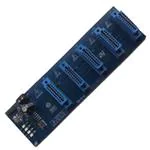
Figure 1: STEVAL-IPE010V2 evaluation board
Figure 2: STEVAL-IPE014V1 evaluation board
October 2014
DocID018518 Rev 2
1/9
www.st.com
�Contents
UM1059
Contents
1
2
Overview .......................................................................................... 3
1.1
Safety rules ....................................................................................... 3
1.2
Operating conditions ......................................................................... 3
1.3
Features ............................................................................................ 3
1.4
Recommended readings ................................................................... 4
1.5
Getting technical support .................................................................. 4
STEVAL-IPE014V1 components ..................................................... 5
2.1
Package content ............................................................................... 5
2.2
STEVAL-IPE014V1 ........................................................................... 5
2.2.1
3
4
2/9
Jumper settings .................................................................................. 5
Getting started ................................................................................. 7
3.1
Board connection .............................................................................. 7
3.2
System configuration ......................................................................... 7
Revision history .............................................................................. 8
DocID018518 Rev 2
�UM1059
Overview
1
Overview
1.1
Safety rules
This set of boards can be connected to mains voltage (220 V/110 V). In the case of
improper use, wrong installation or malfunction, there is a danger of serious personal injury
and damage to property. All operations such as: transport, installation, and commissioning,
as well as maintenance, should be carried out by skilled technical personnel only (national
accident prevention rules must be observed).
Due to the risk of death when this prototype on mains voltage (220 V/110 V) is used,
“skilled technical personnel” only, who are familiar with installation, mounting,
commissioning, and operating with power electronic systems and have the qualifications to
perform these functions, may use this prototype.
1.2
Operating conditions
Table 1: Operating conditions
1.3
Condition
Value
Unit
VNOM
230
VRMS
INOM
CT: INOM = 1
ARMS
IMAX
CT: IMAX = 30
ARMS
fLIN
50/60 ± 10%
Hz
TOP
-40 / +85
°C
Features
Modularity
Programmability
Supports:
3-phase, 4-wire RSTN, 4-system RSTN (tamper); extra module is needed
3-phase, 4-wire RSTN, 3-system RST
3-phase, 3-wire RST_, 3-system RST_ (tamper)
3-phase, 3-wire RST_, 2-system R_T_ (Aron)
2-phase, 3-wire _STN, 2-system _ST_ (America)
1-phase, 2-wire __TN, 2-system _ST_ (tamper)
1-phase, 2-wire __TN, 1-system __T_
4 LEDs showing:
Power
No load condition
Tamper detection
Reverse current direction
Embedded capacitive power supply
Isolation of current channel
DocID018518 Rev 2
3/9
�Overview
1.4
UM1059
Recommended readings
This document describes how to use and set up a basic test session with a GUI interface.
Further information can be found in the following documents:
1.5
STPMC1 datasheet
STPMS2 datasheet
Component datasheet
AN4121, AN3398 and AN3254 application notes
Schematics
Getting technical support
Technical assistance is provided free to all customers. For technical assistance,
documentation, information, and product upgrades and services, please refer to your local
ST distributor/office.
ST microelectronics offers its customers a free technical support service at online support
in the www.st.com web site. Before contacting us, we recommend checking that you are
working with the latest version of software/firmware. Upgrades are available free of charge
at http://www.st.com.
4/9
DocID018518 Rev 2
�UM1059
STEVAL-IPE014V1 components
2
STEVAL-IPE014V1 components
2.1
Package content
The package contains:
2.2
Number 1 STEVAL-IPE014V1
Promotional CD
STEVAL-IPE014V1
This board is a daughterboard. Each module serves one single phase, converting the
voltage and current information, multiplexing them together, and sending the stream to the
STPMC1.
Each of the boards must be connected to the voltage source of the relative phase and to
the load.
Test points available are:
GND
VCC (stepper counter display connector)
CLK
DAT
VREG
F, N
The board should be plugged into the motherboard by the edge connector. Voltage inputs
are pin F (hot wire) and N (neutral wire).
Current input (load wire) should be passed through the current transformer placed on the
non-component side of the module.
2.2.1
Jumper settings
The onboard jumpers JP1, JP2, JP3, and JP4 allow the setting of the STPMS2L-PUR
device according to Table 2: "Precision mode and input amplifier gain selection", Table 3:
"TC of the bandgap reference", Table 4: "Control of voltage channel and output signals"
and Table 5: "Selection of hard, soft or test mode and enable of BIST" below:
Table 2: Precision mode and input amplifier gain selection
JP1
MS0
Description
1
GND
LPR, amplifier GAIN selection g3 = 16
2
CLK
LPR, amplifier GAIN selection g0 = 2
3
NCLK
HPR, amplifier GAIN selection g0 = 2
VCC
HPR, amplifier GAIN selection g3 = 16
4
(1)
Notes:
(1)
Default value
DocID018518 Rev 2
5/9
�STEVAL-IPE014V1 components
UM1059
Table 3: TC of the bandgap reference
JP2
MS1
Description
1
GND
TC = 60 ppm/°C
2
(1)
CLK
Flattest TC = +30 ppm/°C
3
NCLK
TC = +160 ppm/°C
4
VCC
TC = -160 ppm/°C
Notes:
(1)
Default value
Table 4: Control of voltage channel and output signals
JP3
MS2
Description
(1)
GND
Voltage channel ON, DATn = ~(DAT =(CLK) ? bsV: bsC
2
CLK
Voltage channel OFF, DATn = bsCn, DAT = bsC
3
NCLK
Voltage channel OFF, DATn = bsCn, DAT = bsC
4
VCC
Voltage channel ON, DATn = bsC, DAT = bsV
1
Notes:
(1)
Default value
Table 5: Selection of hard, soft or test mode and enable of BIST
JP4
MS3
Description
(1)
GND
Hard mode, BIST mode OFF
2
CLK
Soft mode
3
NCLK
Reserved
4
VCC
Hard mode, BIST mode ON
1
Notes:
(1)
6/9
Default value
DocID018518 Rev 2
�UM1059
Getting started
3
Getting started
3.1
Board connection
Plug in one or more STEVAL-IPE014V1, using the connectors DAR, DAS, DAT, and DAN
(optional for 4-wire with tamper system), as shown in Figure 3: "STEVAL-IPE010V2
daughterboard assembly":
Figure 3: STEVAL-IPE010V2 daughterboard assembly
3.2
System configuration
Once one or more STEVAL-IPE014V1 boards are plugged into the STEVAL-IPE010V2
board and powered on, the system must be programmed and configured through the
STPMC1 GUI.
The basic STPMC1 configuration bits to be set are the following:
TCS = 1: current transformer sensor selected
PM = 1: the STPMS2 device selected for precision mode
HSA = 1: high speed clock output for the STPMS2 device
Please, note that these boards are not neither programmed and nor calibrated.
To calibrate the system, first set the calibrator value to the middle of the range, setting
CVX7 = 1 and CIX7 = 1 (where X stands for R, S, T, or N according to the phase the
STPMS2 board is plugged into).
To complete the calibration, use the STPMC1 GUI and follow the procedure described in
AN3398.
DocID018518 Rev 2
7/9
�Revision history
4
UM1059
Revision history
Table 6: Document revision history
8/9
Date
Revision
Changes
25-Aug-2011
1
Initial release.
15-Oct-2014
2
Deleted "Bill of material" and "Schematic" section.
Updated Section 3: "Getting started".
Minor text changes.
DocID018518 Rev 2
�UM1059
IMPORTANT NOTICE – PLEASE READ CAREFULLY
STMicroelectronics NV and its subsidiaries (“ST”) reserve the right to make changes, corrections, enhancements, modifications, and
improvements to ST products and/or to this document at any time without notice. Purchasers should obtain the latest relevant information on ST
products before placing orders. ST products are sold pursuant to ST’s terms and conditions of sale in place at the time of order
acknowledgement.
Purchasers are solely responsible for the choice, selection, and use of ST products and ST assumes no liability for application assistance or the
design of Purchasers’ products.
No license, express or implied, to any intellectual property right is granted by ST herein.
Resale of ST products with provisions different from the information set forth herein shall void any warranty granted by ST for such product.
ST and the ST logo are trademarks of ST. All other product or service names are the property of their respective owners.
Information in this document supersedes and replaces information previously supplied in any prior versions of this document.
© 2014 STMicroelectronics – All rights reserved
DocID018518 Rev 2
9/9
�


 工商网监
湘ICP备2023018690号
工商网监
湘ICP备2023018690号
