Film Capacitors
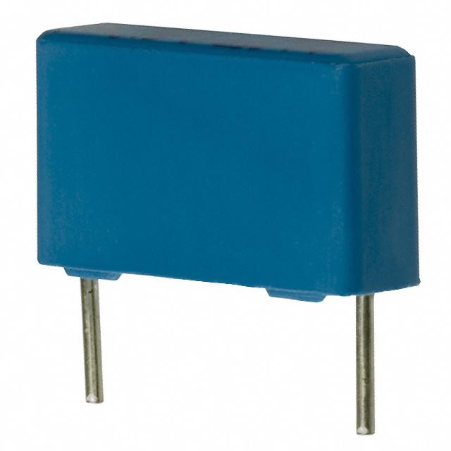
EMI Suppression Capacitors (MKP)
Series/Type:
B81123
Date:
April 2015
© EPCOS AG 2015. Reproduction, publication and dissemination of this publication, enclosures hereto and the
information contained therein without EPCOS' prior express consent is prohibited.
EPCOS AG is a TDK Group Company.
�EMI suppression capacitors (MKP)
B81123
Y1 / 500 V AC
Typical applications
Y1 class for interference suppression
"Line to ground" applications
Double insulation
Dimensional drawing
Climatic
Max. operating temperature: 110 °C
Climatic category (IEC 60068-1): 40/110/56
Construction
Dielectric: polypropylene (MKP)
Internal series connection
Plastic case (UL 94 V-0)
Epoxy resin sealing (UL 94 V-0)
Features
Self-healing properties
RoHS-compatible
Terminals
Parallel wire leads, lead-free tinned
Standard lead lengths: 6 �1 mm
Special lead lengths available on request
Dimensions in mm
Lead spacing
±0.4
15, 22.5
0.8
Marking example
(position of marks may vary):
Marking
Manufacturer's logo, lot number,
date code, rated capacitance (coded),
cap. tolerance (code letter),
rated AC voltage,
series number, sub-class (Y1),
dielectric code (MKP), climatic category,
passive flammability category, approvals.
Delivery mode
Bulk (untaped)
Taped (Ammo pack or reel)
For taping details, refer to chapter
"Taping and packing".
Please read Cautions and warnings and
Important notes at the end of this document.
Lead diameter d1
Page 2 of 19
�B81123
Y1 / 500 V AC
Approvals
Approval marks
Notes:
Standards
EN 60384-14, IEC 60384-14
Certificate
138584
UL1414
UL 60384-14, CSA E60384-14
E97863
E97863 (approved by UL)
Effective January 2014, only for EMI supression capacitors:
– UL 60384-14 certification replaces both UL 1414 and UL 1283 standards.
– CSA C22.2 No. 1 and CSA C22.s No. 8 are replaced by CSA E60384-14.
– References like 1414, 1283 are removed from the capacitor marking
Capacitors under UL1414, UL1283 produced during or before 2013, are
accepted under UL scope.
Capacitors under CSA C22.2 No.1 / No. 8 produced during or before 2013,
are accepted under cUL scope.
Please read Cautions and warnings and
Important notes at the end of this document.
Page 3 of 19
�B81123
Y1 / 500 V AC
Overview of available types
Lead spacing 15 mm
22.5 mm
CR (µF)
0.0010
0.0015
0.0022
0.0033
0.0047
0.0056
0.0068
0.010
Ordering codes and packing units
Lead spacing
CR
mm
15
µF
0.0010
0.0015
0.0022
0.0033
0.0047
0.0056
0.0068
0.010
22.5
Max. dimensions
w×h×l
mm
5.0 × 10.5 × 18.0
6.0 × 11.0 × 18.0
7.0 × 12.5 × 18.0
8.5 × 14.5 × 18.0
9.0 × 17.5 × 18.0
7.0 × 16.0 × 26.5
8.5 × 16.5 × 26.5
10.5 × 18.5 × 26.5
Ordering code
(composition see
below)
B81123C1102M***
B81123C1152M***
B81123C1222M***
B81123C1332M***
B81123C1472M***
B81123C1562M***
B81123C1682M***
B81123C1103M***
Ammo
pack
pcs./MOQ
4680
3840
3320
2720
2560
2320
1920
1560
Reel
pcs./
MOQ
5200
4400
3600
2800
2800
2400
2000
1600
Untaped
pcs./
MOQ
4000
4000
4000
2000
2000
2520
2040
2160
MOQ = Minimum Order Quantity, consisting of 4 packing units.
Composition of ordering code
+ = Capacitance tolerance code:
M = ±20%
Please read Cautions and warnings and
Important notes at the end of this document.
*** = Packaging code:
289 = Straight terminals, Ammo pack
189 = Straight terminals, Reel
003 = Straight terminals, untaped (lead length
3.2 ±0.3 mm)
000 = Straight terminals, untaped (lead length
6 - 1 mm)
Page 4 of 19
�B81123
Y1 / 500 V AC
Technical data
Reference standard: IEC / UL 60384-14. All data given at T = 20 °C unless otherwise specified.
Max. operating temperature Top,max
+110 °C
Dissipation factor tan δ (in 10-3)
at 20 °C (upper limit values)
Insulation resistance Rins
or time constant τ = CR � Rins
at 20 °C, rel. humidity ≤ 65%
(minimum as-delivered values)
at
1 kHz
100 kHz
30 000 MΩ
1.0
5.0
DC test voltage
4800 V, 2 s
The repetition of this DC voltage test may damage the capacitor. Special care must be taken in
case of use several capacitors in a parallel configuration.
Passive flammability category
B
Maximum continuous AC voltage VAC 750 V (50/60 Hz)
Rated AC voltage (UL60384)
500 V (50/60 Hz)
Maximum continuous DC voltage VDC 3000 V
Top ≤ 110 °C Vop = VAC
Top ≤ 110 °C Vop = 1.25 � VAC
temperature
Damp heat test
Limit values after damp heat test
Please read Cautions and warnings and
Important notes at the end of this document.
(continuously)
(1000 h)
56 days / 40 °C / 93% relative humidity
Capacitance change �∆C/C�
≤ 5%
Dissipation factor change ∆ tan δ ≤ 0.5 � 10-3 (at 1 kHz)
Insulation resistance Rins
≤ 1.0 � 10-3 (at 100 kHz)
or time constant τ = CR � Rins
≥ 50% of minimum
as-delivered values
Page 5 of 19
�B81123
Y1 / 500 V AC
Pulse handling capability
"dV/dt" represents the maximum permissible voltage change per unit of time for non-sinusoidal
voltages, expressed in V/µs.
"k0" represents the maximum permissible pulse characteristic of the waveform applied to the
capacitor, expressed in V2/µs.
Note:
The values of dV/dt and k0 provided below must not be exceeded in order to avoid damaging the
capacitor.
dV/dt and k0 values
Lead spacing
dV/dt in V/µs
k0 in V2/µs
15 mm
22.5 mm
1 000
700 000
3 000
2 100 000
Impedance Z versus frequency f
(typical values)
Please read Cautions and warnings and
Important notes at the end of this document.
Page 6 of 19
�B81123
Y1 / 500 V AC
Testing and Standards
Test
Reference
Electrical
Parameters
IEC 60384-14
Robustness of
terminations
Resistance to
soldering heat
Conditions of test
Voltage Proof:
Between terminals: 4000 V AC,
1 min
Terminals and enclosure: 4000 V
AC, 1 min
Insulation resistance, RINS
Capacitance, C
Dissipation factor, tan δ
IEC 60068-2-21 Tensile strength (test Ua1)
Tensile
Wire diameter
force
0.5 < d1 ≤ 0.8 mm
10 N
0.8 < d1 ≤ 1.25 mm 20 N
IEC 60068-2-20, Solder bath temperature at
test Tb,
260 ± 5 °C, immersion for
method 1A
10 seconds
Performance
requirements
Within specified limits
Capacitance and tan δ
within specified limits
∆C/C0 ≤ 5%
tan δ within specified
limits
No visible damage
I∆C/C0 I ≤ 5%
tan δ within specified
limits
Rapid change of IEC 60384-14
temperature
TA = lower category temperature
TB = upper category temperature
Five cycles, duration t = 30 min.
Vibration
IEC 60384-14
Bump
IEC 60384-14
Climatic
sequence
IEC 60384-14
Test FC: vibration sinusoidal
No visible damage
Displacement: 0.75 mm
Accleration: 98 m/s2
Frequency: 10 Hz ... 500 Hz
Test duration: 3 orthogonal axes,
2 hours each axe
Test Eb: Total 4000 bumps with No visible damage
I∆C/C0 I ≤ 5%
400 m/s2 mounted on PCB
tan δ within specified
6 ms duration
limits
Dry heat � TB / 16 h.
No visible damage
Damp heat cyclic, 1st cycle
I∆C/C0 I ≤ 5%
+ 55 °C / 24h / 95% ... 100% RH I∆ tan δ I ≤ 0.008,
Cold � TA / 2h
C ≤ 1 µF
Damp heat cyclic, 5 cycles
I∆ tan δ I > 0.005,
+ 55 °C / 24h / 95% ... 100% rh
C > 1 µF
Voltage proof
RINS ≥ 50% of initial limit
Please read Cautions and warnings and
Important notes at the end of this document.
Page 7 of 19
�B81123
Y1 / 500 V AC
Damp Heat
Steady State
IEC 60384-14
Test Ca
40 °C / 93% RH / 56 days
Impulse test
Endurance
IEC 60384-14
3 impulses
TB / 1.7 VR / 1000 hours,
1000 Vrms for 0.1 s every hour
Passive
flammability
IEC 60384-14
Flame applied for a period of time B
depending on capacitor volume
Please read Cautions and warnings and
Important notes at the end of this document.
Page 8 of 19
No visible damage
I∆C/C0 I ≤ 5%
I∆ tan δ I ≤ 0.008,
C ≤ 1 µF
I∆ tan δ I > 0.005,
C > 1 µF
Voltage proof
RINS ≥ 50% of initial limit
No visible damage
I∆C/C0 I ≤ 10%
I∆ tan δ I ≤ 0.008,
C ≤ 1 µF
I∆ tan δ I > 0.005,
C > 1 µF
Voltage proof
RINS ≥ 50% of initial limit
�B81123
Y1 / 500 V AC
Mounting guidelines
1
Soldering
1.1
Solderability of leads
The solderability of terminal leads is tested to IEC 60068-2-20, test Ta, method 1.
Before a solderability test is carried out, terminals are subjected to accelerated ageing (to
IEC 60068-2-2, test Ba: 4 h exposure to dry heat at 155 °C). Since the ageing temperature is far
higher than the upper category temperature of the capacitors, the terminal wires should be cut off
from the capacitor before the ageing procedure to prevent the solderability being impaired by the
products of any capacitor decomposition that might occur.
Solder bath temperature
235 ±5 °C
Soldering time
2.0 ±0.5 s
Immersion depth
2.0 +0/�0.5 mm from capacitor body or seating plane
Evaluation criteria:
Visual inspection
Wetting of wire surface by new solder ≥90%, free-flowing solder
1.2
Resistance to soldering heat
Resistance to soldering heat is tested to IEC 60068-2-20, test Tb, method 1A.
Conditions:
Series
Solder bath temperature Soldering time
MKT boxed (except 2.5 × 6.5 × 7.2 mm) 260 ±5 °C
coated
uncoated (lead spacing > 10 mm)
MFP
MKP (lead spacing > 7.5 mm)
MKT boxed (case 2.5 × 6.5 × 7.2 mm)
MKP (lead spacing ≤ 7.5 mm)
MKT uncoated (lead spacing ≤ 10 mm)
insulated (B32559)
Please read Cautions and warnings and
Important notes at the end of this document.
Page 9 of 19
10 ±1 s
5 ±1 s


 工商网监
湘ICP备2023018690号
工商网监
湘ICP备2023018690号
