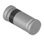
LL101A, LL101B, LL101C
www.vishay.com
Vishay Semiconductors
Small Signal Schottky Diode
FEATURES
• For general purpose applications
• The LL101 series is a metal-on-silicon Schottky
barrier device which is protected by a PN
junction guard ring
• The low forward voltage drop and fast switching
make it ideal for protection of MOS devices,
steering, biasing and coupling diodes for fast switching
and low logic level applications
LINKS TO ADDITIONAL RESOURCES
• Integrated protection ring against static discharge
• Low capacitance
3D 3D
• Low leakage current
3D Models
• This diode is also available in the DO-35 (DO-204AH) case
with type designation SD101A, SD101B, SD101C and in
the SOD-123 case with type designation SD101AW,
SD101BW, SD101CW
MECHANICAL DATA
Case: MiniMELF (SOD-80)
• Material categorization: for definitions of compliance
please see www.vishay.com/doc?99912
Weight: approx. 31 mg
Cathode band color: black
Packaging codes/options:
APPLICATIONS
GS18/10K per 13" reel (8 mm tape), 10K/box
• HF-detector
GS08/2.5K per 7" reel (8 mm tape), 12.5K/box
• Protection circuit
• Diode for low currents wits a low supply voltage
• Small battery charger
• Power supplies
• DC/DC converter for notebooks
PARTS TABLE
PART
TYPE DIFFERENTIATION
CIRCUIT
CONFIGURATION
ORDERING CODE
REMARKS
LL101A
VR = 60 V, VF at IF = 1 mA max. 410 mV
LL101A-GS18 or LL101A-GS08
Single
Tape and reel
LL101B
VR = 50 V, VF at IF = 1 mA max. 400 mV
LL101B-GS18 or LL101B-GS08
Single
Tape and reel
LL101C
VR = 40 V, VF at IF = 1 mA max. 390 mV
LL101C-GS18 or LL101C-GS08
Single
Tape and reel
ABSOLUTE MAXIMUM RATINGS (Tamb = 25 °C, unless otherwise specified)
PARAMETER
TEST CONDITION
Reverse voltage
Power dissipation (infinite heatsink) (1)
Forward continuous current
Maximum single cycle surge 10 μs square wave
PART
SYMBOL
VALUE
UNIT
LL101A
VRRM
60
V
LL101B
VRRM
50
V
LL101C
VRRM
40
V
Ptot
400
mW
IF
30
mA
IFSM
2
A
Note
(1) Valid provided that electrodes are kept at ambient temperature
Rev. 1.6, 16-Nov-2021
Document Number: 85626
1
For technical questions within your region: DiodesAmericas@vishay.com, DiodesAsia@vishay.com, DiodesEurope@vishay.com
THIS DOCUMENT IS SUBJECT TO CHANGE WITHOUT NOTICE. THE PRODUCTS DESCRIBED HEREIN AND THIS DOCUMENT
ARE SUBJECT TO SPECIFIC DISCLAIMERS, SET FORTH AT www.vishay.com/doc?91000
�LL101A, LL101B, LL101C
www.vishay.com
Vishay Semiconductors
THERMAL CHARACTERISTICS (Tamb = 25 °C, unless otherwise specified)
PARAMETER
TEST CONDITION
SYMBOL
VALUE
Tj
125
°C
Tstg
-65 to +150
°C
RthJA
320
K/W
Junction temperature
Storage temperature range
Thermal resistance junction to ambient air
On PC board
50 mm x 50 mm x 1.6 mm
UNIT
ELECTRICAL CHARACTERISTICS (Tamb = 25 °C, unless otherwise specified)
PARAMETER
Reverse Breakdown Voltage
TEST CONDITION
IR = 10 μA
VR = 50 V
Leakage current
Forward voltage drop
Reverse recovery time
SYMBOL
MIN.
V(BR)
60
TYP.
MAX.
UNIT
V
V
LL101B
V(BR)
50
LL101C
V(BR)
40
LL101A
IR
200
nA
V
VR = 40 V
LL101B
IR
200
nA
VR = 30 V
LL101C
IR
200
nA
IF = 1 mA
LL101A
VF
0.410
V
IF = 1 mA
LL101B
VF
0.400
V
IF = 1 mA
LL101C
VF
0.390
V
LL101A
VF
1000
mV
IF = 15 mA
LL101B
VF
950
mV
LL101C
VF
900
mV
LL101A
CD
2.0
pF
LL101B
CD
2.1
pF
LL101C
CD
2.2
pF
trr
1
ns
VR = 0 V, f = 1 MHz
Diode capacitance
PART
LL101A
VR = 0 V, f = 1 MHz
IF = IR = 5 mA, recover to 0.1 IR
TYPICAL CHARACTERISTICS (Tamb = 25 °C, unless otherwise specified)
gll101a_01
Fig. 1 - Typ. IF vs. VF for Primary Conduction through the Schottky
Barrier
gll101a_02
Fig. 2 - Typ. IF of Combination Schottky Barrier and PN Junction
Guard Ring
Rev. 1.6, 16-Nov-2021
Document Number: 85626
2
For technical questions within your region: DiodesAmericas@vishay.com, DiodesAsia@vishay.com, DiodesEurope@vishay.com
THIS DOCUMENT IS SUBJECT TO CHANGE WITHOUT NOTICE. THE PRODUCTS DESCRIBED HEREIN AND THIS DOCUMENT
ARE SUBJECT TO SPECIFIC DISCLAIMERS, SET FORTH AT www.vishay.com/doc?91000
�LL101A, LL101B, LL101C
www.vishay.com
Vishay Semiconductors
gll101a_04
gll101a_03
Fig. 3 - Typical Variation of Reverse Current at Various
Temperatures
Fig. 4 - Typical Capacitance Curve as a Function of Reverse Voltage
PACKAGE DIMENSIONS in millimeters (inches): MiniMELF (SOD-80)
1.6 (0.063)
1.4 (0.055)
Cathode indentification
*
0.47 (0.019) max.
3.7 (0.146)
3.3 (0.130)
* The gap between plug and glass can
be either on cathode or anode side
2.5 (0.098) max.
1.25 (0.49) min.
2 (0.079) min.
Foot print recommendation:
5 (0.197) ref.
Document no.:6.560-5005.01-4
Rev. 8 - Date: 07.June.2006
96 12070
Rev. 1.6, 16-Nov-2021
Document Number: 85626
3
For technical questions within your region: DiodesAmericas@vishay.com, DiodesAsia@vishay.com, DiodesEurope@vishay.com
THIS DOCUMENT IS SUBJECT TO CHANGE WITHOUT NOTICE. THE PRODUCTS DESCRIBED HEREIN AND THIS DOCUMENT
ARE SUBJECT TO SPECIFIC DISCLAIMERS, SET FORTH AT www.vishay.com/doc?91000
�
很抱歉,暂时无法提供与“LL101B-GS18”相匹配的价格&库存,您可以联系我们找货
免费人工找货- 国内价格 香港价格
- 10000+0.4788810000+0.05775
- 30000+0.4699030000+0.05667
- 50000+0.3890950000+0.04692
