NTCC200E4, NTCC300E4
www.vishay.com
Vishay BCcomponents
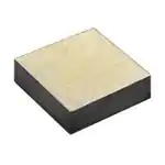
Leadless NTC Thermistor Die Suitable for Wire Bonding
FEATURES
• Flat chip contacted top and bottom
(gold: NTCC300E4 series or silver: NTCC200E4
series)
• Green thermistor - does not use RoHS
exemptions
• Wide temperature range from -55 °C to +175 °C
• Highly resistant to thermal shocks
• Ideal for wire bonding (aluminum or gold
depending on metalization type)
• Resistance to leaching
• Delivered on blister tape
• AEC-Q200 qualified
• Material categorization: for definitions of compliance
please see www.vishay.com/doc?99912
QUICK REFERENCE DATA
PARAMETER
VALUE
UNIT
4.7K to 20K
Ω
± 1; ± 2; ± 3; ± 5
%
APPLICATIONS
3435 to 3865
K
±1
%
Operating temperature range
-55 to +175
°C
Response time (63.2 %)
25 °C to 85 °C still air (for info)
3
s
• High temperature sensing, control and compensation.
E.g. IGBT modules (inverters in EV and HEV vehicles)
• IC and semiconductor protecting
• DC/AC power inverters and HIC overheat protecting
Dissipation factor δ in still air
(for info, non-mounted die)
3
mW
Maximum power dissipation
50
mW
Weight
3
mg
Resistance value at 25 °C
Tolerance on R25-value
B25/85-value
Tolerance on B25/85-value
DESIGN-IN SUPPORT
For complete curve computation, please visit:
www.vishay.com/thermistors/ntc-curve-list/
MARKING
The thermistors have no marking and have electrode
termination design without orientation.
MOUNTING
The thermistors are primarily intended for wire bonding. The
parameters of the assembly process should be chosen in
accordance with the lead-wire material.
The mounting process should be in compliance with the
following guidelines and recommendations:
Die bonding:
• Gold electrode: silver epoxy gluing
• Silver electrode: (vacuum) reflow soldering - silver epoxy
gluing - nano silver sintering
Soldering process under reducing atmosphere (e.g. forming
or formic gases) and ultrasonic cleaning processes can be
applied under the condition that NTC die is not damaged.
Consult Vishay for further assistance.
Wire bonding:
• The gold electrode has been tested for gold wire bonding
with a wire diameter of max. 32 μm
• The silver electrode has been tested for aluminum wire
bonding with a wire diameter of max. 300 μm
Encapsulation:
• In order to preserve the characteristics of the bonded die
at long term an encapsulation is mandatory
• The encapsulation is defined by the user. Silicon and
epoxy encapsulations have been tested. For
recommendations on compatible encapsulants contact
Vishay
ELECTRICAL DATA AND ORDERING INFORMATION
R25
(Ω)
R25-TOL.
(± %)
B25/85
(K)
B25/85-TOL.
(± %)
DESCRIPTION
SAP MATERIAL AND
ORDERING NUMBER (1)
4700
1, 2, 3, 5
3435
1
Bare die with top / bottom silver terminations
NTCC200E4472*T
12 000
1, 2, 3, 5
3740
1
Bare die with top / bottom silver terminations
NTCC200E4123*T
20 000
1, 2, 3, 5
3865
1
Bare die with top / bottom silver terminations
NTCC200E4203*T
4700
1, 2, 3, 5
3435
1
Bare die with top / bottom gold terminations
NTCC300E4472*T
12 000
1, 2, 3, 5
3740
1
Bare die with top / bottom gold terminations
NTCC300E4123*T
20 000
1, 2, 3, 5
3865
1
Bare die with top / bottom gold terminations
NTCC300E4203*T
Note
(1) In order to define R -tolerance, replace * in SAP part number by F (± 1 %), G (± 2 %), H (± 3 %), or J (± 5 %)
25
Revision: 09-Dec-2020
Document Number: 29153
1
For technical questions, contact: nlr@vishay.com
THIS DOCUMENT IS SUBJECT TO CHANGE WITHOUT NOTICE. THE PRODUCTS DESCRIBED HEREIN AND THIS DOCUMENT
ARE SUBJECT TO SPECIFIC DISCLAIMERS, SET FORTH AT www.vishay.com/doc?91000
�NTCC200E4, NTCC300E4
www.vishay.com
Vishay BCcomponents
DIMENSIONS in millimeters
W
T
Wire bondable surface
PARAMETER
VALUE
W
2 ± 0.1
T
0.7 max.
Note
• Non-dimensioned details do not affect the performance of the thermistors
PACKAGING
The components are delivered on 8 mm embossed blister tape (0.3 mm conductive PS) conforming to EIA-481 and IEC 60286-3,
with 2000 parts per reel.
K0
P0
D0
P2
T
F
B0
T2
Revision: 09-Dec-2020
E1
W
A0
PARAMETER
VALUE
A0
2.2 ± 0.1
B0
2.2 ± 0.1
K0
1.0 ± 0.1
W
8 ± 0.3
F
3.5 ± 0.05
E1
1.75 ± 0.1
P0
4.0 ± 0.1
P2
2.0 ± 0.05
D0
1.5 ± 0.1
T
0.35 max.
T2
0.50 max.
Document Number: 29153
2
For technical questions, contact: nlr@vishay.com
THIS DOCUMENT IS SUBJECT TO CHANGE WITHOUT NOTICE. THE PRODUCTS DESCRIBED HEREIN AND THIS DOCUMENT
ARE SUBJECT TO SPECIFIC DISCLAIMERS, SET FORTH AT www.vishay.com/doc?91000
�Legal Disclaimer Notice
www.vishay.com
Vishay
Disclaimer
ALL PRODUCT, PRODUCT SPECIFICATIONS AND DATA ARE SUBJECT TO CHANGE WITHOUT NOTICE TO IMPROVE
RELIABILITY, FUNCTION OR DESIGN OR OTHERWISE.
Vishay Intertechnology, Inc., its affiliates, agents, and employees, and all persons acting on its or their behalf (collectively,
“Vishay”), disclaim any and all liability for any errors, inaccuracies or incompleteness contained in any datasheet or in any other
disclosure relating to any product.
Vishay makes no warranty, representation or guarantee regarding the suitability of the products for any particular purpose or
the continuing production of any product. To the maximum extent permitted by applicable law, Vishay disclaims (i) any and all
liability arising out of the application or use of any product, (ii) any and all liability, including without limitation special,
consequential or incidental damages, and (iii) any and all implied warranties, including warranties of fitness for particular
purpose, non-infringement and merchantability.
Statements regarding the suitability of products for certain types of applications are based on Vishay's knowledge of typical
requirements that are often placed on Vishay products in generic applications. Such statements are not binding statements
about the suitability of products for a particular application. It is the customer's responsibility to validate that a particular product
with the properties described in the product specification is suitable for use in a particular application. Parameters provided in
datasheets and / or specifications may vary in different applications and performance may vary over time. All operating
parameters, including typical parameters, must be validated for each customer application by the customer's technical experts.
Product specifications do not expand or otherwise modify Vishay's terms and conditions of purchase, including but not limited
to the warranty expressed therein.
Hyperlinks included in this datasheet may direct users to third-party websites. These links are provided as a convenience and
for informational purposes only. Inclusion of these hyperlinks does not constitute an endorsement or an approval by Vishay of
any of the products, services or opinions of the corporation, organization or individual associated with the third-party website.
Vishay disclaims any and all liability and bears no responsibility for the accuracy, legality or content of the third-party website
or for that of subsequent links.
Except as expressly indicated in writing, Vishay products are not designed for use in medical, life-saving, or life-sustaining
applications or for any other application in which the failure of the Vishay product could result in personal injury or death.
Customers using or selling Vishay products not expressly indicated for use in such applications do so at their own risk. Please
contact authorized Vishay personnel to obtain written terms and conditions regarding products designed for such applications.
No license, express or implied, by estoppel or otherwise, to any intellectual property rights is granted by this document or by
any conduct of Vishay. Product names and markings noted herein may be trademarks of their respective owners.
© 2022 VISHAY INTERTECHNOLOGY, INC. ALL RIGHTS RESERVED
Revision: 01-Jan-2022
1
Document Number: 91000
�


 工商网监
湘ICP备2023018690号
工商网监
湘ICP备2023018690号
