50RIA Series
Vishay High Power Products
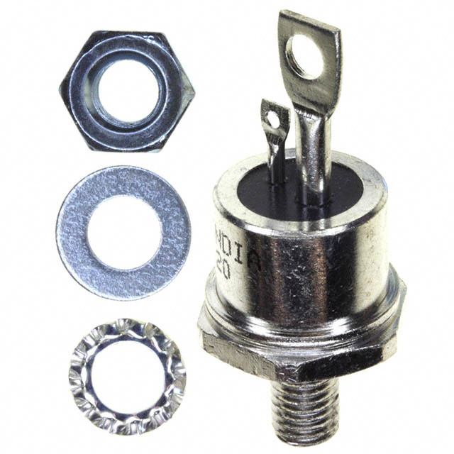
Medium Power Thyristors (Stud Version), 50 A
FEATURES
• High current rating • Excellent dynamic characteristics • dV/dt = 1000 V/µs option • Superior surge capabilities • Standard package • Metric threads version available
TO-208AC (TO-65)
RoHS
COMPLIANT
• Types up to 1200 V VDRM/VRRM • RoHS compliant
TYPICAL APPLICATIONS
• Phase control applications in converters
PRODUCT SUMMARY
IT(AV) 50 A
• Lighting circuits • Battery charges • Regulated power supplies and temperature and speed control circuit • Can be supplied to meet stringent military, aerospace and other high reliability requirements
MAJOR RATINGS AND CHARACTERISTICS
PARAMETER IT(AV) IT(RMS) 50 Hz ITSM 60 Hz 50 Hz 60 Hz VDRM/VRRM tq TJ Typical TEST CONDITIONS VALUES 50 TC 94 80 1430 A 1490 10.18 9.30 100 to 1200 110 - 40 to 125 V µs °C kA2s UNITS A °C A
I2 t
Document Number: 93711 Revision: 19-Sep-08
For technical questions, contact: ind-modules@vishay.com
www.vishay.com 1
�50RIA Series
Vishay High Power Products Medium Power Thyristors
(Stud Version), 50 A
ELECTRICAL SPECIFICATIONS VOLTAGE RATINGS
TYPE NUMBER VOLTAGE CODE 10 20 40 50RIA 60 80 100 120 VDRM/VRRM, MAXIMUM REPETITIVE PEAK AND OFF-STATE VOLTAGE (1) V 100 200 400 600 800 1000 1200 VRSM, MAXIMUM NON-REPETITIVE PEAK VOLTAGE (2) V 150 300 500 700 900 1100 1300 15 IDRM/IRRM MAXIMUM AT TJ = TJ MAXIMUM mA
Notes (1) Units may be broken over non-repetitively in the off-state direction without damage, if dI/dt does not exceed 20 A/µs (2) For voltage pulses with t ≤ 5 ms p
ABSOLUTE MAXIMUM RATINGS
PARAMETER Maximum average on-state current at case temperature Maximum RMS on-state current SYMBOL IT(AV) IT(RMS) t = 10 ms Maximum peak, one-cycle non-repetitive surge current ITSM t = 8.3 ms t = 10 ms t = 8.3 ms t = 10 ms Maximum I2t for fusing I2 t t = 8.3 ms t = 10 ms t = 8.3 ms Maximum I2√t for fusing Low level value of threshold voltage High level value of threshold voltage Low level value of on-state slope resistance High level value of on-state slope resistance Maximum on-state voltage Maximum holding current Latching current I 2 √t VT(TO)1 VT(TO)2 rt1 rt2 VTM IH IL No voltage reapplied 100 % VRRM reapplied No voltage reapplied 100 % VRRM reapplied TEST CONDITIONS 180° sinusoidal conduction VALUES 50 94 80 1430 1490 1200 Sinusoidal half wave, initial TJ = TJ maximum 1255 10.18 9.30 7.20 6.56 101.8 0.94 1.08 4.08 mΩ (π x IT(AV) < I < 20 x π x IT(AV)), TJ = TJ maximum Ipk = 157 A, TJ = 25 °C TJ = 25 °C, anode supply 22 V, resistive load, initial IT = 2 A Anode supply 6 V, resistive load 3.34 1.60 200 400 V mA kA2√s V kA2s A UNITS A °C A
t = 0.1 to 10 ms, no voltage reapplied, TJ = TJ maximum (16.7 % x π x IT(AV) < I < π x IT(AV)), TJ = TJ maximum (π x IT(AV) < I < 20 x π x IT(AV)), TJ = TJ maximum (16.7 % x π x IT(AV) < I < π x IT(AV)), TJ = TJ maximum
www.vishay.com 2
For technical questions, contact: ind-modules@vishay.com
Document Number: 93711 Revision: 19-Sep-08
�50RIA Series
Medium Power Thyristors Vishay High Power Products (Stud Version), 50 A
SWITCHING
PARAMETER Maximum rate of rise of turned-on current Typical delay time Typical turn-off time VDRM ≤ 600 V VDRM ≤ 1600 V dI/dt SYMBOL TEST CONDITIONS TC = 125 °C, VDM = Rated VDRM, Gate pulse = 20 V, 15 Ω, tp = 6 µs, tr = 0.1 µs maximum ITM = (2 x rated dI/dt) A TC = 25 °C, VDM = Rated VDRM, ITM = 10 A dc resistive circuit Gate pulse = 10 V, 15 Ω source, tp = 20 µs TC = 125 °C, ITM = 50 A, reapplied dV/dt = 20 V/µs dIr/dt = - 10 A/µs, VR = 50 V VALUES 200 A/µs 100 0.9 µs 110 UNITS
td tq
BLOCKING
PARAMETER Maximum critical rate of rise of off-state voltage SYMBOL dV/dt TEST CONDITIONS TJ = TJ maximum linear to 100 % rated VDRM TJ = TJ maximum linear to 67 % rated VDRM VALUES 200 500 (1) V/µs UNITS
Note (1) Available with dV/dt = 1000 V/µs, to complete code add S90 i.e. 50RIA120S90
TRIGGERING
PARAMETER Maximum peak gate power Maximum average gate power Maximum peak positive gate current Maximum peak positive gate voltage Maximum peak negative gate voltage SYMBOL PGM PG(AV) IGM +VGM -VGM TJ = - 40 °C DC gate current required to trigger IGT TJ = 25 °C TJ = 125 °C DC gate voltage required to trigger DC gate current not to trigger VGT IGD VGD TJ = - 40 °C TJ = 25 °C TJ = TJ maximum, VDRM = Rated voltage TJ = TJ maximum Maximum gate current/voltage not to trigger is the maximum value which will not trigger any unit with rated VDRM anode to cathode applied Maximum required gate trigger current/voltage are the lowest value which will trigger all units 6 V anode to cathode applied TEST CONDITIONS TJ = TJ maximum, tp ≤ 5 ms VALUES 10 W 2.5 2.5 20 V 10 250 100 50 3.5 V 2.5 5.0 mA mA A UNITS
DC gate voltage not to trigger
0.2
V
Document Number: 93711 Revision: 19-Sep-08
For technical questions, contact: ind-modules@vishay.com
www.vishay.com 3
�50RIA Series
Vishay High Power Products Medium Power Thyristors
(Stud Version), 50 A
THERMAL AND MECHANICAL SPECIFICATIONS
PARAMETER Maximum operating junction and storage temperature range Maximum thermal resistance, junction to case Maximum thermal resistance, case to heatsink SYMBOL TJ, TStg RthJC RthCS DC operation Mounting surface, smooth, flat and greased Non-lubricated threads Allowable mounting torque Lubricated threads Approximate weight Case style See dimensions - link at the end of datasheet TEST CONDITIONS VALUES - 40 to 125 0.35 K/W 0.25 3.4 + 0 - 10 % (30) 2.3 + 0 - 10 % (20) 28 1.0 UNITS °C
N·m (lbf · in) g oz.
TO-208AC (TO-65)
ΔRthJC CONDUCTION
CONDUCTION ANGLE 180° 120° 90° 60° 30° SINUSOIDAL CONDUCTION 0.078 0.094 0.120 0.176 0.294 RECTANGULAR CONDUCTION 0.057 0.098 0.130 0.183 0.296 TJ = TJ maximum K/W TEST CONDITIONS UNITS
Note • The table above shows the increment of thermal resistance RthJC when devices operate at different conduction angles than DC
Maximum Allowable Case Temperature (°C)
50RIA Series RthJC (DC) = 0.35 K/W
Maximum Allowable Case Temperature (°C)
130
130 50RIA Series RthJC (DC) = 0.35 K/W 120
120
Conduction Angle
110
Conduction Period
110 30° 100 60° 90° 120° 180° 90 0 10 20 30 40 50 60 Average On-state Current (A)
100
90 60° 30° 80 0 10 20 30
90° 120° 180° 40 50 60 DC 70 80
Average On-state Current (A)
Fig. 1 - Current Ratings Characteristics
Fig. 2 - Current Ratings Characteristics
www.vishay.com 4
For technical questions, contact: ind-modules@vishay.com
Document Number: 93711 Revision: 19-Sep-08
�50RIA Series
Medium Power Thyristors Vishay High Power Products (Stud Version), 50 A
Maximum Average On-state Power Loss (W) 80 70 60 50 40 30
Conduction Angle
Peak Half Sine Wave On-state Current (A)
180° 120° 90° 60° 30° RMS Limit
1300 1200 1100 1000 900 800 700 600 1
At Any Rated Load Condition And With Rated V RRM Applied Following Surge. Initial TJ = 125°C
@ 60 Hz 0.0083 s @ 50 Hz 0.0100 s
20 10 0 0 10 20
50RIA Series T = 125°C J
50RIA Series
30
40
50
10
100
Average On-state Current (A)
Number Of Equal Amplitude Half Cycle Current Pulses (N)
Fig. 3 - On-State Power Loss Characteristics
Fig. 5 - Maximum Non-Repetitive Surge Current
Maximum Average On-state Power Loss (W)
100 90 80 70 60 50 RMS Limit 40 30 20 10 0 0 10 20 30 40 50 60 70 80 Average On-state Current (A)
Conduction Period
1500 Peak Half Sine Wave On-state Current (A)
DC 180° 120° 90° 60° 30°
1400 1300 1200 1100 1000 900 800 700 600 500 0.01
Maximum Non Repetitive Surge Current Versus Pulse Train Duration. Control Of Conduction May Not Be Maintained. Initial TJ = 125°C No Voltage Reapplied Rated V RRM Reapplied
50RIA Series T = 125°C J
50RIA Series
0.1 Pulse Train Duration (s)
1
Fig. 4 - On-State Power Loss Characteristics
Fig. 6 - Maximum Non-Repetitive Surge Current
1000 Instantaneous On-state Current (A)
100
T = 25°C J 10 T = 125°C J
50RIA Series 1 0.5 1 1.5 2 2.5 3 3.5 4 4.5
Instantaneous On-state Voltage (V)
Fig. 7 - Forward Voltage Drop Characteristics
Document Number: 93711 Revision: 19-Sep-08
For technical questions, contact: ind-modules@vishay.com
www.vishay.com 5
�50RIA Series
Vishay High Power Products Medium Power Thyristors
(Stud Version), 50 A
Transient Thermal Impedance ZthJ-hs (K/W) 1 Steady State Value RthJ-hs = 0.35 K/W
0.1
50RIA Series
0.01 0.001
0.01
0.1 Square Wave Pulse Duration (s)
1
10
Fig. 8 - Thermal Impedance ZthJC Characteristics
100 Rectangular gate pulse a) Recommended load line for rated di/dt : 20V, 30 ohms; tr