VO2223
Vishay Semiconductors
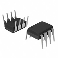
Power Phototriac
FEATURES
• • • • • • • • Maximum trigger current (IFT): 10 mA Isolation test voltage 5300 VRMS Peak off-state voltage 600 V Load current 0.9 ARMS dV/dt of 210 V/µs DIP-8 package Pure tin leads Compliant to RoHS directive 2002/95/EC
Pin 1 2 3 4 5 6 8
21081-1
Function LED cathode LED anode LED cathode LED cathode Triac gate Triac T1 Triac T2
1 2 3 4
V DE
8
6 5
APPLICATIONS
• Home appliances (air conditioners, microwave ovens, washing machines, personal hygiene systems, refrigerators, fan heaters, inductive heating cooker, water heaters, etc.) • Industrial equipments
DESCRIPTION
The VO2223 is an optically couple phototriac driving a power triac in a DIP-8 package. It provides a 5300 V of input to output isolation.
AGENCY APPROVALS
• UL - E52744 system code H • cUL - E52744 system code H • VDE - DIN EN 60747-5-5 (VDE 0884)
ORDER INFORMATION
PART VO2223 VO2223-X001 Note • For additional information on the possible lead bend and VDE options refer to option information. REMARKS Tubes, DIP-8 Tubes, DIP-8
ABSOLUTE MAXIMUM RATINGS
PARAMETER INPUT LED continuous forward current LED reverse voltage OUTPUT Repetitive peak off-state voltage On-state RMS current Peak non-repetitive surge current (60 Hz, 1 cycle) COUPLER Total power dissipation (3) Ambient temperature range Storage temperature range Soldering temperature (2) Isolation test voltage
(1)
(Tamb = 25 °C, unless otherwise specified)
SYMBOL IF VR VALUE 50 6 UNIT mA V
TEST CONDITION
Sine wave, 50 Hz to 60 Hz, gate open
VDRM IT(RMS) ITSM
600 0.9 9
V A A
Pdiss Tamb Tstg t ≤ 10 s max. for 1 s Tsld VISO
1.2 - 40 to + 85 - 40 to + 125 260 5300
W °C °C °C VRMS
Notes (1) Stresses in excess of the absolute maximum ratings can cause permanent damage to the device. Functional operation of the device is not implied at these or any other conditions in excess of those given in the operational sections of this document. Exposure to absolute maximum ratings for extended periods of the time can adversely affect reliability. (2) Refer to wave profile for soldering conditions for through hole devices. (3) Total power dissipation value is based on 2S2P PCB. Document Number: 81166 Rev. 1.1, 19-Mar-10 For technical questions, contact: optocoupleranswers@vishay.com www.vishay.com 1
�VO2223
Vishay Semiconductors
Power Phototriac
ABSOLUTE MAXIMUM RATING CURVES
80 1.0 0.9
LED Power (mW)
Load Current (A)
0 20 40 60 80 100 120
60
0.8 0.7 0.6 0.5 0.4 0.3 0.2 0.1
40
20
0 - 40 - 20
21296
0 - 40
21906
10
60
110
TA - Ambient Temperature (°C)
Fig. 1 - Power Dissipation vs. Temperature
Ambient Temperature (°C)
Fig. 2 - Allowable Load Current vs. Ambient Temperature Note • The allowable load current was calculated out under a given operating conditions and only for reference: LED power: QE = 0.015 W, θBA (4-layer) = 30 °C/W
ELECTRICAL CHARACTERISTICS
PARAMETER INPUT LED trigger current LED reverse current LED forward voltage OUTPUT Peak on-state voltage Peak off-state current Holding current Critical rate of rise of off-state voltage
(1)
(Tamb = 25 °C, unless otherwise specified)
SYMBOL IFT IR VF VTM IDRM IH dV/dt 210 0.9 MIN. TYP. MAX. 10 10 1.3 2.5 100 25 UNIT mA µA V V µA mA V/µs
TEST CONDITION VT = 6 V VR = 5 V IF = 10 mA IF = 10 mA, ITM = max. IF = 10 mA, VDRM = 600 V RL = 100 Ω VIN = 400 VRMS (fig. 3)
Critical rate of rise of commutating VIN = 240 VRMS, dV/dt (c) 0.7 V/µs voltage IT = 1 ARMS (fig. 3) Note (1) Minimum and maximum values are testing requirements. Typical values are characteristics of the device and are the result of engineering evaluations. Typical values are for information only and are not part of the testing requirements.
RIN + VCC 120 Ω AC RL VIN
RL RTEST VIN Mon CTEST
5 V, VCC
0V dV/dt (c)
21575
dV/dt
Fig. 3 - dV/dt Test Circuit
www.vishay.com 2
For technical questions, contact: optocoupleranswers@vishay.com
Document Number: 81166 Rev. 1.1, 19-Mar-10
�VO2223
Power Phototriac
Vishay Semiconductors
SAFETY AND INSULATION RATINGS
PARAMETER Climatic classification Pollution degree Tracking resistance (comparative tracking index) Highest allowable overvoltage Maximum working insulation voltage Insulation resistance at 25 °C Insulation resistance at TS Insulation resistance at 100 °C Partial discharge test voltage Safety limiting values maximum values allowed in the event of a failure Case temperature Input current Output power
(1)
TEST CONDITION IEC 68 part 1 DIN VDE 0109 Insulation group IIIa Transient overvoltage Recurring peak voltage VIO = 500 V VIO = 500 V VIO = 500 V Method b, Vpd = VIORM x 1.6
SYMBOL
MIN.
TYP. 40/85/21 2
MAX.
UNIT
CTI VIOTM VIORM RIS RIS RIS Vpd TSI ISI PSO
175 8000 890 ≥ 1012 ≥ 10 9 ≥ 1011 1424 165 150 2000 ≥7 Vpeak Vpeak Ω Ω Ω Vpeak °C mA mW mm
Minimum external air gap (clearance distance)
Measured from input terminals to output terminals, shortest distance through air Measured from input terminals to output terminals, shortest distance path along body
Minimum external tracking (creepage distance)
≥7
mm
Note (1) This phototriac coupler is suitable for “safe electrical insulation” only within the safety ratings. Compliance with safety ratings shall be ensured by means of protective circuits.
TYPICAL CHARACTERISTICS (Tamb = 25 °C, unless otherwise specified)
100 55
IF - Forward Current (mA)
VR - Reverse Voltage (V)
110 °C
85 °C 25 °C 10 0 °C 55 °C - 40 °C 1 0.8 1 1.2 1.4 1.6
50
45
40 - 40
21908
- 15
10
35
60
85
110
21907
VF - Forward Voltage (V)
Tamb - Temperature (°C)
Fig. 4 - Forward Current vs. Forward Voltage
Fig. 5 - Reverse Voltage vs. Temperature
Document Number: 81166 Rev. 1.1, 19-Mar-10
For technical questions, contact: optocoupleranswers@vishay.com
www.vishay.com 3
�VO2223
Vishay Semiconductors
Power Phototriac
ITM - Peak On-State Current (A)
1.8 1.2 0.6 0 - 0.6 - 1.2 - 1.8 - 1.8
50
IFT - Trigger Current (mA)
40
30
20
10 - 1.2 - 0.6 0 0.6 1.2 1.8
21912
1
10
100
21909
VTM - Peak On-State Voltage (V)
Turn-on Time (µs)
Fig. 6 - On-State Current vs. On-State Voltage
Fig. 9 - Trigger Input Current vs. Turn-on Time
Off-State Leakage Current (nA)
100 000 110 °C 10 000 1000 100 10 1 - 40 °C 0.1 0 0
21910
2.5
85 °C 55 °C 25 °C 0 °C
Holding Current (mA)
2.0
1.5 1.0
0.5
100
200
300
400
500
600
21913
0 - 40
- 10
20
50
80
110
Supply Voltage (V)
Tamb - Temperature (°C)
Fig. 7 - Off-State Leakage Current vs. Voltage
Fig. 10 - Normalized Holding Current vs. Temperature
1.5 1.3 1.2 1.1 1.0 0.9 0.8 0.7 0.6 0.5 - 40
21911
5.5
Trigger Input Current (mA)
- 10 20 50 80 110
1.4
IFT - Trigger Current (mA)
5.0 4.5
4.0 3.5
3.0 20
21914
40
60
80
100
Tamb - Temperature (°C)
Trigger Pulse Width (µs)
Fig. 8 - Normalized Trigger Input Current vs. Temperature
Fig. 11 - Trigger Current vs. Trigger Pulse Width
www.vishay.com 4
For technical questions, contact: optocoupleranswers@vishay.com
Document Number: 81166 Rev. 1.1, 19-Mar-10
�VO2223
Power Phototriac
Vishay Semiconductors
5
IFT - Trigger Current (mA)
4
3
2
1 0
21915
100
200
300
400
500
600
VLOAD (V)
Fig. 12 - Trigger Current vs. VLOAD
PACKAGE DIMENSIONS in millimeters
Pin one ID 4 6.48 6.81 5 6 8 3 2 1
ISO method A
9.63 9.91 0.76 1.14 4° typ. 3.30 3.81 1.27 0.46 0.56 2.54 typ.
i178006-1
7.62 typ. 0.79
10° 0.51 0.89 3° to 9° 0.2 0.3
2.79 3.30
5.84 6.35
PACKAGE MARKING
VO2223 V YWW H 68
21764-48
Document Number: 81166 Rev. 1.1, 19-Mar-10
For technical questions, contact: optocoupleranswers@vishay.com
www.vishay.com 5
�Legal Disclaimer Notice
Vishay
Disclaimer
All product specifications and data are subject to change without notice. Vishay Intertechnology, Inc., its affiliates, agents, and employees, and all persons acting on its or their behalf (collectively, “Vishay”), disclaim any and all liability for any errors, inaccuracies or incompleteness contained herein or in any other disclosure relating to any product. Vishay disclaims any and all liability arising out of the use or application of any product described herein or of any information provided herein to the maximum extent permitted by law. The product specifications do not expand or otherwise modify Vishay’s terms and conditions of purchase, including but not limited to the warranty expressed therein, which apply to these products. No license, express or implied, by estoppel or otherwise, to any intellectual property rights is granted by this document or by any conduct of Vishay. The products shown herein are not designed for use in medical, life-saving, or life-sustaining applications unless otherwise expressly indicated. Customers using or selling Vishay products not expressly indicated for use in such applications do so entirely at their own risk and agree to fully indemnify Vishay for any damages arising or resulting from such use or sale. Please contact authorized Vishay personnel to obtain written terms and conditions regarding products designed for such applications. Product names and markings noted herein may be trademarks of their respective owners.
Document Number: 91000 Revision: 18-Jul-08
www.vishay.com 1
�


 工商网监
湘ICP备2023018690号
工商网监
湘ICP备2023018690号
