DLP-MAVLCD1
LEAD FREE
LCD / MICROCONTROLLER MODULE
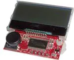
The DLP-MAV-LCD1 combines a 2x16-character backlit LCD display with a TI MSP430
microcontroller to form a MAVRK-supported display module. The MSP430 is preprogrammed with
basic functionality for driving the LCD display via either the MAVRK platform or a simple, 5-pin TTL
serial interface.
FEATURES:
•
•
•
•
•
Simple ASCII Command Set
Requires 3.0-3.3V Supply
LED Backlight
5-Switch Joystick (Left, Right, Up, Down and Select)
Can Be Used Standalone or with the MAVRK Platform
1.0 GENERAL DESCRIPTION
The DLP-MAV-LCD1 provides the MAVRK platform with a means of displaying data that does not
require a connected host PC.
To send data from the host processor on the MAVRK platform via the 2-wire TTL serial interface, the
host firmware sends the data to be displayed using the format described below in Section 3.
When the 5-switch joystick is operated, the DLP-MAV-LCD1 issues switch closure information to the
host processor using the MAVRK platform protocol. This protocol consists of a printable ASCII format
using a synchronization character “^”, and a termination character “~”. (This protocol is further
described in Section 3.)
The DLP-MAV-LCD1 is ready to accept commands immediately upon power up. (Initial baud rate and
serial parameters are outlined in Section 3.)
Rev. 1.0 (February 2012)
1
© DLP Design, Inc.
�2.0 MAVRK QUICK START GUIDE
This guide requires the use of a MAVRK platform (purchased separately).
1. Connect the DLP-MAV-LCD1 module to one of the four LTE positions on the MAVRK platform
via the connector on the bottom side of the DLP-MAV-LCD1 module:
Figure 1: MAVRK Board with DLP-MAV-LCD1 Installed in Position AFE #4
2. Install the firmware as described on the MAVRK wiki pages:
http://processors.wiki.ti.com/index.php/MAVRK_Introduction, specifically the “How do I
get started with MAVRK?” section. Begin by creating a SVN folder at C:\svn.
3. Once installed, locate the project:
C:\svn\mavrk\mavrk_embedded\Modular_EVM_Projects\System_Demo_Projects\MSP43
0F5438-MVK_UART_Passthrough
4. Open the project in Code Composer 5.1 or later.
5. Find the file “MSP430F5438_UART_Passthrough_main.c”, then edit the following lines in the
function main():
//
//
mvk_Configure_UART_Passthrough (MAVRK_UART_RF, MAVRK_UART_TUSB);
mvk_Configure_UART_Passthrough (MAVRK_UART_TUSB, MAVRK_UART_RF);
6. Add the following lines in the function main() under the ones you just commented out above:
mvk_Configure_UART_Passthrough (MAVRK_UART_P1P2, MAVRK_UART_TUSB);
mvk_Configure_UART_Passthrough (MAVRK_UART_TUSB, MAVRK_UART_P1P2);
7. Rebuild the project, and reload the MAVRK platform with your new flash.
Rev. 1.0 (February 2012)
2
© DLP Design, Inc.
�8. Now you can connect the USB cable to the MAVRK debug port and open a terminal interface
(ex: HyperTerminal) to the MAVRK platform using the following settings: Baud: 460800, N,
8, 1.
9. Once connected, actuating the joystick will result in data being displayed that indicates which
joystick button was pressed. The terminal window may also be used to send commands and
data characters to the LCD.
The DLP-MAV-LCD1 module is shipped preprogrammed with firmware for either communicating
directly with the MAVRK platform or for operation in standalone mode via the 5-pin header.
Figure 2: DLP-MAV-LCD1 Module Ready to Start Right Out of the Box
Figure 2 will be displayed for 5 seconds, and then the display will be clear as shown in Figure 3:
Figure 3: Clear (After 5 Seconds)
At this point, the DLP-MAV-LCD1 is ready for use. (Note that the unit will appear non-responsive on
the MAVRK platform until you build and load your new MAVRK platform flash file as described in
Section 2.)
Alternatively, you can communicate directly with the unit in standalone mode. Troubleshooting
information will also be available on the MAVRK wiki pages referenced above.
Rev. 1.0 (February 2012)
3
© DLP Design, Inc.
�3.0 COMMAND AND DATA SET
The command and data set syntax communicates via a two-wire serial TTL interface:
Parameter
Baud Rate
Data
Parity
Stop Bit
Flow Control
Value
460800
8 Bit
None
1
None
Table 1: Sample Data and Commands
Changing the Baud Rate via the Menu:
Figure 4: Splash Screen on Power Up
Changing the baud rate may be accomplished; however, you must press Select (joystick straight
down) to initiate the Baud Rate Menu. (Note that this must be done during the first 5 seconds when
the splash screen shown above is displayed.)
Figure 5: Baud Rate Menu
Once Select has been pressed, the Baud Rate Menu (see Figure 5) will be displayed.
Rev. 1.0 (February 2012)
4
© DLP Design, Inc.
�From this Baud Rate Menu, press the up or down buttons on the toggle to increase or decrease the
baud rate. (Standard baud rates are detailed in Table 3 below.)
Figure 6: Baud Rate 9600
You may now press the Select button once your baud rate is displayed. This saves the selected baud
rate into flash. On subsequent power ups, the following screen will be displayed indicating the saved
baud rate:
Figure 7: Power Up Splash Screen
Changing the Baud Rate via the Terminal Emulator:
To change the baud rate, first set the baud rate of the terminal to 460800 as described above. Then
send the command ^b9600~, at which point the new baud rate will immediately be in effect. (You will
have to change your terminal to 9600 immediately to continue processing any further commands.)
The TTL interface requires the specific formatting described below for all message traffic to and from
the LCD:
Rev. 1.0 (February 2012)
5
© DLP Design, Inc.
�Function
Sending Data
Sending
Commands
Sending a New
Baud Rate
Receiving Keys
Synchronization
Characters
^d
Command or Data
Buffer
Hello World
Termination
Character
~
^dHello World~
^c
01
~
^c01~
^b
9600
~
^b9600~
^k
U
~
^kU~
Example
Table 2: Data and Commands Syntax
Command
1200
2400
4800
9600
14400
19200
38400
57600
115200
230400
Sent Text
^b1200~
^b2400~
^b4800~
^b9600~
^b14400~
^b19200~
^b38400~
^b57600~
^b115200~
^b230400~
460800
^b460800~
921600
^b921600~
Baud Rate
1200
2400
4800
9600
14400
19200
38400
57600
115200
230400
460800
(Default)
921600
Table 3: Standard Baud Rates
Data that exceeds the 16 character lines will be truncated based on the length of the display. Both
the top and bottom LCD lines require separate data commands.
Joystick
Up
Down
Left
Right
Received Text
^kU~
^kD~
^kL~
^kR~
Select
^kS~
Description
Key Up was Pressed
Key Down was Pressed
Key Left was Pressed
Key Right was Pressed
Key Select (Center Down)
was Pressed
Table 4: Key Definitions
Keys will be sent to the connected terminal with de-bounce. If you hold the key down longer than
500mS, it will repeat.
Rev. 1.0 (February 2012)
6
© DLP Design, Inc.
�Command
Sent Text
80
^c80~
C0
^cC0~
F1
F0
^cF1~
^cF0~
Description
Cursor Location to Row 1/Column 1
(see Table 6)
Cursor Location to Row 2/Column 1
(see Table 6)
Turn the LCD Backlight On
Turn the LCD Backlight Off
E1
^cE1~
Turn Echo On
E0
^cE0~
Turn Echo Off (Default)
01
^c01~
Clears the Screen
02
^c02~
08
^c08~
09
^c09~
0A
^c0A~
0B
^c0B~
0C
^c0C~
0D
^c0D~
0E
^c0E~
0F
^c0F~
7x
^c70~
Return Home
Display OFF
Cursor OFF
Cursor Position OFF
Display OFF
Cursor OFF
Cursor Position ON
Display OFF
Cursor ON
Cursor Position OFF
Display OFF
Cursor ON
Cursor Position ON
Display ON
Cursor OFF
Cursor Position OFF
Display ON
Cursor OFF
Cursor Position ON
Display ON
Cursor ON
Cursor Position OFF
Display ON
Cursor ON
Cursor Position ON
Set Contrast Value to x Where x is
0,1,2,3,4,5,6,7,8,9,A,B,C,D,E or F
Table 5: Commands Definition
The table below describes the Cursor Location Commands for each on-screen position based on the
row and column required. Once each command has been issued, the next data command will start
writing text from this location and will automatically increment to the next location based upon the
length of the text string:
Rev. 1.0 (February 2012)
7
© DLP Design, Inc.
�Row
1
1
1
1
1
1
1
1
1
1
1
1
1
1
1
1
2
2
2
2
2
2
2
2
2
2
2
2
2
2
2
2
Column
1
2
3
4
5
6
7
8
9
10
11
12
13
14
15
16
1
2
3
4
5
6
7
8
9
10
11
12
13
14
15
16
Command
80
81
82
83
84
85
86
87
88
89
8A
8B
8C
8D
8E
8F
C0
C1
C2
C3
C4
C5
C6
C7
C8
C9
CA
CB
CC
CD
CE
CF
Example
^c80~
^c81~
^c82~
^c83~
^c84~
^c85~
^c86~
^c87~
^c88~
^c89~
^c8A~
^c8B~
^c8C~
^c8D~
^c8E~
^c8F~
^cC0~
^cC1~
^cC2~
^cC3~
^cC4~
^cC5~
^cC6~
^cC7~
^cC8~
^cC9~
^cCA~
^cCB~
^cCC~
^cCD~
^cCE~
^cCF~
Table 6: Cursor Location Definitions
The table below describes sample strings sent to the DLP-MAV-LCD1 to include clearing the screen
and positioning the cursor prior to writing text:
Rev. 1.0 (February 2012)
8
© DLP Design, Inc.
�Data
Hello
Example
^dHello~
Testing 123
^d Testing 123~
Beyond the
Maximum Text
Length of 16
^dBeyond the
Maximum Text Length
of 16~
Line 1 Here
^c01~^c80~^dLine 1
Here~
Line 2 Here
^c01~^cc0~^dLine 2
Here~
Description
Displays “Hello”
Displays “ Testing
123” (note that the
spaces are valid)
The Data is
Ignored
Clears the Screen,
Goes to Row 1/
Column 1 and
Displays “Line 1
Here”
Clears the Screen,
Goes to Row 2/
Column 1 and
Displays “Line 2
Here”
Table 7: Sample Commands
4.0 STANDALONE MODE
Alternatively, when used in standalone mode, the DLP-MAV-LCD1 board may be powered externally
and communicated with utilizing the 5-pin, TTL serial header described below:
1
5
Figure 8: DLP-MAV-LCD1 Standalone Pins
Pin #
1
2
3
4
5
Description
FROM EXTERNAL HOST (In) – TTL serial from host processor
TO EXTERNAL HOST (Out) – TTL serial to host processor
GROUND
RESET (In) – Pull to ground to reset MSP430 on DLP-MAV-LCD1
3.0 - 3.3V (In) – Power supply for module
Table 8: TTL 5-Pin Header Descriptions
Rev. 1.0 (February 2012)
9
© DLP Design, Inc.
�5.0 MECHANICAL DRAWINGS
Both inches and (millimeters) in parentheses are shown below for each measurement:
1.64 typ
(41.7 typ)
0.963 typ
(24.5 typ)
1.515 typ
(38.5 typ)
2 x 0.157 typ
(4.0 typ)
1.50 typ
(38.1 typ)
Figure 9: DLP-MAV-LCD1 Dimensions
6.0 DISCLAIMER
Neither the whole nor any part of the information contained within or the product described in this
datasheet may be adapted or reproduced in any material or electronic form without the prior written
consent of the copyright holder.
This product and its documentation are supplied on an as-is basis, and no warranty as to their
suitability for any particular purpose is either made or implied. DLP Design will not accept any claim
for damages whatsoever arising as a result of use or failure of this product. Your statutory rights are
not affected.
This product or any variant of it is not intended for use in any medical appliance, device or system in
which the failure of the product might reasonably be expected to result in personal injury.
This document provides preliminary information that may be subject to change without notice.
Rev. 1.0 (February 2012)
10
© DLP Design, Inc.
�7.0 CONTACT INFORMATION
DLP Design, Inc.
1605 Roma Lane
Allen, TX 75013
Phone:
Fax:
Email Sales:
Email Support:
Website URL:
469-964-8027
415-901-4859
sales@dlpdesign.com
support@dlpdesign.com
http://www.dlpdesign.com
Rev. 1.0 (February 2012)
11
© DLP Design, Inc.
�