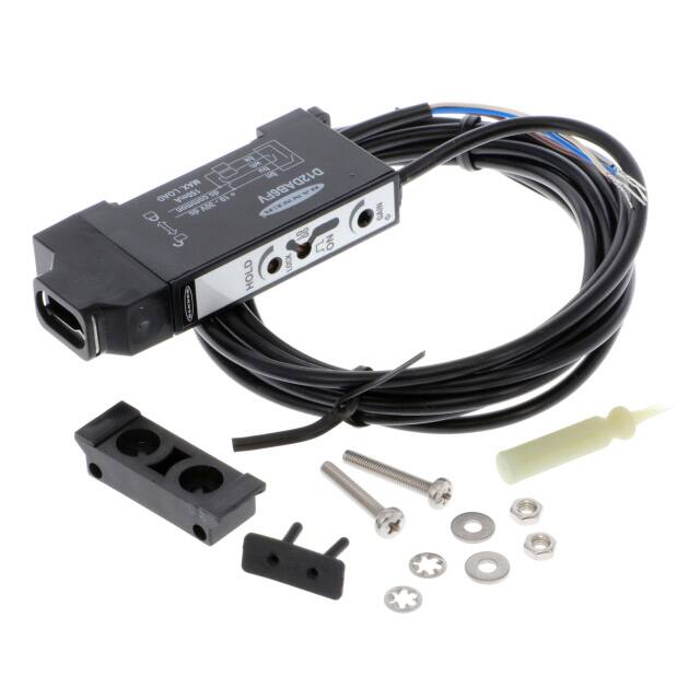
D12DAB6 Series DIN Rail AC-coupled Fiber Optic Sensor
Datasheet
Special-Purpose Glass and Plastic Fiber Optic Sensors for Low-Contrast Applications
•
•
•
•
•
•
•
•
Highly sensitive to very small signal changes; fast response
Automatic gain control circuit continually adjusts emitter output to maintain system gain
Ideal for low contrast applications such as web flaw, thread break, and falling parts detection
Sensors operate from 10 V dc to 30 V dc
One NPN and one PNP output; 150 mA maximum (continuous) load
LED indicators for power on, output conducting , and AGC lock conditions
Selectable light- or dark-operate; no false pulse on power-up
Models available for use with glass fibers or plastic fibers
WARNING: Not To Be Used for Personnel Protection
Never use this device as a sensing device for personnel protection. Doing so could lead to serious injury or death.
This device does not include the self-checking redundant circuitry necessary to allow its use in personnel safety
applications. A sensor failure or malfunction can cause either an energized or de-energized sensor output
condition.
CAUTION: Electrostatic Discharge (ESD)
ESD Sensitive Device. Use proper handling procedures to prevent ESD damage to these devices. The module does
not contain any specific ESD protection beyond the structures contained in its integrated circuits. Proper handling
procedures should include leaving devices in their anti-static packaging until ready for use; wearing anit-static wrist
straps; and assembling units on a grounded, static-dissipative surface.
Models
Glass Fiber Optic Sensors
Model
Output
D12DAB6FV
D12DAB6FV W/30
Connection
Range
2 m (6.5 ft) attached cable
One NPN and
one PNP
D12DAB6FVQ
9 m (30 ft) attached cable
Range varies by sensing mode and
fiber optics used
150 mm (6-in) with pico-style QD
Plastic Fiber Optic Sensors
Model
Output
D12DAB6FP
D12DAB6FP W/30
D12DAB6FPQ
Connection
Range
2 m (6.5 ft) attached cable
One NPN and
one PNP
9 m (30 ft) attached cable
Range varies by sensing mode and
fiber optics used
150 mm (6-in) with pico-style QD
Overview
D12DAB6 Series sensors are compact, ac-coupled sensors designed for use with Banner glass or plastic fiber optics. They are intended
for applications in which the light signal change is so small that sensitivity adjustment of ordinary dc-coupled sensors is difficult or
impossible. D12DAB6 Series sensors can respond to even smaller signal changes than the standard D12 fiber optic sensors, and are less
affected by gradual signal changes due to dirt buildup, etc. Typical applications include thread break detection, web flaw detection, and
detection of small parts falling randomly from vibratory feeders or small presses.
Original Document
38384 Rev. C
11 September 2017
38384
�D12DAB6 Series DIN Rail AC-coupled Fiber Optic Sensor
D12DAB6 Series sensors reliably amplify the small signal changes found in many low contrast sensing applications. An automatic gain
control (AGC) feedback system locks onto the light signal and continually adjusts the light intensity of the emitter so that the system is
always maintained at the desired reference level regardless of the sensing range or the degree of environmental contamination. A
multi-turn control enables setting of the amplifier sensitivity.
Model D12DAB6FV models are for use with Banner glass fiber optic assemblies. The D12DAB6FP plastic fiber models may be used with
either the small diameter (0.508 mm or 0.020-inch) or large diameter (1.016 mm or 0.040-inch) Banner cut-to-length plastic fiber optics.
D12DAB6 Series sensors have a POWER ON indicator, a LOCK indicator that lights when the AGC circuit has locked onto the signal, and
an output indicator that lights whenever the sensor's outputs are energized.
A switch on the sensor's top panel selects either light- or dark-operate. When light-operate is selected, output occurs on a dark-to-light
transition. When dark-operate is selected, output occurs on a light-to-dark transition.
Output pulse width adjust
AGC LOCK indicator
Light/Dark Operate select
Output indicator
Power ON indicator
15-turn sensitivity
(Gain) control
Figure 1. Sensor Features (Top Panel Shown)
Installation
Installing Glass Fibers
1. Gently seat an o-ring onto each sensor end of the fiber.
Sensor end, glass fiber
O-ring (supplied with fiber)
Groove
2. Slide the sensor ends into the fiber ports as far as they will go.
3. Push firmly on the fiber ends to compress the o-ring, and while holding the sensor ends snugly in place, slide the fiber retaining
clip into the slot.
4. Press the retaining clip in until it snaps into the groove.
Installing Plastic Fibers
1. Cut the fiber ends according to the instructions included with the fibers.
2. Slide the fiber gripper up (open).
3. If you are using 0.254 mm or 0.508 mm (0 .010 inch or 0.020 inch) diameter fibers: Insert the adaptor into the ports as far as it
will go.
Fiber adapter
4. For all fiber diameters: Insert the prepared plastic fiber sensor ends gently into the ports as far as they will go.
5. Slide the fiber gripper back down to lock it.
Alignment
1. Attach two individual fiber optic assemblies (or one bifurcated fiber optic assembly) to the D12DAB6 Series sensor using the
instructions packed with the fiber.
2
www.bannerengineering.com - Tel: +1-763-544-3164
P/N 38384 Rev. C
�D12DAB6 Series DIN Rail AC-coupled Fiber Optic Sensor
2. Mount and align the sensing end(s) of the fiber(s) at the sensing location in a position that will optimize the differential
between the light and dark conditions.
Do not connect the load at this time: the LOAD (amber) LED will simulate the action of the load.
3. Connect the brown and blue wires from the sensor to a +10 V dc to 30 V dc source (see wiring diagram).
4. Apply dc power and verify that the POWER ON LED (green) is on.
5. Set the LO/DO switch to DO (dark operate).
6. Present the light condition to the sensor.
7. Make sure that the LOCK LED (red) stays on. If necessary, adjust the fiber ends so that the red LOCK LED stays on reliably.
Note: If the light condition is a quick transition that cannot be simulated as a static condition and the dark
condition is the normal condition, set the LO/DO switch to LO (light operate). Adjust the fiber ends so that,
when the light condition occurs, the amber LOAD indicator LED turns on reliably.
8. Simulate the sensing event to the sensor while observing the amber LOAD LED.
9. If necessary, adjust the GAIN control (clockwise to increase) so that the LOAD LED changes state positively and reliably to all
desired variations of the sensing event.
Note that too much gain may result in unwanted response to conditions such as vibration of the sensing ends, etc.
10. While observing the LOAD LED, adjust the output pulse length using the sensor's 3/4-turn HOLD control.
Minimum on time is 1 millisecond; maximum on time is 70 milliseconds.
11. Connect the load to the sensor and check the system.
Wiring Diagram
Key
1
+
10-30V dc
–
3
2
4
Load
1 = Brown
2 = White
3 = Blue
4 = Black
Load
The sensor operates normally if the supply voltage polarity is reversed; however, the white and black wires must always be wired as
shown.
P/N 38384 Rev. C
www.bannerengineering.com - Tel: +1-763-544-3164
3
�D12DAB6 Series DIN Rail AC-coupled Fiber Optic Sensor
Specifications
D12DAB6FV—Sensing modes and minimum guaranteed ranges (3-foot fibers)
Sensing Beam
Visible red, 680 nm
Supply voltage
+10 V dc to 30 V dc at 60 mA max, exclusive of load
Supply Protection Circuitry
Protected against reverse polarity and transient overvoltages
Output configuration
One NPN (current sinking) and one PNP (current sourcing) open-collector
transistor
Output rating
150 mA maximum each output
No false pulse on power-up. False pulse protection circuit causes a 0.1 second
delay on power-up
Short-circuit protected
Off-state leakage current: < 10 microamps at 30 V dc.
On-state saturation voltage: < 1 V at 10 mA dc; < 1.5 V at 150 mA dc
The total load may not exceed 150 mA
Output pulse: time adjustable, 1 to 70 milliseconds
Response time
50 microseconds on
Repeatability
15 microseconds
Indicators
Three top-mounted LED indicators, one amber, one green, and one red
Green on: dc power on
Amber on: output conducting
Red on: whenever the AGC system is locked onto the signal
Adjustments (three top-panel controls)
Sensitivity control is a 15-turn slotted brass screw, clutched at both ends of
adjustment
Light- or Dark-operate select switch
Output Pulse adjustment is a 3/4-turn potentiometer
Construction
Black ABS housing with acrylic cover
Acetal fiber clamping element
Stainless steel M3 × 0.5 hardware for use with mounting bracket (supplied)
Environmental Rating
NEMA 4, IEC IP66
Cable
2 m (6.5 ft) or 9 m (30 ft) attached PVC-covered cable, or 150 mm (6-in) with
Pico-style 4-pin QD connector
Mode
Glass Fiber and Lens
Guaranteed Range (3-ft fibers)
Opposed
1.588 mm (1/16-in)
fibers, no lenses
75 mm (3 in)
Opposed
1.588 mm (1/16-in)
fibers, L9 lenses
> 150 cm (60 in)1
Opposed
1.588 mm (1/16-in)
fibers, L16F lenses
> 150 cm (60 in)1
Diffuse
1.588 mm (1/16-in)
fibers, no lenses
25 mm (1 in); distance to 90%
reflectance white test card
Opposed
3.175 mm (1/8-in) fibers,
no lenses
20 cm (8 in)
Opposed
3.175 mm (1/8-in) fibers,
L9 lenses
> 150 cm (60 in)1
Opposed
3.175 mm (1/8-in) fibers,
L16F lenses
> 150 cm (60 in)1
Diffuse
3.175 mm (1/8-in) fibers,
no lenses
60 mm (2.5 in); distance to 90%
reflectance white test card
D12DAB6FP—Sensing modes and minimum guaranteed ranges (6-foot fibers)
Mode
Plastic Fiber and Lens
Guaranteed Range (6-ft fibers)
Opposed
0.508 mm (0.020-in)
fibers, no lenses
13 mm (0.5 in)
Diffuse
0.508 mm (0.020-in)
fibers, no lenses
5 mm (0.2 in); distance to 90%
reflectance white test card
Opposed
1.016 mm (0.040-in)
fibers, no lenses
76 mm (3 in)
Opposed
1.016 mm (0.040-in)
fibers, L2 lenses
76 cm (30 in)
Opposed
1.016 mm (0.040-in)
fibers, L08 lenses
> 3 m (10 ft)2
Diffuse
1.016 mm (0.040-in)
fibers, no lenses
25 mm (1 in); distance to 90%
reflectance white test card
Mounting bracket
D12 Series sensors mount directly to a standard DIN rail, or may be throughhole mounted using the supplied mounting bracket and M3 × 0.5 hardware.
Bracket material is black PBT polyester.
Operating Conditions
−40 °C to +70 °C (−40 °F to +158 °F)
90% at +50 °C maximum relative humidity (non-condensing)
Dimensions
All measurements are listed in millimeters [inches], unless noted otherwise.
1
2
4
Exceeds maximum practical separation of sensing ends for a pair of 3-foot individual fibers.
Exceeds maximum practical separation of sensing ends for a pair of 6-foot individual fibers.
www.bannerengineering.com - Tel: +1-763-544-3164
P/N 38384 Rev. C
�D12DAB6 Series DIN Rail AC-coupled Fiber Optic Sensor
D12DAB6FV
Fiber Retaining Clip
(Supplied with Fiber)
Output pulse width adjustment
12.0 mm
(.47”)
70.0 mm
(2.76”)
AGC LOCK Indicator
Light/Dark Operate Select
Output Indicator
35.5 mm
(1.4”)
30.0 mm
(1.18”)
Power Indicator
Sensitivity Adjustment
26.0 mm
(1.02”)
Mounting Bracket
(Included)
Glass Fiber Emitter Port
Glass Fiber Receiver Port
5.0 mm
(.20”)
Pull to
release
Bracket
D12DAB6FP
12.0 mm
(.47”)
Fiber Retaining Clip
(Supplied with Fiber)
Output pulse width adjustment
64.0 mm
(2.52”)
AGC LOCK Indicator
Light/Dark Operate Select
Output Indicator
35.5 mm
(1.4”)
Power Indicator
30.0 mm
(1.18”)
Mounting Bracket
(included)
Sensitivity Adjustment
26.0 mm
(1.02”)
ø1.0 mm (.04”)
Plastic Fiber Emitter Port
5.0 mm
(.20”)
ø1.0 mm (.04”)
Plastic Fiber Receiver Port
P/N 38384 Rev. C
www.bannerengineering.com - Tel: +1-763-544-3164
Pull to
release
Bracket
5
�D12DAB6 Series DIN Rail AC-coupled Fiber Optic Sensor
Dimensions—D12 Bracket
D12 Sensors mount directly to a standard 35 mm DIN rail, or may be through-hole mounted using the supplied mounting bracket and
stainless steel M3 × 0.5 hardware.
2.5 mm
(0.10")
Section A-A
A
ø 4.45 mm (2)
(0.175")
2.3 mm
(0.09")
15.2 mm
(0.60")
24.5 mm
(1.00")
35.0 mm
(1.38")
3.45 mm (2)
(0.136")
ø 7.9 mm x 3.0 mm
deep (2)
(0.31" x 0.12")
9.9 mm
(0.39")
A
4.8 mm
(0.19")
11.9 mm
(0.47")
0.94 mm
(0.037")
8.6 mm
(0.34")
ø 3.25 mm (2)
(0.128")
Accessories
D12 models with a quick-disconnect require a mating cable.
4-Pin Snap-on M8/Pico-Style Cordsets
Model
Length
Style
Dimensions
Pinout (Female)
32 Typ.
PKG4-2
2 m (6.56 ft)
Straight
ø 9.0
4
2
1
3
29 Typ.
PKW4Z-2
2 m (6.56 ft)
Right-Angle
15 Typ.
1 = Brown
2 = White
3 = Blue
4 = Black
ø 10.9
Banner Engineering Corp. Limited Warranty
Banner Engineering Corp. warrants its products to be free from defects in material and workmanship for one year following the date of shipment. Banner Engineering Corp. will repair or
replace, free of charge, any product of its manufacture which, at the time it is returned to the factory, is found to have been defective during the warranty period. This warranty does not cover
damage or liability for misuse, abuse, or the improper application or installation of the Banner product.
THIS LIMITED WARRANTY IS EXCLUSIVE AND IN LIEU OF ALL OTHER WARRANTIES WHETHER EXPRESS OR IMPLIED (INCLUDING, WITHOUT LIMITATION, ANY WARRANTY OF
MERCHANTABILITY OR FITNESS FOR A PARTICULAR PURPOSE), AND WHETHER ARISING UNDER COURSE OF PERFORMANCE, COURSE OF DEALING OR TRADE USAGE.
This Warranty is exclusive and limited to repair or, at the discretion of Banner Engineering Corp., replacement. IN NO EVENT SHALL BANNER ENGINEERING CORP. BE LIABLE TO BUYER OR ANY
OTHER PERSON OR ENTITY FOR ANY EXTRA COSTS, EXPENSES, LOSSES, LOSS OF PROFITS, OR ANY INCIDENTAL, CONSEQUENTIAL OR SPECIAL DAMAGES RESULTING FROM ANY PRODUCT
DEFECT OR FROM THE USE OR INABILITY TO USE THE PRODUCT, WHETHER ARISING IN CONTRACT OR WARRANTY, STATUTE, TORT, STRICT LIABILITY, NEGLIGENCE, OR OTHERWISE.
Banner Engineering Corp. reserves the right to change, modify or improve the design of the product without assuming any obligations or liabilities relating to any product previously
manufactured by Banner Engineering Corp. Any misuse, abuse, or improper application or installation of this product or use of the product for personal protection applications when the
product is identified as not intended for such purposes will void the product warranty. Any modifications to this product without prior express approval by Banner Engineering Corp will void the
product warranties. All specifications published in this document are subject to change; Banner reserves the right to modify product specifications or update documentation at any time.
Specifications and product information in English supersede that which is provided in any other language. For the most recent version of any documentation, refer to:
www.bannerengineering.com.
© Banner Engineering Corp. All rights reserved
�