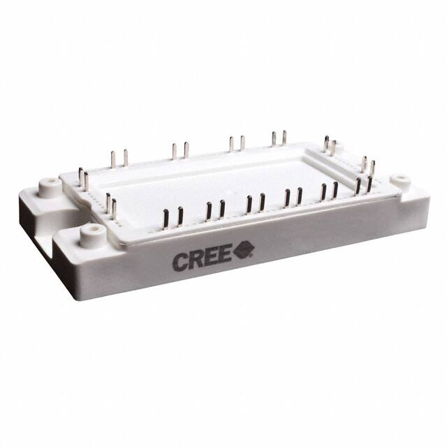
CCS020M12CM2
1200 V, 20 A All-Silicon Carbide
Six-Pack (Three Phase) Module
Technical Features
•
•
•
•
•
•
VDS
1200 V
IDS
20 A
Package 45 mm X 107.5 mm X 20.5 mm
Ultra-Low Loss
High-Frequency Operation
Zero Reverse Recovery from Diodes
Zero Turn-off Tail Current from MOSFET
Normally-off, Fail-safe Device Operation
Copper Baseplate and Aluminum Nitride Insulator
5
4
3
2
1
Applications
•
•
•
•
•
D
3-Phase PFC
Regen Drive
Solar & Renewable Energy
Industrial Automation & Testing
Motor Drive
D
V+
G1
K1
V+
Mid
G3
K3
Mid
G5
K5
Mid
NTC1
G2
K2
C
G4
K4
-t°
G6
K6
NTC2
V-
V-
C
System Benefits
• Fast Time-to-Market with Minimal Development Required for Transition from25, 2645mm IGBT Packages
• Increased System Efficiency, due to Low Switching & Conduction Losses of SiC1
5
9
2
6
10
• Enables Compact and Lightweight Systems
23, 24
21, 22
15, 16
B
B
19, 20
17
3
4
Maximum Parameters (Verified by Design)
Parameter
VDS max
Drain-Source Voltage
VGS max
Gate-Source Voltage, Maximum Value
VGS op
Gate-Source Voltage, Recommended
Op. Value
IDS
DC Continuous Drain-Source Current
ISD
DC Continuous Source-Drain Current
57
IF
Schottky Diode DC Forward Current
49
1
Min.
Typ.
Max.
UnitA
18
13, 14
Test Conditions
Note
A
1200
-10
+25
-5
V
+20
Transient, Ejot DELTA
PT WN 5451 K25x8
: Mmax = 0.4Nm ± 10%
Installation of self-tapping screws can be done both by hand or by using an electric screw driver. For an electric
screw driver the recommended maximum speed is 300 RPM.
(Note: Do not use pneumatic screw driver to install self-tapping screws).
The recommended effective length of screw threads entering the PCB mounting stand-offs should be in between
4mm to 6.5mm range.
(Note: Self-tapping screws must be inserted straight into the PCB mounting stand-offs)
PCB Mounting Stand-offs (Marked Red)
11
Rev. 2, 2020-12-04
CCS020M12CM2
4600 Silicon Dr., Durham, NC 27703
Copyright ©2020 Cree, Inc. All rights reserved. The information in this document is subject to change without notice. Cree®, the Cree logo, Wolfspeed®, and the Wolfspeed logo
are registered trademarks of Cree, Inc.
�Notes
• This product has not been designed or tested for use in, and is not intended for use in, applications implanted into the human
body nor in applications in which failure of the product could lead to death, personal injury or property damage, including
but not limited to equipment used in the operation of nuclear facilities, life-support machines, cardiac defibrillators or similar
emergency medical equipment, aircraft navigation or communication or control systems, or air traffic control systems.
• The SiC MOSFET module switches at speeds beyond what is customarily associated with IGBT-based modules. Therefore, special
precautions are required to realize optimal performance. The interconnection between the gate driver and module housing
needs to be as short as possible. This will afford optimal switching time and avoid the potential for device oscillation. Also, great
care is required to insure minimum inductance between the module and DC link capacitors to avoid excessive VDS overshoot.
12
Rev. 2, 2020-12-04
CCS020M12CM2
4600 Silicon Dr., Durham, NC 27703
Copyright ©2020 Cree, Inc. All rights reserved. The information in this document is subject to change without notice. Cree®, the Cree logo, Wolfspeed®, and the Wolfspeed logo
are registered trademarks of Cree, Inc.
�
很抱歉,暂时无法提供与“CCS020M12CM2”相匹配的价格&库存,您可以联系我们找货
免费人工找货