851 SERIES
Metal Connectors - Rugged - Industry Proven
��851 Series | Introduction
Introduction
•
•
•
•
•
•
Sealing options
Black Zinc Nickel, Nickel plated and Black anodized
Solder and PC tail versions
Thermocouple crimp contacts available
The 851 versions with solder contacts and Zinc Nickel plating (RoHS compliant) is on US QPL
851 connectors are also widely available from distributors.
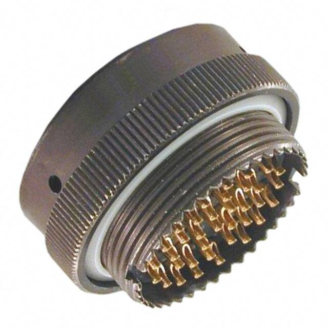
SOURIAU 851 circular connectors were originally developed to ensure reliable electrical connections in aircraft. Due to the lightweight compact
size and general characteristics, the 851-series has been utilized in numerous civil and military aviation applications and also in a multitude of
light and heavy industrial applications (Robotics, Geophysics, Off-Road, Instrumentation, Factory Automation, etc.).
851 connectors conform to the following international standards: MIL-DTL-26482H series 1, NFC 93422, HE 301B, VG 95328, GAM/T1 list.
851 connectors feature a positive bayonet coupling mechanism which ensures reliable mechanical and electrical connection between mating
halves. The plug features a helical locking ring which couples with the three dowel pegs on the receptacle ensuring rapid locking. Orientation
and location is achieved with a system of five raised keys on the plugs which couple with corresponding slots on the receptacles. Connectors
with different angular positioning of the insulator relative to the shell can be provided to prevent undesired accidental mating of adjacent
connectors with the same contact arrangements.
The connector shells are manufactured from aluminum alloy with several finish options. The insulators are molded from elastomer and are
bonded into the shells. Grommets are also made from elastomer and are supplied with appropriate accessories in the solder version. Copper
alloy contacts have gold or tin over nickel plating. To facilitate cabling, we offer solder and PC tail contacts size 20 with a gold plated active
part and tin plated terminations.
Contents
Overview
Typical Applications ..........................................
Features & Benefits ..........................................
Range Overview ...............................................
Ordering Information .......................................
Layouts .............................................................
General Technical Characteristics .....................
Connectors
06
07
08
10
11
12
Receptacles ......................................................
Plugs .................................................................
Harnesses .........................................................
Orientation .......................................................
Cross Reference List .........................................
16
18
23
24
25
3
�851 SERIES
© 2014 SOURIAU - SOURIAU is a registered trademark
�851 Series
Overview
Typical Applications ................................................................................................
06
Features & Benefits ................................................................................................
07
Range Overview .....................................................................................................
08
Ordering Information ..............................................................................................
10
Layouts ...................................................................................................................
11
General Technical Characteristics ...........................................................................
12
5
�851 Series | Overview
Off-Road - Railway
© SOURIAU
Traffic Control Hardware
Fracturing Monitoring
6
Land Aquisition Systems
© Sergey Milovidov / Fotolia
Robotics - Machine Tools
© HappyAlex / Fotolia
Pavers - GPS Systems
© SOURIAU
© SOURIAU
© Rainer Plendl / Fotolia
Typical Applications
�851 Series | Overview
Features & Benefits
500 Mating Cycles
Overview
ENDURANCE
Equipped with a coupling ring made from high strength
aluminum. The plug provides a minimum of 500 mating
unmating cycles. The receptacle is equipped with rugged
stainless steel bayonet pins.
MIL-DTL-26482H
Fully in accordance with the MIL spec requirements.
QUALIFIED
Salt Spray 500 Hours
CORROSION
RESISTANT
Designed to withstand climate ingress and exposure to salt spray
or corrosive atmospheres while still maintaining mechanical and
electrical functionality.
1/3 Bayonet Coupling
QUICK
MATING
With only 1/3 twist of the bayonet coupling system, connectors are
mated with audible "click" and tactile feel to confirm proper mating.
This mating features eliminates connection uncertainty and reduces time
and labor during installation.
Arrangements from 2 to 61 contacts
FLEXIBILITY
Power supply and signal transmission can be combined in a
unique interconnect solution to reduce system complexity and
minimize component/installation costs.
7
�851 Series | Overview
Range
PLUG
Plug with Backnut
06S
Plug with Short Metallic Adaptor and
Plastic Cable Gland
Plug with Straight
Cable Clamp
06L
Plug with Long Metallic Adaptor and
Plastic Cable Gland
Plug with
Adaptor Backnut
06NS
Plug with Right
Angle Cable Clamp
Plug with Short Metallic Adaptor and
Plastic Cable Gland with Spiral Protector
06NL
Plug with Straight
Sealing Gland Backshell
Plug with Long Metallic Adaptor
and Plastic Cable Gland with
Spiral Protector
Overmolded
8
Plug with Straight
Sealing Gland and Cable
Clamp Backshell
�851 Series | Overview
Overview
Overview
06E
06EC
02E
06A
Square Flange
RECEPTACLE
08EC
07A
Jam Nut
06J
06JC
9
�851 Series | Overview
Ordering information
Basic Series
02E
851
8
3A
-
P
5716
Shell type:
02E: square flange receptacle not accepting backshells
07A: jam nut receptacle not accepting backshell
06E: plug with backnut
06EC: plug with straight cable clamp
06A: plug with adaptor backnut
08EC: plug with right angle cable clamp
06J: plug with straight sealing gland backshell
06JC: plug with straight sealing gland and cable clamp backshell
06S: plug with short metallic adaptor and plastic cable gland
06L: plug with long metallic adaptor and plastic cable gland
06NS: plug with short metallic adaptor and plastic cable gland with spiral protector
06NL: plug with long metallic adaptor and plastic cable gland with spiral protector
Shell size:
8 - 10 - 12 - 14 - 16
Contact layouts:
See page 11
Contact type:
P:
male
S:
female
Orientation:
Normal (not included in part number). For others note: w, x, y, z - see table page 24
Obligatory suffix:
Suffix solder
type contact*
See table
below
Suffix PC tail
contact with
shoulder*
See table
below
Suffix PC tail
contact
without shoulder*
See table
below
Black Zinc Nickel
54
1
5416
1
54A7
3
Black Zinc Nickel
57
2
5716
2
-
-
Black Anodized
5029
1
50F9
1
50B3
3
Shell plating
Black Anodized
5129
2
51F9
2
-
-
Nickel
5044
1
5045
1
50G9
3
Nickel
5144
2
5145
2
-
-
Description
1
#20 contact layouts except
8-2, 8-3, 8-4 and 12-4
#16 contact layouts, mix #20, #16 contact layouts and
contacts for 8-2, 8-3, 8-4 and 12-4
Gold plated on active part and tin lead plated
on termination area
2
#20 contact layouts except
8-2, 8-3, 8-4 and 12-4
Gold plated overall
3
All contact sizes and layouts
Gold plated overall
* All contacts are machined
10
Plating
�851 Series | Overview
Layouts
Contact #16 (Ø 1.6 mm)
Contact #20 (Ø 1.0 mm)
8-2
8-3
8-3A/8-98
2 contacts
3 contacts
3 contacts
2xØ1.0 (#20)
3xØ1.0 (#20)
3xØ1.0 (#20)
Mixed Power
Overview
Shell size
8
8-33
8-4
3 contacts
4 contacts
3xØ1.0 (#20)
4xØ1.0 (#20)
10-6
10-98
10-7
6 contacts
6 contacts
7 contacts
6xØ1.0 (#20)
6xØ1.0 (#20)
7xØ1.0 (#20)
10
12
12-2
12-3
2 contacts
3 contacts
2xØ1.6 (#16)
3xØ1.6 (#16)
14-5
14-7
5xØ1.6 (#16)
16
12-8
12-10
12-14
8 contacts
10 contacts
14 contacts
8xØ1.0 (#20)
10xØ1.0 (#20)
14xØ1.0 (#20)
4xØ1.6 (#16)
5 contacts
14
12-4
3 contacts
+ground
6 contacts
+ground
14-18
14-19
14-12
14-15
18 contacts
19 contacts
12 contacts
15 contacts
18xØ1.0 (#20)
19xØ1.0 (#20)
8xØ1.0 (#20)
4xØ1.6 (#16)
14xØ1.0 (#20)
1xØ1.6 (#16)
7xØ1.6 (#16)
16-8
16-26
16-23
8 contacts
26 contacts
23 contacts
8xØ1.6 (#16)
26xØ1.0 (#20)
22xØ1.0 (#20)
1xØ1.6 (#16)
11
�851 Series | Overview
General Technical Characteristics
Materials
• Shell: Aluminum alloy
• Backshells: Aluminum alloy
• Cable glands: Thermoplastic
• Coupling ring: Aluminum alloy
• Coupling spring: Spring stainless steel
• Insert: Elastomeric soft neoprene
• RoHS compliant & conforms to the Chinese
standard SJ/T1166-2006
(Chinese RoHS equivalent)
• Dynamic salt spray:
per EIA-364-26
- 48 h Nickel version
- 500 h Black Anodized version
- 500 h Black Zinc Nickel version
• Insulation resistance
≥ 5000 MΩ under 500 Vcc
• Sealing:
- Globally IP65 (unmated conditions)
- With J or JC backshell IP67 (mated conditions)
- With cable gland IP68 (mated conditions)
Under 10 meter of water during 48 hours
• Contact resistance
- Environmental version:
Size 20 ≤ 4 mΩ / Size 16 ≤ 3 mΩ
• Fluid resistance:
- Hydraulic fluids
- Lubricating oil
• Operating temperature:
from -55°C to +125°C
• Flammability rating:
UL94 HB
12
• Shielding effectiveness:
70 dB to 5 MHz - 40 dB to 100 MHz
Mechanical
Electrical
Environmental
• Current rating per contact
Size 20 = 7.5 A / Size 16 = 13 A
• Dielectric withstanding voltage:
- At standard pressure: mated and unmated
connectors
- 1500 Vrms between size 20 contacts
(service 1)
- 2300 Vrms between size 16 contacts
(service 2)
- 1500 Vrms between mixed size 20 and 16
contacts (service 1)
- At reduced pressure 10 mbar:
connectors mated and unmated
- 200 Vrms between size 20 contacts
(service 1)
- 300 Vrms between size 16 contacts
(service 2)
• Durability:
500 matings and unmatings per
MIL-DTL-26482H
• Vibration resistance:
10-2000 Hz, acceleration 15 g test procedure
per EIA-364-28
• Thermal shock:
5 cycles, 30 min. from -55°C to 125°C
per EIA-364-32
• Mechanical shock:
50 g, 11 ms period per EIA-364-27
�851 Series | Overview
Overview
Notes
13
�851 SERIES
© 2014 SOURIAU - SOURIAU is a registered trademark
�851 Series
Connector
Receptacles
....................................................................................................... 16
Plugs
....................................................................................................... 18
Harnesses
...................................................................................................... 23
Orientation
...................................................................................................... 24
Cross Reference List ....................................................................................................... 25
15
�851 Series | Connector
Receptacles
Square Flange Receptacle not Accepting Backshell, Solder Contact - 02E
E
11.70
maxi
Part numbers
solder contacts
Shell size
8
851 02E 8
10
*
P
S
F
ØA
ØD
L
1.39 maxi
Ø 3.02 mini
L maxi
solder
ØA
maxi
ØD
maxi
E
F
maxi
25.10
12.05
10.87
15.09
21.02
15.01
14.02
18.26
24.22
851 02E 10
P
S
*
25.10
12
851 02E 12
P
S
*
25.10
19.09
17.40
20.62
26.57
14
851 02E 14
P
S
*
25.10
22.27
20.60
23.00
28.92
16
851 02E 16
P
S
*
25.10
25.42
23.75
24.61
31.32
Black anodized* See page 10 "obligatory specification". Example: 85102E123P54
Jam Nut Receptacle not Accepting Backshell, Solder Contact - 07A
P
S
ØA
L
17.90
maxi
Shell size
Part numbers
solder contacts
ØF
L maxi
solder
ØA
maxi
ØF
maxi
P
maxi
S
maxi
8
851 07A 8
25.10
12.05
26.97
19.29
23.97
10
851 07A 10
P
S
*
25.10
15.01
30.17
22.38
26.97
12
851 07A 12
P
S
*
25.10
19.09
34.97
27.13
31.77
14
851 07A 14
P
S
*
25.10
22.27
38.07
30.33
34.97
16
851 07A 16
P
S
*
25.10
25.42
41.27
33.48
38.27
*
P
S
Black anodized* See page 10 "obligatory specification". Example: 85107A123P54
Note: all dimensions are in mm
16
2.67 maxi
�851 Series | Connector
Square Flange Receptacle not Accepting Backshell, PC Tail - 02E
L
T
E
Ø 3.02 mini
F
ØA
ØD
2.36
mini
U
Shell size
Part numbers
PC tail contacts
8
851 02E 8
10
*
P
S
1.39 maxi
L
maxi
ØA
maxi
ØD
maxi
E
F
maxi
20.57
12.05
10.87
15.09
21.02
15.01
14.02
18.26
24.22
851 02E 10
P
S
*
20.57
12
851 02E 12
P
S
*
20.57
19.09
17.40
20.62
26.57
14
851 02E 14
P
S
*
20.57
22.27
20.60
23.00
28.92
16
851 02E 16
P
S
*
20.57
25.42
23.75
24.61
31.32
T (1)
mini
U (2)
mini
9.46
8.68
Connector
11.70
maxi
(1) PC tail contact with shoulder
(2) PC tail contact without shoulder
Black anodized* See page 10 "obligatory specification". Example: 85102E123P54A7
Jam Nut Receptacle not Accepting Backshell, PC Tail - 07A
L
P
2.36 mini
S
ØA
T
U
17.90
maxi
Shell size
Part numbers
PC tail contacts
P
2.67 maxi
ØF
L
maxi
ØA
maxi
ØF
maxi
P
maxi
S
maxi
T (1)
mini
U (2)
mini
9.46
8.68
S
8
20.57
12.05
26.97
19.29
23.97
P
S
*
20.57
15.01
30.17
22.38
26.97
P
P S
S
P
P S
S
*
20.57
19.09
34.97
27.13
31.77
*
20.57
22.27
38.07
30.33
34.97
P
S
*
20.57
25.42
41.27
33.48
38.27
851 07A 8 P
*
P
S
S
10
851 07A 10 P
S
12
851 07A 12
14
851 07A 14
16
851 07A 16
Black anodized* See page 10 "obligatory specification". Example: 85107A123P54A7
(1) PC tail contact with shoulder
(2) PC tail contact without shoulder
Note: all dimensions are in mm
17
�851 Series | Connector
Plugs
Plug with Backnut - 06E
ØA
ØD
L
Shell size
Part numbers
solder contacts
8
851 06E 8
10
12
L maxi
solder
ØA
maxi
*
P
S
ØD
maxi
19.05
13.50
21.80
16.70
26.15
19.90
*
29.35
23.40
*
32.50
26.60
851 06E 10
P
S
*
851 06E 12
P
S
*
14
851 06E 14
P
S
16
851 06E 16
P
S
32.54
Black anodized* See page 10 "obligatory specification". Example: 85106E123P54
Plug with Straight Cable Clamp - 06EC
Shell size
Part numbers
solder contacts
8
851 06EC 8
10
12
*
P
S
L maxi
solder
ØA
maxi
D
maxi
ØG
maxi
48.00
19.05
19.90
3.50
851 06EC 10
P
S
*
48.00
21.80
21.50
5.00
851 06EC 12
P
S
*
48.00
26.15
25.00
8.20
14
851 06EC 14
P
S
*
48.00
29.35
27.80
10.00
16
851 06EC 16
P
S
*
51.00
32.50
29.40
13.00
Black anodized* See page 10 "obligatory specification". Example: 85106EC123P54
Note: all dimensions are in mm
18
D
ØA
ØG
L
�851 Series | Connector
Plug with Adaptor Backnut - 06A
Part numbers
solder contacts
8
851 06A 8
*
P
S
ØD
F
L maxi
solder
ØA
maxi
ØD
maxi
ØG
maxi
UNEF 2A
41.00
19.05
14.50
9.10
1/2 28
threading
10
851 06A 10
P
S
*
41.00
21.80
18.70
12.08
5/8 24
12
851 06A 12
P
S
*
41.00
26.15
21.70
15.25
3/4 20
14
851 06A 14
P
S
*
41.00
29.35
25.10
18.15
7/8 20
16
851 06A 16
P
S
*
41.00
32.50
28.13
21.32
1 20
Connector
Shell size
F
ØA
ØG
L
Black anodized* See page 10 "obligatory specification". Example: 85106A123P54
Plug with Right Angle Cable Clamp - 08EC
ØA
R
L
ØG
Shell size
Part numbers
solder contacts
8
851 08EC 8
10
P
S
*
D
L maxi
solder
ØA
maxi
D
maxi
R
maxi
ØG
maxi
50.10
19.05
19.70
16.00
3.50
21.80
21.20
18.00
5.00
851 08EC 10
P
S
*
52.60
12
851 08EC 12
P
S
*
54.90
26.15
24.20
19.50
8.20
14
851 08EC 14
P
S
*
58.50
29.35
27.50
22.00
10.00
16
851 08EC 16
P
S
*
60.80
32.50
29.10
23.50
13.00
Black anodized* See page 10 "obligatory specification". Example: 85108EC123P54
Note: all dimensions are in mm
19
�851 Series | Connector
Plugs (Continued)
Plug with Straight Sealing Gland Backshell - 06J
ØA
Part numbers
solder contacts
Shell size
8
851 06J 8
10
12
*
P
S
ØD
ØG
L
ØG
L maxi
solder
ØA
maxi
ØD
maxi
mini
maxi
47.60
19.05
14.40
5.02
5.84
851 06J 10
P
S
*
47.60
21.80
17.60
5.94
6.76
851 06J 12
P
S
*
49.20
26.15
21.10
9.34
10.16
14
851 06J 14
P
S
*
54.00
29.35
24.40
11.32
12.14
16
851 06J 16
P
S
*
59.60
32.50
27.60
14.73
15.55
Black anodized* See page 10 "obligatory specification". Example: 85106J123P54
Plug with Straight Sealing Gland and Cable Clamp Backshell - 06JC
Shell size
Part numbers
solder contacts
P
S
ØG
L maxi
solder
ØA
maxi
ØD
maxi
mini
maxi
8
851 06JC 8
57.68
19.05
19.90
5.02
5.84
10
851 06JC 10
P
S
*
57.68
21.80
21.50
5.94
6.76
851 06JC 12
P
S
*
61.24
26.15
25.00
9.34
10.16
14
851 06JC 14
P
S
*
66.01
29.35
27.80
11.32
12.14
16
851 06JC 16
P
S
*
74.75
32.50
29.40
14.73
15.50
12
*
Black anodized* See page 10 "obligatory specification". Example: 85106JC123P54
Note: all dimensions are in mm
20
ØD
ØA
ØG
L
�851 Series | Connector
Plugs with Metallic Adaptor and Plastic Cable Glamp
Plug with Short Metallic Adaptor and Plastic Cable Gland - 06S
B
Part numbers
solder contacts
8
851 06S 8
10
12
*
P
S
ØG
A
maxi
B
maxi
ØC
maxi
mini
maxi
37.00
61.00
19.30
4.00
5.00
851 06S 10
P
S
*
37.00
64.00
22.00
4.00
6.00
851 06S 12
P
S
*
37.00
66.00
26.30
4.00
7.00
14
851 06S 14
P
S
*
37.00
67.00
29.50
4.00
9.00
16
851 06S 16
P
S
*
42.00
75.00
32.70
6.00
12.00
Connector
Shell size
ØG
ØC
A
Black anodized* See page 10 "obligatory specification". Example: 85106S123P54
Plug with Long Metallic Adaptor and Plastic Cable Gland - 06L
E
Shell size
Part numbers
solder contacts
ØG
ØC
D
ØG
D
maxi
E
maxi
ØC
maxi
mini
maxi
8
851 06L 8
57.00
81.00
19.30
4.00
5.00
10
851 06L 10
P
S
*
57.00
84.00
22.00
4.00
6.00
12
851 06L 12
P
S
*
57.00
86.00
26.30
4.00
7.00
14
851 06L 14
P
S
*
57.00
87.00
29.50
4.00
9.00
16
851 06L 16
P
S
*
57.00
90.00
32.70
6.00
12.00
*
P
S
Black anodized* See page 10 "obligatory specification". Example: 85106L123P54
Note: all dimensions are in mm
21
�851 Series | Connector
Plugs with Metallic Adaptor and Plastic Cable Glamp (Continued)
Plug with Short Metallic Adaptor and Plastic Cable Gland with Spiral Protector - 06NS
B
ØC
ØG
A
Shell size
8
Part numbers
solder contacts
851 06NS 8
*
P
S
ØG
A
maxi
B
maxi
ØC
maxi
mini
maxi
37.00
91.00
19.30
4.00
6.50
10
851 06NS 10
P
S
*
37.00
101.00
22.00
4.00
7.00
12
851 06NS 12
P
S
*
37.00
114.00
26.30
4.00
7.00
851 06NS 14
P
S
*
37.00
125.00
29.50
4.00
7.00
851 06NS 16
P
S
*
42.00
144.00
32.70
6.00
11.0
14
16
Black anodized* See page 10 "obligatory specification". Example: 85106NS123P54
Plug with Long Metallic Adaptor and Plastic Cable Gland with Spiral Protector - 06NL
E
Shell size
Part numbers
solder contacts
ØG
ØC
D
E
maxi
ØC
maxi
mini
maxi
8
851 06NL 8
57.00
111.00
19.30
4.00
6.50
10
851 06NL 10
P
S
*
57.00
121.00
22.00
4.00
7.00
12
851 06NL 12
P
S
*
57.00
134.00
26.30
4.00
7.00
14
851 06NL 14
P
S
*
57.00
145.00
29.50
4.00
7.00
16
851 06NL 16
P
S
*
57.00
159.00
32.70
6.00
11.0
*
P
S
Black anodized* See page 10 "obligatory specification". Example: 85106NL123P54
Note: all dimensions are in mm
22
ØG
D
maxi
�851 Series | Connector
Harnesses
Connector
• Shielded metal connector
• Sealing: IP68 mated
• 4 layouts: (8-4/10-6/12-10/14-19)
• Other layouts on request, consult us
• Rapid 1/3 turn coupling
• Conforms to the international standard
MIL-DTL-26482H series 1
Cable
• TPE outer sheath (black color)
• Multi-conductor 10, 12 or 14
• 300V
• Shielded
• Flammability rating UL 1581
Sec.1080 (VW-1)
• Resistant to a wide range of chemical
fluids
Plating
Salt spray
Temperature
Sealing Mated
Mechanical
Black Zinc Nickel
500 H
-55° C up to + 125° C
IP68
500 matings unmatings
Black Anodized
500 H
-55° C up to + 125° C
IP68
500 matings unmatings
Nickel
48 H
-55° C up to + 125° C
IP68
500 matings unmatings
Connector
Applications
• Instrumentation & measurement
• Industrial robots
• Machine tools
• Off-Road
• Mining
Shielding
70 dB
With appropriate cable and overmold
23
�851 Series | Connector
Orientation
Insulator Rotated Inside Metal Body
Viewed from front face of male
insulator (receptacle or plug)
Shells
8
10
12
14
16
Layouts
W
X
Y
Z
#16
1500 Vrms
#20
2300 Vrms
2
58
122
-
-
X
-
3
60
210
-
-
X
-
3A (98)*
60
210
-
-
X
-
4
45
-
-
-
X
-
33
90
-
-
-
X
-
6
90
-
-
-
X
-
7*
90
-
-
-
X
-
98
90
180
240
270
X
-
2
-
-
-
-
-
X
3
-
-
180
-
-
X
4
-
-
-
-
X
-
8
90
112
203
292
X
-
10
60
155
270
295
X
-
14*
45
5
40
92
184
273
X
-
-
X
7
-
-
-
-
X
-
12
43
90
-
-
X
-
15
17
110
155
234
X
-
18
15
90
180
270
X
-
19
30
165
315
-
X
-
8
54
152
180
331
-
X
23
158
270
-
-
X
-
26
60
-
275
338
X
-
* 8-98 layout, W and X non standard ortientations
10-7 & 12-14 layouts, W non standard orientation
24
Angle in degrees
�851 Series | Connector
Cross Reference List
SOURIAU
MIL-DTL-26482H Series 1
851 00 E .. .. .. 54/57
MS 3110 E .. .. ..K
851 00 EC .. .. .. 54/57
MS 3110 F .. .. ..K
851 00 AC .. .. .. 54/57
-
851 00 P .. .. .. 54/57
MS 3110 P .. .. ..K
851 00 A .. .. .. 54/57
-
851 00 J .. .. .. 54/57
-
851 00 JC .. .. .. 54/57
MS 3110 J .. .. ..K
851 01 E .. .. .. 54/57
MS 3111 E .. .. ..K
851 01 EC .. .. .. 54/57
MS 3111 F .. .. ..K
851 01 AC .. .. .. 54/57
-
851 01 P .. .. .. 54/57
MS 3111 P .. .. ..K
851 01 A .. .. .. 54/57
-
851 01 J .. .. .. 54/57
-
851 01 JC .. .. .. 54/57
MS 3111 J .. .. ..K
851 02 E .. .. .. 54/57
MS 3112 E .. .. ..K
851 06 E .. .. .. 54/57
MS 3116 E .. .. ..K
851 06 EC .. .. .. 54/57
MS 3116 F .. .. ..K
851 06 AC .. .. .. 54/57
-
851 06 P .. .. .. 54/57
MS 3116 P .. .. ..K
851 06 A .. .. .. 54/57
-
851 06 J .. .. .. 54/57
-
851 06 JC .. .. .. 54/57
MS 3116 J .. .. ..K
851 08 EC .. .. .. 54/57
-
851 08 P .. .. .. 54/57
-
851 07 E .. .. .. 54/57
MS 3114 E .. .. ..K
851 07 EC .. .. .. 54/57
MS 3114 F .. .. ..K
851 07 AC .. .. .. 54/57
-
851 07 P .. .. .. 54/57
MS 3114 P .. .. ..K
851 07 A .. .. .. 54/57
-
Connector
851 Version with Solder Contacts (Black Zinc Nickel)
25
�851 Series | Connector
Notes
26
��Our contribution to environmental
protection:
This catalog is printed on PEFC
certified paper
Advancement of sustainable
wood cultivation. www.pefc.org
www.souriau-industrial.com
contactindustry@souriau.com
CA851INDUSWUSEN01 © Copyright SOURIAU 2014 - SOURIAU is a registered trademark
All information in this document presents only general particulars and shall not form part of any contract. All rights reserved to SOURIAU for changes without prior notification or public announcement. Any duplication is prohibited, unless approved in writing. Photos: Fotolia.com
Your local contact
�
很抱歉,暂时无法提供与“MS3116J2236P”相匹配的价格&库存,您可以联系我们找货
免费人工找货