Page 1 of 15
Binary Blaster Assembly Guide
Introduction
Binary Blaster is a game that helps teach the player how to count in binary
as well as convert from decimal (and hexadecimal) to binary and back,
quickly. It displays a value on the 7 segment display, and the player is
challenged to press the buttons in a way that represents the binary
equivalent. Press a button to “set” that bit. Leave a button alone to “clear”
that bit. There are four buttons, each one represents a bit. This means
there are 15 possibilities. If the player gets all 15 correct, they win! It also
displays a time score, so you can keep track of your fastest speed and
practice to get faster!
This product comes as a PTH soldering kit, and it’s up to you to solder it all
together! You can buy the complete kit here.
If you’re new to soldering, the Binary Blaster PTH Kit is a great place to
start. This assembly guide will take you through each component in the kit
and show you how to solder it into place.
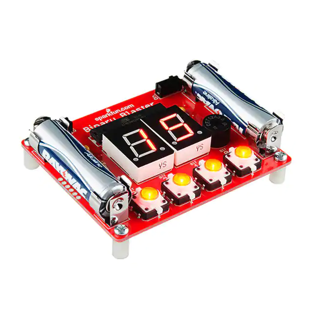
The assembled Binary Blaster PTH Kit
Necessary tools and supplies
• Soldering Iron
• Solder
• Cutters
Suggested additional tools and supplies
•
•
•
•
•
Safety Glasses
Flux Pen
Solder Wick
Scrubbing brush (an old toothbrush works fine)
Dionized water for cleaning (or you can get away with tap water)
�Page 2 of 15
Suggested Reading
If you’d like more general knowledge about PTH soldering, then we suggest
checking out these following other tutorials:
•
•
•
•
•
How to Solder - Through-hole Soldering
Decoding Resistor Markings
Diode and LED Polarity
Electronics Assembly - Washing
Video - SparkFun Infrared Sensor Overview
QuickStart - Your First Component
Locate the 10KΩ Resistor. It has a specific pattern of stripes on it: BROWN,
BLACK, ORANGE, GOLD.
It looks like this:
Note, the patten can be in the opposite order; this is still the correct resistor.
To further understand resistor markings, please check out the following
tutorial: Decoding Resistor Markings
Bend the legs downward.
Locate the 10KΩ Resistor position on the board.
Insert the resistor into the PCB. Note, this component is not polarized, so it
does not matter which leg goes into each hole. Some components on this
kit are polarized, and we will take extra care when we get to them to ensure
they are plugged in properly.
�Page 3 of 15
Push the resistor in so it is nearly flush with the board.
Slightly bend the legs outward to hold it in place.
Flip the board over. Hold the soldering iron’s “Sweet Spot” so it touches
both the leg and the metal ring. Hold for 2 seconds.
Feed solder into the joint.
First, pull away the solder.
�Page 4 of 15
Second, pull away the iron.
Your solder joints should look like this:
Clip off any excess legs.
Capacitors
Locate the two 0.1uF capacitors. These look a little different than resistors.
They have two leads than come down off the bottom of the component, and
they have the markings “104” on them. Also note, the bottom side may
have some other letters, like “K5M.”
They look like this:
�Page 5 of 15
Locate their positions on the PCB:
Ensure that they are flush with the surface of the PCB and standing upright.
Solder them into place and clip access lead length. When you’re done
soldering these into place, your board should look like this:
The Microcontroller
Locate the microcontroller. This particular microcontroller is an
ATmega328. This component is polarized, which means we need to take
extra care to place it in the board properly. Notice the notch:
Now, locate the position on the PCB. Again, notice a similar notch symbol
in the PCB white ink:
�Page 6 of 15
Taking care to align the notch properly, place the ATmega328 into the PCB.
While soldering the first leg (it can be any leg you choose), make sure to
keep the component flush with the PCB.
When you’re done soldering this component, the bottom of your board
should look like this - a nice row of even volcanos:
Buzzer and Switches
Locate the buzzer and slide switches:
Locate the positions on the PCB:
�Page 7 of 15
Place your components in the PCB. Flip it over, and solder them into place.
When you are done, you’re PCB should look like this:
Light-up Buttons
Locate the 4 LED tactile buttons:
These buttons are polarized. Notice the small “+” sign on the top side of the
white plastic leg:
Locate the 4 positions on the PCB:
�Page 8 of 15
Note the polarity markings on the PCB. Make sure the “+” side on the
button aligns with the “+” marking on the PCB:
Solder into place. When you are done, your board should look like this:
7-segment Displays
Locate the 2 7-Segment Displays:
These displays are polarized. Notice the decimal points below the digits:
�Page 9 of 15
Locate the 2 positions on the PCB:
Note the polarity markings on the PCB. Make sure the decimal dots on the
displays align with the decimal markings on the PCB. Solder into place.
When you are done, your board should look like this:
Battery Clips
Locate the 4 Battery Clips:
Locate the 4 positions on the PCB:
�Page 10 of 15
Note, these parts are polarized and must be soldered in so the back sides
are facing out. If placed incorrectly, the batteries will not fit. Ensure they are
flush and that the back sides are facing out:
Solder into place. When you are done, your board should look like this:
Standoffs
Locate the 4 Plastic Standoffs and 4 metal screws:
Note: you do not need a screwdriver to place these into the PCBs. Hand
tightening should suffice.
With the standoffs installed, your Binary Blaster should rest flat on the table:
�Page 11 of 15
Batteries
Locate the two AA batteries:
These are polarized, so make sure to align the “+” and “-” sides correctly:
Place the batteries into the clips, and turn it on to check that they are in
correctly. You should see the LED tactile buttons light up to show you that
the batteries are plugged in correctly and your Binary Blaster is powering
up.
How to Play the Game
First, turn on your Binary Blaster. The power slide switch is located on the
top left side of the PCB. Slide it to the “ON” position - to the left.
You may also want to check the sound switch. You can slide this to either
the left or right, depending on if you would like to play with sound or not.
If nothing happens, it may be that your batteries are placed incorrectly.
Please make sure to double check the polarity.
When you first power up your Binary Blaster, you should notice that the
buttons light up quickly from right to left, and then the display begins
blinking a circular pattern. These blinks are part of “boot up” in order to
ensure that the LEDs and displays are working properly.
While the displays are blinking the circular pattern, your Binary Blaster is
ready to begin a new game.
To begin a new game, simply press one of the buttons.
The display will now show you your first value. Note, this can be different
�Page 12 of 15
every time.
You must now press the binary equivalent on the four buttons. Here is a
chart to help you get started:
“1” = 0001
“2” = 0010
“3” = 0011
“4” = 0100
“5” = 0101
“6” = 0110
“7” = 0111
“8” = 1000
“9” = 1001
“10” = 1010
“11” = 1011
“12” = 1100
“13” = 1101
“14” = 1110
“15” = 1111
Here’s a few examples to help show how the buttons work.
Example 1:
If you see the number “1” on the display, then you must press the binary
equivalent, which is “0001”. This means that you must press the “BIT 0”
button (this is the button furthest to the right). You must also leave the other
three buttons alone (don’t press them!) In this way, you are setting only the
“BIT 0” (aka making it a “1” instead of leaving it a “0”).
Example 2:
If you see the number “2” on the display, then you must press the binary
equivalent, which is “0010”. This means that you must press the “BIT 1”
button (this is the middle-rightside button). In this way, you are setting this
bit (aka making it a “1” instead of leaving it a “0”).
Example 3:
If you see the number “5” on the display, then you must press the binary
equivalent, which is “0101”. This means that you must press the “BIT 0”
and the “BIT 2” button at the same time.
If you do not press the correct value within a few seconds, the Binary
Blaster will time out, and this effectively means you have lost this round. To
start another, simply press any button.
When you press the correct binary equivalent, then you will move on to the
next random value. There are 15 total. Once you convert all 15 (without
timing out) you have won!
Each time you begin a new game, the order will be different. It does this to
help encourage learning conversion rather than muscle memory of a
pattern. Also, when you have completed all 15 possibilities, the display will
show you your “score”. This is the amount of seconds it took you to
complete the game. As you practice your conversions, you should be able
to get this number lower and lower. Good luck!!
�Page 13 of 15
When you have mastered the default playing mode (decimal conversion),
you may like to challenge yourself to convert from hexadecimal notation to
binary. In hexadecimal mode, your Binary Blaster will display the values 1015 in hexadecimal. Note, the lower values (1-9) will still be shown as
decimal values, because these are the same in both value notations.
HexadecimalMode
To play in Hexadecimal mode, follow these three steps:
(1) Turn your Binary Blaster off.
(2) Press and hold the “BIT 0” button.
(3) While continuing to hold the “BIT 0” button, turn your Binary Blaster
back on again. You should see the display show “A b C d E F”. You are
now in hexadecimal mode. To go back to default decimal mode, simply
cycle power without any buttons pressed.
Here is a hexadecimal chart to help you get started:
“1” = 0001
“2” = 0010
“3” = 0011
“4” = 0100
“5” = 0101
“6” = 0110
“7” = 0111
“8” = 1000
“9” = 1001
“A” = 1010
“b” = 1011
“C” = 1100
“d” = 1101
“E” = 1110
“F” = 1111
We hope you enjoy your Binary Blaster. After a bit of practice, please feel
free to post your best score in the discussion area of this tutorial. Thanks
for your support of SparkFun and have fun blasting binary values!
Troubleshooting Buttons
Is one of your buttons not lighting up? Don’t fret, there is an easy way to fix
it! The most common cause of a failing LED is incorrect polarity. We have
designed a special trick into the Binary Blaster PCB to fix this. You can
simply cut the two traces, and close two jumpers. This will swap the polarity
without having to remove the button.
First, find the solder jumpers next to the button you are troubleshooting.
There are two jumpers per button. They are located on the bottom side of
the PCB, near each button.
�Page 14 of 15
Each jumper has a small trace connecting the middle pad to the default
polarity setting. The small trace is sometimes difficult to see, but it is a thin
stripe of metal that should show up as a lighter color red. Using a hobby
knife (aka x-acto knife), cut the default traces:
Using your soldering iron, close a jumper between the middle pad and the
other outside pad:
The polarity of the traces running to that LED should now be swapped, and
your LED should be lighting up.
Resources and Going Further
If you’d like to further understand how the Binary Blaster design works, a
good place to start is looking at the design files. You can get the complete
hardware and firmware files at the GitHub Repository here:
• Binary Blaster GitHub Repo
Your Binary Blaster game is re-programmable with Arduino. This means
that you can change the rules of the game, add more features, or turn it into
a completely different project. For more information about how to reprogram using Arduino, check out this following tutorial:
• What is an Arduino?
If it’s more soldering that you’re after, here are a few suggestions for other
fun PTH soldering kits:
• Simon Tilts - Through Hole Soldering Kit
�Page 15 of 15
• ClockIt
• Simon Says - Through-Hole Soldering Kit
To see all of the Kits we offer on our website, checkout our Kits Category
on the SparkFun website.
If you’re interested to learn more about writing code, a good place to start is
by completing the example circuits in the SparkFun Inventors Kit.
The microcontroller included with your Binary Blaster is actually reprogramable with Arduino. This is the same microcontroller that is used in
the RedBoard SIK. This means that if you wanted to, you could use the
skills learned in the SIK to modify your Binary Blaster. For example, you
could change the way the game plays or use it for an entirely different
project!
https://learn.sparkfun.com/tutorials/binary-blaster-assembly-guide?_ga=1.106769859.11809... 8/5/2016
�


 工商网监
湘ICP备2023018690号
工商网监
湘ICP备2023018690号