nRFgo Development Kit
nRF2460
User Guide v1.0
All rights reserved.
Reproduction in whole or in part is prohibited without the prior written permission of the copyright holder.
2011-6-24
�nRF2460 Development Kit User Guide
Liability disclaimer
Nordic Semiconductor ASA reserves the right to make changes without further notice to the product to
improve reliability, function or design. Nordic Semiconductor ASA does not assume any liability arising out
of the application or use of any product or circuits described herein.
Life support applications
These products are not designed for use in life support appliances, devices, or systems where malfunction
of these products can reasonably be expected to result in personal injury. Nordic Semiconductor ASA
customers using or selling these products for use in such applications do so at their own risk and agree to
fully indemnify Nordic Semiconductor ASA for any damages resulting from such improper use or sale.
Contact details
For your nearest dealer, please see http://www.nordicsemi.com
Receive available updates automatically by subscribing to eNews from our homepage or check our
website regularly for any available updates.
Main office:
Otto Nielsens veg 12
7004 Trondheim
Phone: +47 72 89 89 00
Fax: +47 72 89 89 89
www.nordicsemi.com
Revision History
Date
June 2011
Revision 1.0
Version
1.0
Description
Page 2 of 13
�nRF2460 Development Kit User Guide
Contents
1
Introduction .................................................................................................4
1.1
Who should read this user guide? ........................................................4
1.2
Minimum requirements .........................................................................4
1.3
Writing conventions ..............................................................................4
2
Development Kit content ............................................................................5
2.1
Hardware content ...............................................................................5
2.2
Software content...................................................................................6
2.3
Documentation......................................................................................6
3
Typical usages.............................................................................................7
3.1
Setting up for product evaluation ..........................................................7
3.1.1
How to program the nRF2460 module .............................................7
3.2
Setting up for prototype development...................................................8
3.2.1
Connecting an external MCU ...........................................................8
3.2.2
Connecting an external codec..........................................................8
3.3
Running stand alone.............................................................................8
3.4
Audio performance measurement ........................................................9
3.5
Current consumption measurement .....................................................9
3.6
Measuring RF parameters ....................................................................9
4
Hardware description..................................................................................10
4.1
nRF2460 module connectors (bottom side).........................................10
4.2
Module I/O port headers (top side) .......................................................10
4.2.1
Digital audio interface.......................................................................10
4.2.2
Slave control interface......................................................................11
4.2.3
Audio operation mode ......................................................................11
4.2.4
Stand-alone operation ......................................................................11
4.3
Block schematic....................................................................................12
5
Troubleshooting ..........................................................................................13
Revision 1.0
Page 3 of 13
�nRF2460 Development Kit User Guide
1
Introduction
The nRF2460 Development Kit is the recommended starting point for developing a new product based on
the nRF2460 Wireless Mono Audio Streamer. The nRF2460-DK used in conjunction with the nRFgo
Starter Kit (sold separately) is the ideal platform to help you through each stage of the development
process. The nRF modules of the nRF2460-DK can run stand-alone with external power supply for simple
evaluation, or placed into an nRF module socket on an nRFgo Starter Kit Motherboard to evaluate all the
features of the nRF2460. Available headers on the nRF2460-DK make it easy to connect an external audio
codec or MCU while developing a product.
1.1
Who should read this user guide?
Anyone developing a product based on the nRF2460 should read this User Guide. It describes all the
features of the nRF2460 Development Kit from how to use the pre-compiled firmware in order to evaluate
the nRF2460 module, to how to connect external MCU or codec during prototyping of your own hardware.
To fully understand this User Guide a background in software development and/or electronic engineering is
required.
1.2
Minimum requirements
Minimum requirements for using the nRF2460 Development Kit are:
•
•
•
1.3
nRFgo Starter Kit
Computer with 2 USB ports
Windows XP, Windows 7
Writing conventions
This user guide follows a set of typographic rules to make the document consistent and easy to read. The
following writing conventions are used:
•
•
•
Commands are written in Courier New bold.
File names and User Interface components are written in regular bold.
Cross references are underlined and highlighted in blue.
Revision 1.0
Page 4 of 13
�nRF2460 Development Kit User Guide
2
Development Kit content
The nRF2460 Development Kit is based on the nRFgo development platform, and consists of nRF
modules that can be plugged into an nRFgo Starter Kit Motherboard during development and evaluation.
You can download all the necessary software and documentation from Nordic Semiconductor’s website at
www.nordicsemi.com.
The nRFgo compatible nRF2460 Development Kit contains the hardware, software and documentation
components outlined in sections 2.2 and 2.3.
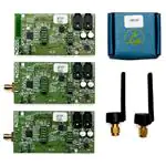
Figure 1. Kit content
2.1
Hardware content
The nRF2460 Development Kit consists of one nRF2460 module with a PCB antenna, two nRF2460
modules with an SMA connector, two external 2.4 GHz swivel antennas, and five samples of the nRF2460
IC (integrated circuit).
Revision 1.0
Page 5 of 13
�nRF2460 Development Kit User Guide
2.2
Software content
You can download the software package from www.nordicsemi.com. The software package includes:
•
•
nRFgo Studio software
Pre-compiled firmware for the nRF2460-DK (including source code)
In addition we recommend that you install the KeilTM C51 C compiler (an evaluation version is available)
from www.keil.com for writing custom firmware to the nRF module.
2.3
Documentation
The main source of documentation for the nRF2460 module is the product specification for the nRF2460,
which contains a complete description of all registers, the application schematic, and a Bill of Materials. In
addition the reference layout files for the nRF2460 are available for download from www.nordicsemi.com.
The Development Kit’s documentation includes:
•
•
•
This User Guide
Getting Started Guide
Application note “Creating applications with the KeilTM C51 C compiler”
Revision 1.0
Page 6 of 13
�nRF2460 Development Kit User Guide
3
Typical usages
The nRF2460 Development Kit is designed to simplify the testing of features and performance in the
nRF2460 in different environments and during prototype development.
By default, the nRF modules are pre-programmed from factory to stream audio from the line-in input on the
audio source, to the headset output on the audio destination. Setup for demonstration purposes is
described in the Getting Started Guide nRFgo Development Kit nRF2460.
Typically, when evaluating a new product, the developer wants to find the typical range of the product and
the audio performance in the environments for which the product is planned to operate. Moreover he or
she wants to know the power consumption in order to calculate the expected battery lifetime. All this is
possible by using pre-compiled firmware.
However during prototype development you will connect the nRF2460 module to your own hardware. If
you prefer to use a different MCU or codec instead of those already located on the nRF module, you can
make all the digital interfaces for the nRF2460 available on headers on the nRF2460 module.
3.1
Setting up for product evaluation
To evaluate the nRF2460 device with custom configuration, meaning custom latency, hopping table or
audio format, the on-board nRF24LE1 must be programmed with new, application firmware from the
example projects for the nRF2460 Development Kit.
The nRF module is fitted with an nRF24LE1 to configure and use the nRF2460 through a slave I2C control
interface. The nRF24LE1 is a System-on-Chip solution with an embedded Nordic Semiconductor radio and
an 8051 MCU. However, for this nRF module only the embedded 8051 MCU is used to set up the
nRF2460, and this module will show up as an nRF24LE1 module in the nRFgo Studio Device Manager
pane.
You must download the nRFgo Studio in order to program the nRF module with any of the pre-compiled
firmware files. See chapter 4 on page 10. and the help file in nRFgo Studio for more information on usage.
Refer to the application note “Creating Applications with the KeilTM C51 C Compiler” if you want to write
custom firmware based on the source code for the nRF2460-DK.
3.1.1
How to program the nRF2460 module
This section describes how to program an nRF2460 module from the software application nRFgo Studio to
evaluate your nRF2460 device for your end product.
1.
2.
3.
4.
5.
6.
7.
8.
9.
10.
Turn the nRFgo Motherboard off by switching the S9 to OFF.
Plug an nRF2460 module with the PCB antenna (or with the SMA connector and an external
antenna) onto the module connector on the nRFgo Starter Kit Motherboard. Position the module
so the antenna is leading out from the Motherboard.
Connect the nRFgo Motherboard to your computer using a USB cable.
Turn the nRFgo Starter Kit Motherboard power on by switching S9 to ON.
Download the latest version of nRFgo Studio from www.nordicsemi.com onto your computer.
Start the nRFgo Studio from the Windows Start menu - Programs - Nordic Semiconductor nRFgo Studio.
In nRFgo Studio, select Motherboards in the Device Manager pane and then select Module .
Select the precompiled file you want to download to nRF24LE1 for programming.
Click the Program button.
Turn the Motherboard OFF and ON again for the configuration of nRF2460 to take effect.
Revision 1.0
Page 7 of 13
�nRF2460 Development Kit User Guide
Now that you have configured the nRF2460 you can set up application-specific tasks during audio
streaming, like a mute, general purpose data transfer and power down from the nRF24LE1 application
firmware.
Firmware
nRF2460-DK.hex
nRF2460-Medium.hex
Test-TX-Sweep.hex
Test-RX-Sweep.hex
Description
Sets up the nRF2460 to stream audio with high latency
(default)
Sets up the nRF2460 to stream audio with medium
latency
RF test mode that sets up the nRF2460 to TX channel
sweep
RF test mode that sets up the nRF2460 to RX channel
sweep
Table 1. Pre-compiled firmware available for the nRF2460-DK
For your development needs, you can re-configure the nRFmodule in two ways. You can either use the
nRFgo Studio software to program pre-compiled firmware, or connect an external MCU or codec directly to
the nRF module headers. The nRFgo Studio is typically used for evaluation of the product, while external
MCUs or codecs will normally be used during prototype development.
3.2
Setting up for prototype development
When developing a prototype, you need not program the nRF2460 module. However, you will need to set
up an external MCU or codec.
3.2.1
Connecting an external MCU
To connect an external MCU, you must first remove the jumpers on header P7. The P7 header gives direct
access to slave control I2C or SPI of the nRF2460. Refer to section 4.2.2 on page 11 for full description of
pin-out of the headers. For reference when setting up the external MCU for developing your own prototype,
the source code for the nRF module and the nRF2460 Product Specification are two good starting points.
3.2.2
Connecting an external codec
To connect an external codec, you must first remove the jumpers on header P10. The P10 header gives
direct access to the I2S audio interface. Refer to section 4.2.3 on page 11 for full description of pin-out of
the headers. For reference when setting up the external codec for developing your own prototype, the
source code for the nRF module and the nRF2460 Product Specification are two good starting points.
3.3
Running stand alone
The nRF module can run stand-alone meaning you have already programmed the nRF module and
removed it from the nRFgo Starter Kit Motherboard. In order to run stand alone, connect the external
power supply (two AAA batteries) to headers P4 and P8. Refer to section 4.2.4 on page 11 for details on
voltage requirements and pin-out.
The nRF modules come in two variants, one with a PCB antenna and one with an SMA connection for
external antenna. The radiation pattern of antennas depends heavily on the layout of the antenna, the
ground size, casing, and placement. This means that the actual range when running stand-alone depends
on how the board is placed and oriented. Typically, when designing a product, you should make the design
such that the radiation pattern of the antenna is oriented towards the other nRF module. This is especially
important if the module is stationary, since antennas can easily have a difference in gain of 10 to 15dB in
different directions.
Revision 1.0
Page 8 of 13
�nRF2460 Development Kit User Guide
3.4
Audio performance measurement
The nRF2460 features a digital I2S interface for transparent audio streaming between source and
destination, and any loss in audio will be experienced as a soft mute for a minimum of 16 audio samples
(500 μs).
Since the interface is digital you are not able to measure any typical analog performance, such as THD or
SNR for the audio. However, you are able to use the analog interface (mini-jack connectors) of the nRF
module to measure loss in audio across time. This will enable you to evaluate the audio performance for
the nRF2460 in different environments and ranges.
A typical way to evaluate the audio performance is to use the analog interface and set up the audio source
with a continuous, fixed audio tone, such as 1 kHz, and then record the audio on the destination side.
Afterwards, you must filter the recording, using for instance a 1 kHz notch filter, to view the number of times
you experience audio loss.
Many websites offer evaluation versions of software for audio filtering. An example of such software is the
AVS audio editor. Make sure that the test tone lasts long enough for the entire recording.
3.5
Current consumption measurement
You can measure the current consumption in two ways, depending on whether the nRF module is running
stand-alone or not.
If the nRF module is plugged into the nRFgo Starter Kit Motherboard, then you can measure current by
connecting a multimeter to the nRF Current Measurement header on the nRFgo Starter Kit Motherboard. If
the nRF module is running stand-alone, then you can measure current directly by placing a multimeter in
series with the external power supply on header P4.
3.6
Measuring RF parameters
To measure the output power, RX LO leakage and harmonics, the nRF module with an SMA connector
must be programmed with RF test firmware. The nRF module should then be connected to a spectrum
analyzer for measurement.
Note that the nRF2460 does not support a test mode for measuring the sensitivity limit (BER or PER)
directly. A typical way to measure sensitivity is to use two nRF modules with an SMA connector, program
them with the default firmware (nRF2460-DK.hex) and attach a step attenuator between the modules.
Increase the attenuation until there is audio loss. The sensitivity limit is now the sum of the attenuator
setting, cables and connectors.
Revision 1.0
Page 9 of 13
�nRF2460 Development Kit User Guide
4
Hardware description
The nRF2460-DK consists of nRFgo radio modules with a common analog input and output (3.5mm minijacks), for easy connection to MP3 players and headphones. All digital interfaces, such as the I2S audio,
and slave SPI or I2C control interface, are available on headers for easy connection to a third-party MCU
or codec during development.
The nRF2460 modules come in two variants, one with a ready-made PCB antenna, and another with an
SMA connection. You can set up both variants to work as an audio transmitter (source) or receiver
(destination).
4.1
nRF2460 module connectors (bottom side)
The nRF2460 module bottom side connectors (header P5 and P6), have all I/Os required for
communicating with the nRFgo Starter Kit Motherboard. By placing the nRF2460 module into the nRFgo
Motherboard socket, you can program and develop customized firmware for the on-board nRF24LE1.
The pin out for the module connector is documented in the User Guide for the nRFgo Starter Kit.
4.2
Module I/O port headers (top side)
The top side I/O headers enable you to connect a third-party MCU and codec, or run the nRF module
stand-alone by connecting external power supply. The I/O headers are split into four main categories for
easy connection during development.
4.2.1
Digital audio interface
All I/Os for the digital I2S audio interface are available directly on the nRF module (Header P10). By
removing the jumpers across the pin header, you are able to directly connect a third-party codec, ADC or
DAC.
nRF2460 (left side) Codec (right side)
MCLK
MCLK
DATA
DATA
WS
WS
CLK
CLK
Table 2. Audio header pin (header P10)
Revision 1.0
Page 10 of 13
�nRF2460 Development Kit User Guide
4.2.2
Slave control interface
All I/Os for the slave control interface are directly available on the nRF2460 module (header P7). By
removing the jumpers across the pin header, you can directly connect a third-party MCU. The slave
control interface is enabled by placing a jumper on the slave interface selector (header P1).
nRF2460
(left side)
I2C
SMOSI
SADR
SSCL
SSDA
IRQ
RESET
MCU (right side)
SPI
SMOSI
SCSN
SSCK
SMISO
IRQ
RESET
SMOSI
SADR
SSCL
SSDA
IRQ
RESET
Table 3. Slave control interface (header P7)
Jumper
1-2
2-3
Interface enabled
I2C
SPI
Table 4. Slave interface selector (SSEL pin, header P1)
4.2.3
Audio operation mode
An nRF2460 module is set up as an audio transmitter (source) or receiver (destination) by placing two
jumpers on header P2 and P9. Both P2 and P9 must be set in the same operation mode on the nRF2460
module.
Jumper
1-2
2-3
Mode
ATX
ARX
Table 5. Operation mode (MODE pin, header P2 and P9)
It is important that these jumpers do not change position while the audio is streamed, since this might
cause loud noise in the headphone output.
4.2.4
Stand-alone operation
The nRF2460 module can run stand-alone by connecting external power supply to VDD_nRF and VDD_A.
An external power supply can only be used while the nRF2460 module is not plugged into the nRFgo
Starter Kit Motherboard.
Pin
1
2
Header P4
VDD_nRF
(2.2 to 3.3V)
GND
Header P8
VDD_A
(2.4 to 3.3V)
GND
Table 6. Stand-alone operation
Revision 1.0
Page 11 of 13
�nRF2460 Development Kit User Guide
4.3
Block schematic
The block schematic for the nRF2460 module shows the logical connection between its different active
parts.
Figure 2. Block schematic for the nRF2460 module
Revision 1.0
Page 12 of 13
�nRF2460 Development Kit User Guide
5
Troubleshooting
I have connected the nRFgo Starter Kit Motherboard to the computer with the USB cable, but the
LEDs on the Motherboard don't light up.
•
•
•
•
•
Verify that the nRFgo Starter Kit Motherboard is turned ON (S9).
Verify that the power selection button (S8) is set to VBUS.
Remove all third-party hardware connected to the nRFgo Starter Kit Motherboard in order to remove
short circuits.
Change the USB port on the computer.
Try a different USB cable.
I hear a buzzing sound while listening to the audio.
•
•
•
•
Make sure that the power supply is within the range of 2.4 to 3.3V (set by the nRF2460 and codec).
Try to feed the nRFgo module or the nRFgo Starter Kit Motherboard with a different power supply.
For instance use AAA batteries.
Try to use a different audio source. For instance, use a stand-alone MP3 player.
Try to reduce the volume of your audio source.
The audio drops out while I am listening to the audio.
•
Change the orientation of the nRF module. See section 3.3 on page 8.
Revision 1.0
Page 13 of 13
�