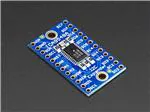
Adafruit TCA9548A 1-to-8 I2C Multiplexer
Breakout
Created by lady ada
https://learn.adafruit.com/adafruit-tca9548a-1-to-8-i2c-multiplexer-breakout
Last updated on 2022-10-19 09:17:49 AM EDT
©Adafruit Industries
Page 1 of 22
�Table of Contents
Overview
3
Pinouts
5
• Power Pins:
• I2C Control-Side pins:
• I2C Multiplexed-Side pins:
Assembly
6
• Prepare the header strip:
• Add the breakout board:
• And Solder!
Arduino Wiring & Test
9
• Example Multiplexing
• Multiple Multplexers
CircuitPython & Python
•
•
•
•
•
•
•
14
CircuitPython Microcontroller Wiring
Python Computer Wiring
Python Installation of TCA9548A Library
CircuitPython Usage
Python Usage
Simple Test Example Code
Multi-Sensor Example Code
Downloads
20
• Datasheets
• Schematic
• Fabrication Print
©Adafruit Industries
Page 2 of 22
�Overview
You just found the perfect I2C sensor, and you want to wire up two or three or more of
them to your Arduino when you realize "Uh oh, this chip has a fixed I2C address, and
from what I know about I2C, you cannot have two devices with the same address on
the same SDA/SCL pins!" Are you out of luck? You would be, if you didn't have this
ultra-cool TCA9548A 1-to-8 I2C multiplexer!
©Adafruit Industries
Page 3 of 22
�Finally, a way to get up to 8 same-address I2C devices hooked up to one
microcontroller - this multiplexer acts as a gatekeeper, shuttling the commands to the
selected set of I2C pins with your command.
Using it is fairly straight-forward: the multiplexer itself is on I2C address 0x70 (but can
be adjusted from 0x70 to 0x77) and you simply write a single byte with the desired
multiplexed output number to that port, and bam - any future I2C packets will get sent
to that port. In theory, you could have 8 of these multiplexers on each of 0x70-0x77
addresses in order to control 64 of the same-I2C-addressed-part.
©Adafruit Industries
Page 4 of 22
�Like all Adafruit breakouts, we put this nice chip on a breakout for you so you can use
it on a breadboard with capacitors, and pullups and pulldowns to make usage a snap.
Some header is required and once soldered in you can plug it into a solderlessbreadboard. The chip itself is 1.8V - 5V compliant so you can use it with any logic
level.
We even wrote up a nice tutorial with wiring diagrams, schematics and examples to
get you running in 10 minutes! (https://adafru.it/jhC)
Pinouts
Power Pins:
• Vin - this is the power pin. Since the sensor chip uses 3-5 VDC. To power the
board, give it the same power as the logic level of your microcontroller - e.g. for
a 5V micro like Arduino, use 5V
• GND - common ground for power and logic
I2C Control-Side pins:
• SCL - this is the I2C clock pin for the chip itself, connect to your microcontrollers
I2C clock line.
• SDA - this is the I2C data pin for the chip itself, connect to your microcontrollers
I2C data line.
©Adafruit Industries
Page 5 of 22
�• RST - this is the reset pin, for resetting the multiplexer chip. Pulled high by
default, connect to ground to reset
• A0 A1 A2 - these are the address selection pins for the multiplexer. By default
the multiplexer is at address 0x70 and these three pins are pulled low. Connect
them to Vin to set the address to 0x71 - 0x77.
• A0 is the lowest-significant bit (if it is pulled high, it will increase the address by
1).
• A1 is the 2nd-lowest-significant bit (if it is pulled high, it will increase the address
by 2).
• A2 is the 3rd-lowest-significant bit (if it is pulled high, it will increase the address
by 4).
I2C Multiplexed-Side pins:
• SDx and SCx: There are 8 sets of SDx and SCx pins, from SD0/SC0 to SD7/SC7.
These are the multiplexed pins. Each one is a completely seperate I2C bus set.
So you can have 8 I2C devices with identical addresses, as long as they are on
one I2C bus each.
These pins do not have any pullups installed, so if you are using a chip or
breakout without i2c pullups be sure to add them! Nicely, you can have Vin be
3.3V and have these pins pulled up to 5V (that is, they are 5V compliant)
Assembly
©Adafruit Industries
Page 6 of 22
�Prepare the header strip:
Cut the strip to length if necessary. It will
be easier to solder if you insert it into a
breadboard - long pins down
Add the breakout board:
Place the breakout board over the pins so
that the short pins poke through the
breakout pads
©Adafruit Industries
Page 7 of 22
�And Solder!
Be sure to solder all pins for reliable
electrical contact.
(For tips on soldering, be sure to check out
our Guide to Excellent Soldering (https://
adafru.it/aTk)).
©Adafruit Industries
Page 8 of 22
�You're done! Check your solder joints
visually and continue onto the next steps
Arduino Wiring & Test
The TCA9548A multiplexer is interesting in that it has an I2C address (0x70 by
default) - and you basically send it a command to tell it which I2C multiplexed output
you want to talk to, then you can address the board you want to address.
We suggest using this little helper to help you select the port
©Adafruit Industries
Page 9 of 22
�#define TCAADDR 0x70
void tcaselect(uint8_t i) {
if (i > 7) return;
Wire.beginTransmission(TCAADDR);
Wire.write(1 << i);
Wire.endTransmission();
}
You can then call tcaselect(0) thru tcaselect(7) to set up the multiplexer.
Note that you if you happen to have I2C devices with I2C address 0x70, you will need
to short one of the Addr pins on the TCA9548 breakout to Vin in order to make it not
conflict. Given that you can have 0x70 thru 0x77, just find one that's free and you're
good to go!
Example Multiplexing
For example, say we want to talk to two HMC5883 breakouts. These magnetometers
have a fixed address of 0x1E so you cannot have two on one I2C bus. Wire up the
TCA9548 breakout so that:
• Vin is connected to 5V (on a 3V logic Arduino/microcontroller, use 3.3V)
• GND to ground
• SCL to I2C clock
• SDA to I2C data
Then wire up each of the other sensor breakouts to Vin, Ground and use one of the S
Cn / SDn multiplexed buses:
©Adafruit Industries
Page 10 of 22
�On an Arduino, which is what we're using, we suggest running this handy scanner
script which will tell you what the breakout detected
/**
* TCA9548 I2CScanner.ino -- I2C bus scanner for Arduino
*
* Based on https://playground.arduino.cc/Main/I2cScanner/
*
*/
#include "Wire.h"
#define TCAADDR 0x70
void tcaselect(uint8_t i) {
if (i > 7) return;
Wire.beginTransmission(TCAADDR);
Wire.write(1 << i);
Wire.endTransmission();
}
// standard Arduino setup()
void setup()
{
while (!Serial);
delay(1000);
Wire.begin();
Serial.begin(115200);
Serial.println("\nTCAScanner ready!");
for (uint8_t t=0; t<8; t++) {
tcaselect(t);
Serial.print("TCA Port #"); Serial.println(t);
for (uint8_t addr = 0; addr<=127; addr++) {
if (addr == TCAADDR) continue;
©Adafruit Industries
Page 11 of 22
�Wire.beginTransmission(addr);
if (!Wire.endTransmission()) {
Serial.print("Found I2C 0x");
}
Serial.println(addr,HEX);
}
}
Serial.println("\ndone");
}
void loop()
{
}
For example, running it on the above setup will give you:
Next up you will have to adjust whatever code you have to select the correct
multiplexed port!
Make sure before you query from the sensor that you call tcaselect to get the right
one
#include <Wire.h>
#include <Adafruit_Sensor.h>
#include <Adafruit_HMC5883_U.h>
#define TCAADDR 0x70
/* Assign a unique ID to this sensor at the same time */
Adafruit_HMC5883_Unified mag1 = Adafruit_HMC5883_Unified(1);
Adafruit_HMC5883_Unified mag2 = Adafruit_HMC5883_Unified(2);
void displaySensorDetails(Adafruit_HMC5883_Unified *mag)
{
sensor_t sensor;
mag->getSensor(&sensor);
©Adafruit Industries
Page 12 of 22
�Serial.println("------------------------------------");
Serial.print ("Sensor:
"); Serial.println(sensor.name);
Serial.print ("Driver Ver:
"); Serial.println(sensor.version);
Serial.print ("Unique ID:
"); Serial.println(sensor.sensor_id);
Serial.print ("Max Value:
"); Serial.print(sensor.max_value);
Serial.println(" uT");
Serial.print ("Min Value:
"); Serial.print(sensor.min_value);
Serial.println(" uT");
Serial.print ("Resolution:
"); Serial.print(sensor.resolution);
Serial.println(" uT");
Serial.println("------------------------------------");
Serial.println("");
delay(500);
}
void tcaselect(uint8_t i) {
if (i > 7) return;
Wire.beginTransmission(TCAADDR);
Wire.write(1 << i);
Wire.endTransmission();
}
void setup(void)
{
Serial.begin(9600);
Serial.println("HMC5883 Magnetometer Test"); Serial.println("");
/* Initialise the 1st sensor */
tcaselect(2);
if(!mag1.begin())
{
/* There was a problem detecting the HMC5883 ... check your connections */
Serial.println("Ooops, no HMC5883 detected ... Check your wiring!");
while(1);
}
/* Initialise the 2nd sensor */
tcaselect(6);
if(!mag2.begin())
{
/* There was a problem detecting the HMC5883 ... check your connections */
Serial.println("Ooops, no HMC5883 detected ... Check your wiring!");
while(1);
}
/* Display some basic information on this sensor */
tcaselect(2);
displaySensorDetails(&mag1);
tcaselect(6);
displaySensorDetails(&mag2);
}
void loop(void)
{
/* Get a new sensor event */
sensors_event_t event;
tcaselect(2);
mag1.getEvent(&event);
/* Display the results (magnetic vector values are in micro-Tesla (uT)) */
Serial.print("Sensor #1 - ");
Serial.print("X: "); Serial.print(event.magnetic.x); Serial.print(" ");
Serial.print("Y: "); Serial.print(event.magnetic.y); Serial.print(" ");
Serial.print("Z: "); Serial.print(event.magnetic.z); Serial.print("
");Serial.println("uT");
©Adafruit Industries
Page 13 of 22
�tcaselect(6);
mag2.getEvent(&event);
/* Display the results (magnetic vector values are in micro-Tesla (uT)) */
Serial.print("Sensor #2 - ");
Serial.print("X: "); Serial.print(event.magnetic.x); Serial.print(" ");
Serial.print("Y: "); Serial.print(event.magnetic.y); Serial.print(" ");
Serial.print("Z: "); Serial.print(event.magnetic.z); Serial.print("
");Serial.println("uT");
delay(500);
}
However, once you add all the tcaselect()'s you will be able to talk to both sensors!
Multiple Multplexers
Since the TCA9548 is addressible, you can have more than one multiplexer on the
bus. With 8 possible adresses, that means you can control as many as 64 separate
i2c buses.
To avoid conflict between devices with the same address on different multiplexers,
you can disable all channels on a multiplexer with the following code:
Wire.beginTransmission(TCAADDR1);
Wire.write(0); // no channel selected
Wire.endTransmission();
CircuitPython & Python
It's easy to use the TCA9548A with Python or CircuitPython, and the Adafruit_CircuitP
ython_TCA9548A (https://adafru.it/ZYD) module. This module allows you to easily
write Python code that allows you to multiplex up to 8 STEMMA boards with the TCA9
548A I2C multiplexer. You can use this multiplexer with any CircuitPython
microcontroller board or with a computer that has GPIO and Python thanks to
Adafruit_Blinka, our CircuitPython-for-Python compatibility library (https://adafru.it/
BSN).
If you're curious why you'd need an I2C multiplexer, be sure to check out this guide (h
ttps://adafru.it/-af) that goes in depth on working with multiple copies of the same I2C
device, which most likely have the same I2C address.
Working with Multiple Same Address
I2C Devices Learn Guide
https://adafru.it/-af
©Adafruit Industries
Page 14 of 22
�CircuitPython Microcontroller Wiring
First, wire up a TCA9548A to your board exactly as shown below. Here's an example
of wiring a Feather M4 to the TCA9548A with I2C using one of the handy STEMMA
QT (https://adafru.it/Ft4) connectors. Then, plug two TSL2591 STEMMA boards into
the TCA9548A via STEMMA plug 0 and STEMMA plug 1:
Board 3V to mux VIN (red wire)
Board GND to mux GND (black wire)
Board SCL to mux SCL (yellow wire)
Board SDA to mux SDA (blue wire)
TSL2591 1 SDA to mux SD0
TSL2591 1 SCL to mux SC0
TSL2591 1 VIN to mux VIN
TSL2591 1 GND to mux GND
TSL2591 2 SDA to mux SD1
TSL2591 2 SDA to mux SC1
TSL2591 2 VIN to mux VIN
TSL2591 2 GND to mux GND
You can also use standard 0.100" pitch headers to wire it up on a breadboard:
Board 3V to mux VIN (red wire)
Board GND to mux GND (black wire)
Board SCL to mux SCL (yellow wire)
Board SDA to mux SDA (blue wire)
TSL2591 1 SDA to mux SD0
TSL2591 1 SCL to mux SC0
TSL2591 1 VIN to mux VIN
TSL2591 1 GND to mux GND
TSL2591 2 SDA to mux SD1
TSL2591 2 SDA to mux SC1
TSL2591 2 VIN to mux VIN
TSL2591 2 GND to mux GND
©Adafruit Industries
Page 15 of 22
�Python Computer Wiring
Since there's dozens of Linux computers/boards you can use, below shows wiring for
Raspberry Pi. For other platforms, please visit the guide for CircuitPython on Linux to
see whether your platform is supported (https://adafru.it/BSN).
Here's the Raspberry Pi wired to the I2C multiplexer using I2C and a STEMMA QT (htt
ps://adafru.it/Ft4) connector:
Pi 3V to mux VIN (red wire)
Pi GND to mux GND (black wire)
Pi SCL to mux SCL (yellow wire)
Pi SDA to mux SDA (blue wire)
TSL2591 1 SDA to mux SD0
TSL2591 1 SCL to mux SC0
TSL2591 1 VIN to mux VIN
TSL2591 1 GND to mux GND
TSL2591 2 SDA to mux SD1
TSL2591 2 SDA to mux SC1
TSL2591 2 VIN to mux VIN
TSL2591 2 GND to mux GND
Finally here is an example of how to wire up a Raspberry Pi to the I2C multiplexer
using a solderless breadboard:
Pi 3V to mux VIN (red wire)
Pi GND to mux GND (black wire)
Pi SCL to mux SCL (yellow wire)
Pi SDA to mux SDA (blue wire)
TSL2591 1 SDA to mux SD0
TSL2591 1 SCL to mux SC0
TSL2591 1 VIN to mux VIN
TSL2591 1 GND to mux GND
TSL2591 2 SDA to mux SD1
TSL2591 2 SDA to mux SC1
TSL2591 2 VIN to mux VIN
TSL2591 2 GND to mux GND
©Adafruit Industries
Page 16 of 22
�Python Installation of TCA9548A Library
You'll need to install the Adafruit_Blinka library that provides the CircuitPython
support in Python. This may also require enabling I2C on your platform and verifying
you are running Python 3. Since each platform is a little different, and Linux changes
often, please visit the CircuitPython on Linux guide to get your computer ready (https:
//adafru.it/BSN)!
Once that's done, from your command line run the following command:
• sudo pip3 install adafruit-circuitpython-tca9548a
If your default Python is version 3, you may need to run pip instead. Make sure you
aren't trying to use CircuitPython on Python 2.x, it isn't supported!
CircuitPython Usage
To use with CircuitPython, you need to first install the TCA9548A library, and its
dependencies, into the lib folder on your CIRCUITPY drive. Then you need to
update code.py with the example script.
Thankfully, we can do this in one go. In the example below, click the Download
Project Bundle button below to download the necessary libraries and the code.py file
in a zip file. Extract the contents of the zip file, and copy the entire lib folder and the c
ode.py file to your CIRCUITPY drive.
Your CIRCUITPY/lib folder should contain the following folders and file:
• adafruit_bus_device/
• adafruit_tca9548a.mpy
• adafruit_tsl2591.mpy
©Adafruit Industries
Page 17 of 22
�Python Usage
Once you have the library pip3 installed on your computer, copy or download the
following example to your computer, and run the following, replacing code.py with
whatever you named the file:
python3 code.py
Simple Test Example Code
# SPDX-FileCopyrightText: 2021 Carter Nelson for Adafruit Industries
# SPDX-License-Identifier: MIT
# This example shows using TCA9548A to perform a simple scan for connected devices
import board
import adafruit_tca9548a
# Create I2C bus as normal
i2c = board.I2C() # uses board.SCL and board.SDA
# Create the TCA9548A object and give it the I2C bus
tca = adafruit_tca9548a.TCA9548A(i2c)
for channel in range(8):
if tca[channel].try_lock():
print("Channel {}:".format(channel), end="")
addresses = tca[channel].scan()
print([hex(address) for address in addresses if address != 0x70])
tca[channel].unlock()
If running CircuitPython: Once everything is saved to the CIRCUITPY drive, connect to
the serial console (https://adafru.it/Bec) to see the data printed out!
If running Python: The console output will appear wherever you are running Python.
©Adafruit Industries
Page 18 of 22
�In this simple test for the TCA9548A, an I2C scan is performed for all eight of its ports.
If any devices are connected, then the I2C address will be printed to the REPL next to
the channel number. If no device is connected, then the port will print with empty
brackets ( [] ).
Multi-Sensor Example Code
# SPDX-FileCopyrightText: 2021 ladyada for Adafruit Industries
# SPDX-License-Identifier: MIT
# This example shows using two TSL2491 light sensors attached to TCA9548A channels
0 and 1.
# Use with other I2C sensors would be similar.
import time
import board
import adafruit_tsl2591
import adafruit_tca9548a
# Create I2C bus as normal
i2c = board.I2C() # uses board.SCL and board.SDA
# Create the TCA9548A object and give it the I2C bus
tca = adafruit_tca9548a.TCA9548A(i2c)
# For each sensor, create it using the TCA9548A channel instead of the I2C object
tsl1 = adafruit_tsl2591.TSL2591(tca[0])
tsl2 = adafruit_tsl2591.TSL2591(tca[1])
# After initial setup, can just use sensors as normal.
while True:
print(tsl1.lux, tsl2.lux)
time.sleep(0.1)
In the multi-sensor example, the TCA9548A is used as an I2C multiplexer with two
TSL2591 light sensors. When the connected sensors are instantiated over I2C, the I2C
pins declared are the ports from 0 and 1 on the TCA9548A.
In the example, the first TSL2591 light sensor, instantiated as tsl1 , is plugged into
port 0 ( tca[0] ) and the second TSL2591 light sensor, instantiated as tsl2 , is
plugged into port 1 ( tca[1] ).
©Adafruit Industries
Page 19 of 22
�# Create the TCA9548A object and give it the I2C bus
tca = adafruit_tca9548a.TCA9548A(i2c)
# For each sensor, create it using the TCA9548A channel instead of the I2C object
tsl1 = adafruit_tsl2591.TSL2591(tca[0])
tsl2 = adafruit_tsl2591.TSL2591(tca[1])
In the loop, the readings from the two light sensors are printed to the REPL every
0.1 seconds.
while True:
print(tsl1.lux, tsl2.lux)
time.sleep(0.1)
Downloads
Datasheets
• TCA9548A datasheet (https://adafru.it/id8)
• Fritzing object in the Adafruit Fritzing Library (https://adafru.it/aP3)
• EagleCAD PCB files on GitHub (https://adafru.it/rzF)
Schematic
Click to embiggen
©Adafruit Industries
Page 20 of 22
�Fabrication Print
Dimensions in Inches
©Adafruit Industries
Page 21 of 22
�©Adafruit Industries
Page 22 of 22
�