TPS743xx
TP
S7
43x
x
TP
S7
43
xx
www.ti.com
SBVS065K – DECEMBER 2005 – REVISED AUGUST 2010
1.5A Ultra-LDO with Programmable Sequencing
Check for Samples: TPS743xx
FEATURES
1
•
2
•
•
•
•
•
•
•
•
•
•
Track Pin Allows for Flexible Power-Up
Sequencing
1% Accuracy Over Line, Load, and
Temperature
Supports Input Voltages as Low as 0.9V with
External Bias Supply
Adjustable Output (0.8V to 3.6V)
Fixed Output (0.9V to 3.6V)
Ultra-Low Dropout: 55mV at 1.5A (typ)
Stable with Any or No Output Capacitor
Excellent Transient Response
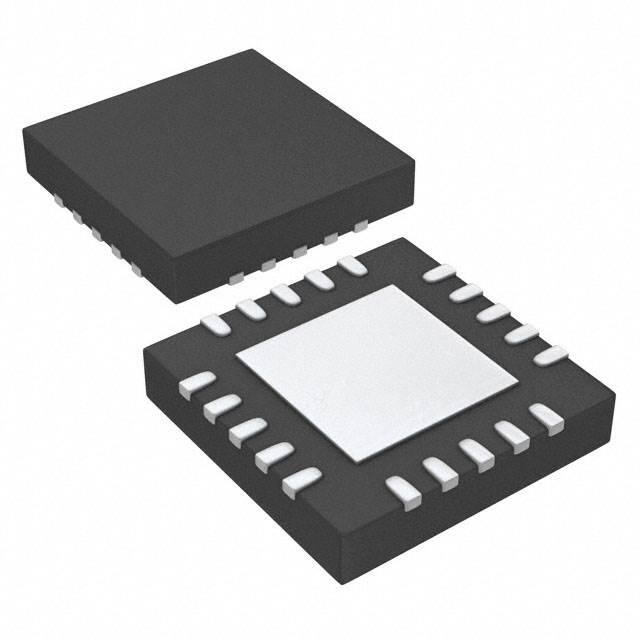
Available in 5mm × 5mm × 1mm QFN and
DDPAK-7 Packages
Open-Drain Power-Good (5 × 5 QFN)
Active High Enable
APPLICATIONS
•
•
•
•
FPGA Applications
DSP Core and I/O Voltages
Post-Regulation Applications
Applications with Special Start-Up Time or
Sequencing Requirements
DESCRIPTION
The TPS743xx low-dropout (LDO) linear regulators
provide an easy-to-use robust power management
solution for a wide variety of applications. The
TRACK pin allows the output to track an external
supply. This feature is useful in minimizing the stress
on ESD structures that are present between the
CORE and I/O power pins of many processors. The
enable input and power-good output allow easy
sequencing with external regulators. This complete
flexibility allows the user to configure a solution that
meets the sequencing requirements of FPGAs,
DSPs, and other applications with special start-up
requirements.
A precision reference and error amplifier deliver 1%
accuracy over load, line, temperature, and process.
Each LDO is stable with low-cost ceramic output
capacitors and the family is fully specified from –40°C
to +125°C. The TPS743xx is offered in a small (5mm
× 5mm) QFN package, yielding a highly compact total
solution size. For applications that require additional
power dissipation, the DDPAK (KTW) package is also
available.
ADJUSTABLE VOLTAGE VERSION
VIN
CIN
IN
BIAS
R1
VTRACK
500mV/div
FB
TRACK
R3
VTRACK
VPG
VOUT
OUT
CBIAS
IOUT = 500mA
R5
EN
VBIAS
VPG
PG
TPS74301
GND
COUT
R2
Optional
R4
FIXED VOLTAGE VERSION
VIN
CIN
IN
VOUT
VOUT
OUT
CBIAS
BIAS
VTRACK
R3
Time (20ms/div)
Figure 1. Tracking Response
R5
EN
VBIAS
VPG
PG
TPS743xx
R4
SNS
TRACK
COUT
GND
Optional
Figure 2. Typical Application Circuit
1
2
Please be aware that an important notice concerning availability, standard warranty, and use in critical applications of Texas
Instruments semiconductor products and disclaimers thereto appears at the end of this data sheet.
All trademarks are the property of their respective owners.
PRODUCTION DATA information is current as of publication date.
Products conform to specifications per the terms of the Texas
Instruments standard warranty. Production processing does not
necessarily include testing of all parameters.
Copyright © 2005–2010, Texas Instruments Incorporated
�TPS743xx
SBVS065K – DECEMBER 2005 – REVISED AUGUST 2010
www.ti.com
This integrated circuit can be damaged by ESD. Texas Instruments recommends that all integrated circuits be handled with
appropriate precautions. Failure to observe proper handling and installation procedures can cause damage.
ESD damage can range from subtle performance degradation to complete device failure. Precision integrated circuits may be more
susceptible to damage because very small parametric changes could cause the device not to meet its published specifications.
ORDERING INFORMATION (1)
PRODUCT
TPS743xx yyy z
(1)
(2)
(3)
VOUT
(2)
XX is nominal output voltage (for example, 12 = 1.2V, 15 = 1.5V, 01 = Adjustable). (3)
YYY is package designator.
Z is package quantity.
For the most current package and ordering information see the Package Option Addendum at the end of this document, or see the TI
website at www.ti.com.
Output voltages from 0.9V to 1.5V in 50mV increments and 1.5V to 3.3V in 100mV increments are available through the use of
innovative factory EEPROM programming; minimum order quantities may apply. Contact factory for details and availability.
For fixed 0.8V operation, tie FB to OUT.
ABSOLUTE MAXIMUM RATINGS (1)
At TJ = –40°C to +125°C, unless otherwise noted. All voltages are with respect to GND.
VIN, VBIAS Input voltage range
–0.3 to +6
V
–0.3 to +6
V
VPG Power-good voltage range
–0.3 to +6
V
IPG PG sink current
VFB Feedback pin voltage range
VOUT Output voltage range
IOUT Maximum output current
0 to +1.5
mA
–0.3 to +6
V
–0.3 to +6
V
–0.3 to VIN + 0.3
V
Internally limited
Output short circuit duration
Indefinite
PDISS Continuous total power dissipation
See Thermal Information Table
TJ Operating junction temperature range
TSTG Storage junction temperature range
2
UNIT
VEN Enable voltage range
VTRACK Track pin voltage range
(1)
TPS743xx
–40 to +125
°C
–55 to +150
°C
Stresses beyond those listed under Absolute Maximum Ratings may cause permanent damage to the device. These are stress ratings
only and functional operation of the device at these conditions is not implied. Exposure to absolute-maximum-rated conditions for
extended periods may affect device reliability.
Submit Documentation Feedback
Copyright © 2005–2010, Texas Instruments Incorporated
�TPS743xx
www.ti.com
SBVS065K – DECEMBER 2005 – REVISED AUGUST 2010
THERMAL INFORMATION
TPS743xx (2)
THERMAL METRIC (1)
RGW (20 PINS)
KTW (7 PINS)
qJA
Junction-to-ambient thermal resistance (3)
30.5
20.1
qJCtop
Junction-to-case (top) thermal resistance (4)
27.6
2.1
(5)
qJB
Junction-to-board thermal resistance
yJT
Junction-to-top characterization parameter (6)
yJB
Junction-to-board characterization parameter (7)
qJCbot
(1)
(2)
(3)
(4)
(5)
(6)
(7)
(8)
Junction-to-case (bottom) thermal resistance
(8)
N/A
N/A
0.37
4.2
10.6
6.1
4.1
1.4
UNITS
°C/W
For more information about traditional and new thermal metrics, see the IC Package Thermal Metrics application report, SPRA953A.
Thermal data for the RGW and KTW packages are derived by thermal simulations based on JEDEC-standard methodology as specified
in the JESD51 series. The following assumptions are used in the simulations:
(a) i. RGW: The exposed pad is connected to the PCB ground layer through a 4x4 thermal via array.
- ii. KTW: The exposed pad is connected to the PCB ground layer through a 6x6 thermal via array.
(b) Each of top and bottom copper layers has a dedicated pattern for 20% copper coverage.
(c) These data were generated with only a single device at the center of a JEDEC high-K (2s2p) board with 3in × 3in copper area. To
understand the effects of the copper area on thermal performance, refer to the Power Dissipation and Estimating Junction
Temperature sections.
The junction-to-ambient thermal resistance under natural convection is obtained in a simulation on a JEDEC-standard, high-K board, as
specified in JESD51-7, in an environment described in JESD51-2a.
The junction-to-case (top) thermal resistance is obtained by simulating a cold plate test on the top of the package. No specific
JEDEC-standard test exists, but a close description can be found in the ANSI SEMI standard G30-88.
The junction-to-board thermal resistance is obtained by simulating in an environment with a ring cold plate fixture to control the PCB
temperature, as described in JESD51-8.
The junction-to-top characterization parameter, yJT, estimates the junction temperature of a device in a real system and is extracted
from the simulation data to obtain qJA using a procedure described in JESD51-2a (sections 6 and 7).
The junction-to-board characterization parameter, yJB, estimates the junction temperature of a device in a real system and is extracted
from the simulation data to obtain qJA using a procedure described in JESD51-2a (sections 6 and 7).
The junction-to-case (bottom) thermal resistance is obtained by simulating a cold plate test on the exposed (power) pad. No specific
JEDEC standard test exists, but a close description can be found in the ANSI SEMI standard G30-88.
Copyright © 2005–2010, Texas Instruments Incorporated
Submit Documentation Feedback
3
�TPS743xx
SBVS065K – DECEMBER 2005 – REVISED AUGUST 2010
www.ti.com
ELECTRICAL CHARACTERISTICS
At VEN = 1.1V, VIN = VOUT + 0.3V, CIN = CBIAS = 0.1mF, COUT = 10mF, IOUT = 50mA, VBIAS = 5.0V, and TJ = –40°C to +125°C,
unless otherwise noted. Typical values are at TJ = +25°C.
TPS743xx
PARAMETER
MAX
UNIT
VIN Input voltage range
VOUT + VDO
5.5
V
VBIAS Bias pin voltage range
2.375
5.25
V
0.804
V
3.6
V
±0.2
1
%
VREF Internal reference (Adj.)
Output voltage range
VOUT
Accuracy
(1)
VOUT/VIN Line regulation
VOUT/IOUT Load regulation
VDO
VIN dropout voltage (2)
VBIAS dropout voltage (2)
ICL Current limit
IBIAS Bias pin current
TEST CONDITIONS
MIN
TJ = +25°C
0.796
VIN = 5V, IOUT = 1.5A, VBIAS = 5V
VREF
2.375V ≤ VBIAS ≤ 5.25V, VOUT + 1.62V ≤ VBIAS
50mA ≤ IOUT ≤ 1.5A
–1
(NOM)
+ 0.3 ≤ VIN ≤ 5.5V, QFN
0.0005
0.05
VOUT
(NOM)
+ 0.3 ≤ VIN ≤ 5.5V, DDPAK
0.0005
0.06
0mA ≤ IOUT ≤ 50mA
0.013
50mA ≤ IOUT ≤ 1.5A
0.04
100
IOUT = 1.5A, VBIAS – VOUT (NOM) ≥ 1.62V, DDPAK
60
120
1.4
VOUT = 80% × VOUT (NOM)
1.8
IOUT = 0mA to 1.5A
IOUT = 50mA to 1.5A
–250
1
100
mA
68
250
nA
Power-supply rejection
(VBIAS to VOUT)
1kHz, IOUT = 1.5A, VIN = 1.8V, VOUT = 1.5V
67
800kHz, IOUT = 1.5A, VIN = 1.8V, VOUT = 1.5V
50
tSTR Minimum startup time
ITR Track pin current
IOUT = 50mA to 1.5A at 1A/ms, COUT = none
VTRACK > 0.8V
VTRACK = 0.4V
%VOUT
ms
60
mV
1
mA
5.5
V
0
0.4
50
VEN = 5V
VIT PG trip threshold
VOUT decreasing
86.5
VHYS PG trip hysteresis
ms
0.1
1
mA
90
93.5
%VOUT
3
VPG, LO PG output low voltage
IPG = 1mA (sinking), VOUT < VIT
IPG, LKG PG leakage current
VPG = 5.25V, VOUT > VIT
V
mV
20
IEN Enable pin current
Thermal shutdown
temperature
3.5
0.1
VEN, DG Enable pin deglitch time
TSD
mVRMS
1.1
VEN, HYS Enable pin hysteresis
Operating junction
temperature
dB
25 × VOUT
–60
VEN, LO Enable input low level
TJ
dB
40
0.2V ≤ VTRACK ≤ 0.7V, VOUT = 0.8V
VEN, HI Enable input high level
4
mA
42
TACC Track pin accuracy
(1)
(2)
(3)
A
4
73
100Hz to 100kHz, IOUT = 1.5A
V
2
800kHz, IOUT = 1.5A, VIN = 1.8V, VOUT = 1.5V
%VOUT droop during load
transient
mV
4
1kHz, IOUT = 1.5A, VIN = 1.8V, VOUT = 1.5V
Noise Output noise voltage
%/A
55
IOUT = 1.5A, VIN = VBIAS
%/V
%/mA
IOUT = 1.5A, VBIAS – VOUT (NOM) ≥ 1.62V, QFN
Power-supply rejection
(VIN to VOUT)
PSRR
VTRAN
0.8
VOUT
ISHDN Shutdown supply current (VIN) VEN ≤ 0.4V
IFB, ISNS Feedback, Sense pin
current (3)
TYP
0.3
–40
Shutdown, temperature increasing
+155
Reset, temperature decreasing
+140
%VOUT
0.3
V
1
mA
+125
°C
°C
Adjustable devices tested at 0.8V; external resistor tolerance is not taken into account.
Dropout is defined as the voltage from the input to VOUT when VOUT is 2% below nominal.
IFB, ISNS current flow is out of the device.
Submit Documentation Feedback
Copyright © 2005–2010, Texas Instruments Incorporated
�TPS743xx
www.ti.com
SBVS065K – DECEMBER 2005 – REVISED AUGUST 2010
BLOCK DIAGRAMS
IN
Current
Limit
BIAS
UVLO
VOUT
Thermal
Limit
VTRACK < VREF = 1, VTRACK > VREF = 0
R1
1
TRACK
0
VOUT = 0.8 x (1 +
0.8V
Reference
R1
)
R2
FB
PG
Hysteresis
and De-Glitch
EN
R2
0.9 ´ VREF
GND
Figure 3. Adjustable Voltage Version
IN
Current
Limit
BIAS
UVLO
OUT
RSMALL
SNS
VTRACK < VREF = 1, VTRACK > VREF = 0
Thermal
Limit
1
TRACK
VOUT
R1
0
0.8V
Reference
R2
PG
EN
Hysteresis
and De-Glitch
0.9 ´ VREF
GND
Figure 4. Fixed Voltage Versions
Copyright © 2005–2010, Texas Instruments Incorporated
Submit Documentation Feedback
5
�TPS743xx
SBVS065K – DECEMBER 2005 – REVISED AUGUST 2010
www.ti.com
Table 1. Standard 1% Resistor Values for Programming the Output Voltage (1)
(1)
6
R1 (kΩ)
R2 (kΩ)
VOUT (V)
Short
Open
0.8
0.619
4.99
0.9
1.13
4.53
1.0
1.37
4.42
1.05
1.87
4.99
1.1
2.49
4.99
1.2
4.12
4.75
1.5
3.57
2.87
1.8
3.57
1.69
2.5
3.57
1.15
3.3
VOUT = 0.8 × (1 + R1/R2)
Submit Documentation Feedback
Copyright © 2005–2010, Texas Instruments Incorporated
�TPS743xx
www.ti.com
SBVS065K – DECEMBER 2005 – REVISED AUGUST 2010
PIN CONFIGURATIONS
IN
NC
NC
NC
OUT
5
4
3
2
1
RGW PACKAGE
5 × 5 QFN-20
(TOP VIEW)
KTW PACKAGE
DDPAK-7
SURFACE-MOUNT
IN
6
20
OUT
IN
7
19
OUT
IN
8
18
OUT
PG
9
17
NC
BIAS
10
16
FB/SNS
11
12
13
14
15
EN
GND
NC
NC
SS
TPS743xx
GND
1 2 3 4 5 6 7
SS OUT IN EN
FB/ GND BIAS
SNS
PIN DESCRIPTIONS
NAME
KTW (DDPAK)
RGW (QFN)
IN
5
5–8
Unregulated input to the device.
EN
7
11
Enable pin. Driving this pin high enables the regulator. Driving this pin low puts
the regulator into shutdown mode. This pin must not be left floating.
TRACK
1
15
Tracking pin. Connect this pin to the center tap of a resistor divider off of an
external supply to program the device to track an external supply.
BIAS
6
10
Bias input voltage for error amplifier, reference, and internal control circuits.
9
Power-Good (PG) is an open-drain, active-high output that indicates the status
of VOUT. When VOUT exceeds the PG trip threshold, the PG pin goes into a
high-impedance state. When VOUT is below this threshold the pin is driven to a
low-impedance state. A pull-up resistor from 10kΩ to 1MΩ should be connected
from this pin to a supply up to 5.5V. The supply can be higher than the input
voltage. Alternatively, the PG pin can be left floating if output monitoring is not
necessary.
PG
N/A
FB
2
16
DESCRIPTION
This pin is the feedback connection to the center tap of an external resistor
divider network that sets the output voltage. This pin must not be left floating.
(Adjustable version only.)
This pin is the sense connection to the load device. This pin must be connected
to VOUT and must not be left floating. (Fixed versions only.)
SNS
OUT
3
1, 18–20
NC
N/A
2–4, 13, 14, 17
GND
4
12
PAD/TAB
Copyright © 2005–2010, Texas Instruments Incorporated
Regulated output voltage. No capacitor is required on this pin for stability.
No connection. This pin can be left floating or connected to GND to allow better
thermal contact to the top-side plane.
Ground
Should be soldered to the ground plane for increased thermal performance.
Submit Documentation Feedback
7
�TPS743xx
SBVS065K – DECEMBER 2005 – REVISED AUGUST 2010
www.ti.com
TYPICAL CHARACTERISTICS
At TJ = +25°C, VOUT = 1.5V, VIN = VOUT(TYP) + 0.3V, VBIAS = 3.3V, IOUT = 50mA, EN = VIN, CIN = 1mF, CBIAS = 4.7mF, and COUT = 10mF,
unless otherwise noted.
LOAD REGULATION
LOAD REGULATION
1.0
0.050
Referred to IOUT = 50mA
0.9
Referred to IOUT = 50mA
0.025
0.7
0.6
-40°C
0.5
0.4
+25°C
0.3
0
Change in VOUT (%)
Change in VOUT (%)
0.8
0.2
+25°C
-0.025
-0.050
-40°C
-0.075
+125°C
-0.100
0.1
+125°C
0
-0.125
-0.1
-0.150
0
10
20
30
40
50
50
500
1000
1500
IOUT (mA)
IOUT (mA)
Figure 5.
Figure 6.
LINE REGULATION
VIN DROPOUT VOLTAGE vs
IOUT AND TEMPERATURE (TJ)
0.05
100
0.04
0.02
Dropout Voltage (mV)
Change in VOUT (%)
0.03
TJ = -40°C
0.01
0
-0.01
TJ = +25°C
TJ = +125°C
-0.02
75
+125°C
50
+25°C
25
-40°C
-0.03
-0.04
0
-0.05
0
0.5
1.0
1.5
2.0
2.5
3.0
3.5
4.0
4.5
0
0.5
VIN - VOUT (V)
IOUT (A)
Figure 8.
VIN DROPOUT VOLTAGE vs
VBIAS – VOUT AND TEMPERATURE (TJ)
VIN DROPOUT VOLTAGE vs
VBIAS – VOUT AND TEMPERATURE (TJ)
60
IOUT = 1.5A
180
IOUT = 500mA
50
Dropout Voltage (mV)
160
Dropout Voltage (mV)
1.5
Figure 7.
200
140
120
+125°C
100
+25°C
80
60
40
40
+125°C
30
+25°C
20
10
-40°C
20
-40°C
0
0
0.9
8
1.0
1.4
1.9
2.4
2.9
3.4
3.9
0.9
1.4
1.9
2.4
2.9
VBIAS - VOUT (V)
VBIAS - VOUT (V)
Figure 9.
Figure 10.
Submit Documentation Feedback
3.4
3.9
Copyright © 2005–2010, Texas Instruments Incorporated
�TPS743xx
www.ti.com
SBVS065K – DECEMBER 2005 – REVISED AUGUST 2010
TYPICAL CHARACTERISTICS (continued)
At TJ = +25°C, VOUT = 1.5V, VIN = VOUT(TYP) + 0.3V, VBIAS = 3.3V, IOUT = 50mA, EN = VIN, CIN = 1mF, CBIAS = 4.7mF, and COUT =
10mF, unless otherwise noted.
VBIAS PSRR vs FREQUENCY
1400
90
1300
80
1200
+25°C
+125°C
1100
Power-Supply Rejection (dB)
Dropout Voltage (mV)
VBIAS DROPOUT VOLTAGE vs
IOUT AND TEMPERATURE
1000
-40°C
900
800
700
IOUT = 1.5A
70
60
50
40
30
20
10
600
0
500
50
500
1000
1500
10
100
1k
IOUT (mA)
COUT = 100mF C
OUT = 10mF
60
50
40
30
20
COUT = 0mF
10
Power-Supply Rejection Ratio (dB)
Power-Supply Rejection Ratio (dB)
VIN = 1.8, VOUT = 1.5V, IOUT = 100mA
70
VIN = 1.8, VOUT = 1.5V, IOUT = 1.5A
90
80
70
COUT = 100mF
60
COUT = 10mF
50
40
30
20
10
COUT = 0mF
0
0
10
100
1k
10k
100k
1M
10
10M
100
Figure 13.
Figure 14.
700kHz
60
50
300kHz
100kHz
20
10
IOUT = 1.5A
0
0.25 0.50 0.75 1.00 1.25 1.50 1.75 2.00 2.25 2.50
VIN - VOUT (V)
Figure 15.
Copyright © 2005–2010, Texas Instruments Incorporated
Output Spectral Noise Density (mV/ÖHz)
Power-Supply Rejection Ratio (dB)
1kHz
40
100k
1M
10M
NOISE SPECTRAL DENSITY
80
0
10k
Frequency (Hz)
VIN PSRR vs VIN – VOUT
30
1k
Frequency (Hz)
90
70
10M
VIN PSRR vs FREQUENCY
100
80
1M
Figure 12.
VIN PSRR vs FREQUENCY
90
100k
Frequency (Hz)
Figure 11.
100
10k
1
IOUT = 1.5A
VOUT = 1.1V
0.1
0.01
100
1k
10k
100k
Frequency (Hz)
Figure 16.
Submit Documentation Feedback
9
�TPS743xx
SBVS065K – DECEMBER 2005 – REVISED AUGUST 2010
www.ti.com
TYPICAL CHARACTERISTICS (continued)
At TJ = +25°C, VOUT = 1.5V, VIN = VOUT(TYP) + 0.3V, VBIAS = 3.3V, IOUT = 50mA, EN = VIN, CIN = 1mF, CBIAS = 4.7mF, and COUT =
10mF, unless otherwise noted.
IBIAS vs IOUT AND TEMPERATURE
IBIAS vs VBIAS AND VOUT
2.85
3.0
2.8
2.65
+125°C
2.25
2.05
+25°C
1.85
1.65
+125°C
2.6
Bias Current (mA)
Bias Current (mA)
2.45
-40°C
2.4
2.2
+25°C
2.0
1.8
1.6
-40°C
1.4
1.45
1.2
1.25
1.0
0
0.5
1.0
2.0
1.5
3.0
3.5
VBIAS (V)
Figure 17.
Figure 18.
IBIAS SHUTDOWN vs TEMPERATURE
4.0
4.5
5.0
LOW-LEVEL PG VOLTAGE vs PG CURRENT
1.0
0.40
VOL Low-Level PG Voltage (V)
0.45
VBIAS = 2.375V
0.35
Bias Current (mA)
2.5
IOUT (A)
0.30
VBIAS = 5.5V
0.25
0.20
0.15
0.10
0.05
0.9
0.8
0.7
0.6
0.5
0.4
0.3
0.2
0.1
0
0
-40
-20
0
20
40
60
80
100
120
0
2
6
4
Junction Temperature (°C)
8
10
12
PG Current (mA)
Figure 19.
Figure 20.
VBIAS LINE TRANSIENT
VIN LINE TRANSIENT (1.5A)
20mV/div
COUT = 2 x 470mF (OSCON)
20mV/div
COUT = 100mF (Cer.)
10mV/div
COUT = 2 x 470mF (OSCON)
VOUT = 1.2V
COUT = 100mF (Cer.)
10mV/div
10mV/div
COUT = 10mF (Cer.)
COUT = 10mF (Cer.)
20mV/div
COUT = 0mF
10mV/div
COUT = 0mF
20mV/div
2.5V
4.3V
4.3V
1V/div
1V/ms
1V/ms
3.3V
Time (50ms/div)
Figure 21.
10
Submit Documentation Feedback
500mV/div
1.5V
Time (50ms/div)
Figure 22.
Copyright © 2005–2010, Texas Instruments Incorporated
�TPS743xx
www.ti.com
SBVS065K – DECEMBER 2005 – REVISED AUGUST 2010
TYPICAL CHARACTERISTICS (continued)
At TJ = +25°C, VOUT = 1.5V, VIN = VOUT(TYP) + 0.3V, VBIAS = 3.3V, IOUT = 50mA, EN = VIN, CIN = 1mF, CBIAS = 4.7mF, and COUT =
10mF, unless otherwise noted.
OUTPUT LOAD TRANSIENT RESPONSE
TRACKING RESPONSE
COUT = 2 x 470mF (OSCON)
IOUT = 500mA
50mV/div
COUT = 100mF (Cer.)
50mV/div
VTRACK
50mV/div
500mV/div
VPG
COUT = 10mF (Cer.)
COUT = 0mF
50mV/div
VOUT
1.5A
1A/ms
1A/div
50mA
Time (50ms/div)
Time (20ms/div)
Figure 23.
Figure 24.
POWER-UP/POWER-DOWN
TURN-ON RESPONSE–QFN PACKAGE
VIN = VBIAS = VEN
VPG (500mV/div)
VTRACK = VIN
IOUT = 1.5A
VOUT
1V/div
1V/div
VOUT
1.1V
1V/div
0V
VEN
Time (50ms/div)
Time (20ms/div)
Figure 25.
Figure 26.
OUTPUT SHORT-CIRCUIT RECOVERY
IOUT
500mA/div
VOUT
50mV/div
Output Shorted
Output Open
Time (20ms/div)
Figure 27.
Copyright © 2005–2010, Texas Instruments Incorporated
Submit Documentation Feedback
11
�TPS743xx
SBVS065K – DECEMBER 2005 – REVISED AUGUST 2010
www.ti.com
APPLICATION INFORMATION
The TPS743xx belongs to a family of new generation
ultra-low dropout regulators that feature soft-start and
tracking capabilities. These regulators use a low
current bias input to power all internal control
circuitry, allowing the NMOS pass transistor to
regulate very low input and output voltages.
R1 and R2 can be calculated for any output voltage
using the formula shown in Figure 28. Refer to
Table 1 for sample resistor values of common output
voltages. In order to achieve the maximum accuracy
specifications, R2 should be ≤ 4.99kΩ.
The use of an NMOS-pass FET offers several critical
advantages for many applications. Unlike a PMOS
topology device, the output capacitor has little effect
on loop stability. This architecture allows the
TPS743xx to be stable with any or even no output
capacitor. Transient response is also superior to
PMOS topologies, particularly for low VIN
applications.
FIXED VOLTAGE AND SENSE PIN
The TPS743xx features a TRACK pin that allows the
output to track an external supply. This feature is
useful in minimizing the stress on ESD structures that
are present between the CORE and I/O power pins of
many processors. A power-good (PG) output is also
available to allow supply monitoring and sequencing
of follow-on supplies. To control the output turn-on,
an enable (EN) pin with hysteresis and deglitch is
provided to allow slow-ramping signals to be utilized
for sequencing the device. The low VIN and VOUT
capability allows for inexpensive, easy-to-design, and
efficient linear regulation between the multiple supply
voltages often present in processor intensive
systems.
ADJUSTABLE VOLTAGE PART AND
SETTING
Figure 28 is a typical application circuit for the
TPS74301 adjustable device.
Figure 29 illustrates a typical application circuit for the
TPS743xx fixed output device.
VIN
CIN
IN
R5
EN
VBIAS
VPG
PG
TPS743xx
VOUT
OUT
CBIAS
BIAS
VTRACK
R3
R4
SNS
TRACK
COUT
GND
Optional
Figure 29. Typical Application Circuit for the
TPS743xx (Fixed Voltage)
A fixed voltage version of the TPS743xx has a sense
pin (SNS) so that the device can monitor its output
voltage at the load device pin(s) as closely as
possible. Unlike other TI fixed-voltage LDOs,
however, this pin must not be left floating; it must be
connected to an output node. See the TI application
report, Ultimate Regulation of with Fixed Output
Versions of the TPS742xx, TPS743xx, and TPS744xx
(literature number SBVA024), available for download
from the TI web site.
INPUT, OUTPUT, AND BIAS CAPACITOR
REQUIREMENTS
VIN
CIN
IN
PG
TPS74301
R5
EN
VBIAS
VPG
VOUT
OUT
CBIAS
BIAS
R1
VTRACK
R3
FB
TRACK
COUT
Optional
GND
R2
R4
VOUT = 0.8 ´
(
1+
R1
R2
)
Figure 28. Typical Application Circuit for the
TPS74301 (Adjustable Version)
12
Submit Documentation Feedback
The device does not require any output capacitor for
stability. If an output capacitor is needed, the device
is designed to be stable for all available types and
values of output capacitance. The device is also
stable with multiple capacitors in parallel, of any type
or value.
The capacitance required on the IN and BIAS pins is
strongly dependent on the input supply source
impedance. To counteract any inductance in the
input, the minimum recommended capacitor for VIN
and VBIAS is 1mF. If VIN and VBIAS are connected to
the same supply, the recommended minimum
capacitor for VBIAS is 4.7mF. Good quality, low ESR
capacitors should be used on the input; ceramic X5R
and X7R capacitors are preferred. These capacitors
should be placed as close the pins as possible for
optimum performance.
Copyright © 2005–2010, Texas Instruments Incorporated
�TPS743xx
www.ti.com
SBVS065K – DECEMBER 2005 – REVISED AUGUST 2010
TRANSIENT RESPONSE
The TPS743xx was designed to have transient
response within 5% for most applications without any
output capacitor. In some cases, the transient
response may be limited by the transient response of
the input supply. This limitation is especially true in
applications where the difference between the input
and output is less than 300mV. In this case, adding
additional input capacitance improves the transient
response much more than just adding additional
output capacitance would do. With a solid input
supply, adding additional output capacitance reduces
undershoot and overshoot during a transient at the
expense of a slightly longer VOUT recovery time. Refer
to Figure 23 in the Typical Characteristics section.
Since the TPS743xx is stable without an output
capacitor, many applications may allow for little or no
capacitance at the LDO output. For these
applications, local bypass capacitance for the device
under power may be sufficient to meet the transient
requirements of the application. This design reduces
the total solution cost by avoiding the need to use
expensive high-value capacitors at the LDO output.
DROPOUT VOLTAGE
The TPS743xx offers industry-leading dropout
performance, making it well-suited for high-current
low VIN/low VOUT applications. The extremely low
dropout of the TPS743xx allows the device to be
used instead of a DC/DC converter and still achieve
good efficiencies. This efficiency allows users to
rethink the power architecture for their applications to
find the smallest, simplest, and lowest cost solution.
There are two different specifications for dropout
voltage with the TPS743xx. The first specification (as
shown in Figure 30) is referred to as VIN Dropout and
is for users wishing to apply an external bias voltage
to achieve low dropout. This specification assumes
that VBIAS is at least 1.62V above VOUT, which is the
case for VBIAS when powered by a 3.3V rail with 5%
tolerance and with VOUT = 1.5V. If VBIAS is higher than
3.3V × 0.95 or VOUT is less than 1.5V, VIN dropout is
less than specified.
IN
BIAS
Reference
VBIAS = 5V ± 5%
VIN = 1.8V
VOUT = 1.5V
IOUT = 1.5A
Efficiency = 83%
OUT
VOUT
FB
Simplified Block Diagram
Figure 30. Typical Application of the TPS743xx
Using an Auxiliary Bias Rail
The second specification (shown in Figure 31),
referred to as VBIAS Dropout, is for users who wish to
tie IN and BIAS together. This option allows the
device to be used in applications where an auxiliary
bias voltage is unavailable or low dropout is not
required. Dropout is limited by BIAS in these
applications because VBIAS provides the gate drive to
the pass FET, and therefore must be 1.4V above
VOUT. Because of this usage, IN and BIAS tied
together easily consume huge power. Pay attention
not to exceed the power rating of the IC package.
VIN
BIAS
Reference
IN
VBIAS = 3.3V ± 5%
VIN = 3.3V ± 5%
VOUT = 1.5V
IOUT = 1.5A
Efficiency = 45%
OUT
VOUT
FB
Simplified Block Diagram
Figure 31. Typical Application of the TPS743xx
Without an Auxiliary Bias
Copyright © 2005–2010, Texas Instruments Incorporated
Submit Documentation Feedback
13
�TPS743xx
SBVS065K – DECEMBER 2005 – REVISED AUGUST 2010
www.ti.com
PROGRAMMABLE SEQUENCING WITH
TRACK
The TPS743xx features a track pin that allows the
output to track an external supply at start-up. While
the TRACK input is below 0.8V, the error amplifier
regulates the FB pin to the TRACK input. Properly
choosing the resistor divider network (R1 and R2) as
shown in Figure 32 enables the regulator output to
track the external supply to obtain a simultaneous or
ratiometric start-up. Once the TRACK input reaches
0.8V, the error amplifier regulates the FB pin to the
0.8V internal reference. Further increases to the
TRACK input have no effect.
TPS74201 LDO1
IN
5V
R3
32.4kW
(1)
OUT
BIAS
PG
EN
SS
DSP
3.3V
I/O
R1
R4
10kW
R2
TPS74301 LDO2
OUT
IN
BIAS
EN
(1)
1.2V
CORE
PG
TRACK
SIMULTANEOUS SEQUENCING
I/O
CORE
R1 =
VCCCORE - 0.8
0.8
RATIOMETRIC SEQUENCING
VOUT
x R2
The maximum recommended value for R2 is 100kΩ.
Once R2 is selected, R1 is calculated using one of the
equations given in Figure 32.
SEQUENCING REQUIREMENTS
The device can have VIN, VBIAS, VEN, and VTRACK
sequenced in any order without causing damage to
the device. However, for the track function to work as
intended, certain sequencing rules must be applied.
VBIAS must be present and the device enabled before
the track signal starts to ramp. VIN should ramp up
faster than the external supply being tracked so that
the tracking signal will not drive the device into VIN
dropout as VOUT ramps up. The preferred method to
sequence the tracking device is to have VIN, VBIAS,
and VEN above the minimum required voltages before
enabling the master supply to initiate the startup
sequence. This method is illustrated in Figure 32.
Resistors R3 and R4 disable the master supply until
the input voltage is above 3.52V (typical).
If the TRACK pin is not needed it should be
connected to VIN. Configured in this way, the device
starts up typically within 40ms, which may result in
large inrush current that could cause the input supply
to droop. If soft-start is needed, consider the
TPS742xx or TPS744xx devices.
NOTE: When VBIAS and VEN are present and VIN is
not supplied, this device outputs approximately 50mA
of current from OUT. Although this condition will not
cause any damage to the device, the output current
may charge up the OUT node if total resistance
between OUT and GND (including external feedback
resistors) is greater than 10kΩ.
(2)
I/O
CORE
R1 =
VCCIO - 0.808
0.808
x R2
Time
NOTES: (1) Capacitors on IN, BIAS, and OUT along with the resistors
necessary to set the output voltage have been omitted for simplification.
(2) Lowest value for VCORE and highest value for R2 should be used
in this calculation. R1 must be the closest standard value below the
calculated value for proper ratiometric sequencing.
Figure 32. Various Sequencing Methods Using
the TRACK Pin
14
Submit Documentation Feedback
Copyright © 2005–2010, Texas Instruments Incorporated
�TPS743xx
www.ti.com
ENABLE/SHUTDOWN
The enable (EN) pin is active high and is compatible
with standard digital signaling levels. VEN below 0.4V
turns the regulator off, while VEN above 1.1V turns the
regulator on. Unlike many regulators, the enable
circuitry has hysteresis and deglitching for use with
relatively slow-ramping analog signals. This
configuration allows the TPS743xx to be enabled by
connecting the output of another supply to the EN
pin. The enable circuitry typically has 50mV of
hysteresis and a deglitch circuit to help avoid on-off
cycling because of small glitches in the VEN signal.
The enable threshold is typically 0.8V and varies with
temperature and process variations. Temperature
variation is approximately –1mV/°C; therefore,
process variation accounts for most of the variation in
the enable threshold. If precise turn-on timing is
required, a fast rise-time signal should be used to
enable the TPS743xx.
If not used, EN can be connected to either IN or
BIAS. If EN is connected to IN, it should be
connected as close as possible to the largest
capacitance on the input to prevent voltage droops on
that line from triggering the enable circuit.
POWER-GOOD (QFN Package Only)
The power-good (PG) pin is an open-drain output and
can be connected to any 5.5V or lower rail through an
external pull-up resistor. This pin requires at least
1.1V on VBIAS in order to have a valid output. The PG
output is high-impedance when VOUT is greater than
VIT + VHYS. If VOUT drops below VIT or if VBIAS drops
below 1.9V, the open-drain output turns on and pulls
the PG output low. The PG pin also asserts when the
device is disabled. The recommended operating
condition of PG pin sink current is up to 1mA, so the
pull-up resistor for PG should be in the range of 10kΩ
to 1MΩ. PG is only provided on the QFN package. If
output voltage monitoring is not needed, the PG pin
can be left floating.
INTERNAL CURRENT LIMIT
SBVS065K – DECEMBER 2005 – REVISED AUGUST 2010
current during a short-circuit fault. Recovery from a
short-circuit condition is well-controlled and results in
very little output overshoot when the load is removed.
See Figure 27 in the Typical Characteristics section
for output short-circuit recovery performance.
The internal current limit protection circuitry of the
TPS743xx is designed to protect against overload
conditions. It is not intended to allow operation above
the rated current of the device. Continuously running
the TPS743xx above the rated current degrades
device reliability.
THERMAL PROTECTION
Thermal protection disables the output when the
junction temperature rises to approximately +155°C,
allowing the device to cool. When the junction
temperature cools to approximately +140°C, the
output circuitry is enabled. Depending on power
dissipation, thermal resistance, and ambient
temperature the thermal protection circuit may cycle
on and off. This cycling limits the dissipation of the
regulator, protecting it from damage as a result of
overheating.
Activation of the thermal protection circuit indicates
excessive
power
dissipation
or
inadequate
heatsinking.
For
reliable
operation,
junction
temperature should be limited to +125°C maximum.
To estimate the margin of safety in a complete design
(including
heatsink),
increase
the
ambient
temperature until thermal protection is triggered; use
worst-case loads and signal conditions. For good
reliability, thermal protection should trigger at least
+30°C above the maximum expected ambient
condition of the application. This condition produces a
worst-case junction temperature of +125°C at the
highest
expected
ambient
temperature
and
worst-case load.
The internal protection circuitry of the TPS743xx is
designed to protect against overload conditions. It is
not intended to replace proper heatsinking.
Continuously running the TPS743xx into thermal
shutdown degrades device reliability.
The TPS743xx features a factory-trimmed, accurate
current limit that is flat over temperature and supply
voltage. The current limit allows the device to supply
surges of up to 1.8A and maintain regulation. The
current limit responds in about 10ms to reduce the
Copyright © 2005–2010, Texas Instruments Incorporated
Submit Documentation Feedback
15
�TPS743xx
SBVS065K – DECEMBER 2005 – REVISED AUGUST 2010
www.ti.com
An optimal layout can greatly improve transient
performance, PSRR, and noise. To minimize the
voltage droop on the input of the device during load
transients, the capacitance on IN and BIAS should be
connected as close as possible to the device. This
capacitance also minimizes the effects of parasitic
inductance and resistance of the input source and
can therefore improve stability. To achieve optimal
transient performance and accuracy, the top side of
R1 in Figure 28 should be connected as close as
possible to the load. If BIAS is connected to IN, it is
recommended to connect BIAS as close to the sense
point of the input supply as possible. This connection
minimizes the voltage droop on BIAS during transient
conditions and can improve the turn-on response.
Knowing the device power dissipation and proper
sizing of the thermal plane that is connected to the
tab or pad is critical to avoiding thermal shutdown
and ensuring reliable operation. Power dissipation of
the device depends on input voltage and load
conditions, and can be calculated using Equation 1:
P D + ǒVIN * VOUTǓ
I OUT
(1)
Power dissipation can be minimized and greater
efficiency can be achieved by using the lowest
possible input voltage necessary to achieve the
required output voltage regulation.
On the QFN (RGW) package, the primary conduction
path for heat is through the exposed pad to the
printed circuit board (PCB). The pad can be
connected to ground or be left floating; however, it
should be attached to an appropriate amount of
copper PCB area to ensure the device will not
overheat. On the DDPAK (KTW) package, the
primary conduction path for heat is through the tab to
the PCB. That tab should be connected to ground.
The maximum junction-to-ambient thermal resistance
depends on the maximum ambient temperature,
maximum device junction temperature, and power
dissipation of the device and can be calculated using
Equation 2:
()125OC * T A)
R qJA +
PD
(2)
white space
Knowing the maximum RqJA, the minimum amount of
PCB copper area needed for appropriate heatsinking
can be estimated using Figure 33.
120
100
80
qJA (°C/W)
LAYOUT RECOMMENDATIONS AND POWER
DISSIPATION
60
qJA (RGW)
40
20
qJA (KTW)
0
0
1
2
3
4
5
7
6
8
9
10
2
Board Copper Area (in )
Note:
qJA value at board size of 9in2 (that is, 3in ×
3in) is a JEDEC standard.
Figure 33. qJA vs Board Size
Figure 33 shows the variation of qJA as a function of
ground plane copper area in the board. It is intended
only as a guideline to demonstrate the effects of heat
spreading in the ground plane and should not be
used to estimate actual thermal performance in real
application environments.
NOTE: When the device is mounted on an
application PCB, it is strongly recommended to use
ΨJT and ΨJB, as explained in the Estimating Junction
Temperature section.
16
Submit Documentation Feedback
Copyright © 2005–2010, Texas Instruments Incorporated
�TPS743xx
www.ti.com
SBVS065K – DECEMBER 2005 – REVISED AUGUST 2010
ESTIMATING JUNCTION TEMPERATURE
Using the thermal metrics ΨJT and ΨJB, shown in the
Thermal Information table, the junction temperature
can be estimated with corresponding formulas (given
in Equation 3). For backwards compatibility, an older
qJC,Top parameter is listed as well.
YJT: TJ = TT + YJT · PD
YJB: TJ = TB + YJB · PD
(3)
Where PD is the power dissipation shown by
Equation 1, TT is the temperature at the center-top of
the IC package, and TB is the PCB temperature
measured 1mm away from the IC package on the
PCB surface (as Figure 34 shows).
NOTE: Both TT and TB can be measured on actual
application boards using a thermo-gun (an infrared
thermometer).
For more information about measuring TT and TB, see
the application note Using New Thermal Metrics
(SBVA025), available for download at www.ti.com.
(1)
TT on top of IC
TB on PCB
TT on top of IC
1mm
TB on PCB
surface
(2)
1mm
(a) Example RGW (QFN) Package Measurement
(1)
TT is measured at the center of both the X- and Y-dimensional axes.
(2)
TB is measured below the package lead on the PCB surface.
(b) Example KTW (DDPAK) Package Measurement
Figure 34. Measuring Points for TT and TB
Copyright © 2005–2010, Texas Instruments Incorporated
Submit Documentation Feedback
17
�TPS743xx
SBVS065K – DECEMBER 2005 – REVISED AUGUST 2010
Looking at Figure 35, the RGW package thermal
performance has negligible dependency on board
size. The KTW package, however, does have a
measurable dependency on board size. This
dependency exists because the package shape is not
point-symmetric to an IC center. In the KTW package,
for example (see Figure 34), silicon is not beneath
the measuring point of TT which is the center of the X
and Y dimension, so that ΨJT has a dependency.
Also, because of that non-point-symmetry, device
heat distribution on the PCB is not point-symmetric,
either, so that ΨJB has a dependency.
space
12
10
YJT and YJB (°C/W)
Compared with qJA, the thermal metrics ΨJT and ΨJB
are less independent of board size, but they do have
a small dependency. Figure 35 shows characteristic
performance of ΨJT and ΨJB versus board size.
www.ti.com
YJB (RGW)
8
YJB (KTW)
6
4
YJT (KTW)
2
YJT (RGW)
0
0
2
4
6
8
10
2
Board Copper Area (in )
Figure 35. ΨJT and ΨJB vs Board Size
For a more detailed discussion of why TI does not
recommend using qJC,Top to determine thermal
characteristics, refer to the application note Using
New Thermal Metrics (SBVA025), available for
download at www.ti.com. Also, refer to the application
note IC Package Thermal Metrics (SPRA953) (also
available on the TI web site) for further information.
18
Submit Documentation Feedback
Copyright © 2005–2010, Texas Instruments Incorporated
�TPS743xx
www.ti.com
SBVS065K – DECEMBER 2005 – REVISED AUGUST 2010
REVISION HISTORY
NOTE: Page numbers for previous revisions may differ from page numbers in the current version.
Changes from Revision J (December, 2009) to Revision K
Page
•
Replaced the Dissipation Ratings table with the Thermal Information table ........................................................................ 3
•
Revised Layout Recommendations and Power Dissipation section ................................................................................... 16
•
Revised Estimating Junction Temperature section ............................................................................................................. 17
Changes from Revision I (August, 2009) to Revision J
Page
•
Changed last sentence of Layout Recommendations and Power Dissipation section; added Figure 33 .......................... 16
•
Added Estimating Junction Temperature section ............................................................................................................... 17
•
Deleted (previously numbered) Figure 33 through Figure 37 ............................................................................................. 18
Copyright © 2005–2010, Texas Instruments Incorporated
Submit Documentation Feedback
19
�PACKAGE OPTION ADDENDUM
www.ti.com
13-Aug-2021
PACKAGING INFORMATION
Orderable Device
Status
(1)
Package Type Package Pins Package
Drawing
Qty
Eco Plan
(2)
Lead finish/
Ball material
MSL Peak Temp
Op Temp (°C)
Device Marking
(3)
(4/5)
(6)
TPS74301KTWR
ACTIVE
DDPAK/
TO-263
KTW
7
500
RoHS & Green
Call TI | SN
Level-3-245C-168 HR
-40 to 85
TPS74301
TPS74301RGWR
ACTIVE
VQFN
RGW
20
3000
RoHS & Green
NIPDAU
Level-2-260C-1 YEAR
-40 to 85
TPS
74301
TPS74301RGWRG4
ACTIVE
VQFN
RGW
20
3000
RoHS & Green
NIPDAU
Level-2-260C-1 YEAR
-40 to 85
TPS
74301
TPS74301RGWT
ACTIVE
VQFN
RGW
20
250
RoHS & Green
NIPDAU
Level-2-260C-1 YEAR
-40 to 85
TPS
74301
TPS74301RGWTG4
ACTIVE
VQFN
RGW
20
250
RoHS & Green
NIPDAU
Level-2-260C-1 YEAR
-40 to 85
TPS
74301
(1)
The marketing status values are defined as follows:
ACTIVE: Product device recommended for new designs.
LIFEBUY: TI has announced that the device will be discontinued, and a lifetime-buy period is in effect.
NRND: Not recommended for new designs. Device is in production to support existing customers, but TI does not recommend using this part in a new design.
PREVIEW: Device has been announced but is not in production. Samples may or may not be available.
OBSOLETE: TI has discontinued the production of the device.
(2)
RoHS: TI defines "RoHS" to mean semiconductor products that are compliant with the current EU RoHS requirements for all 10 RoHS substances, including the requirement that RoHS substance
do not exceed 0.1% by weight in homogeneous materials. Where designed to be soldered at high temperatures, "RoHS" products are suitable for use in specified lead-free processes. TI may
reference these types of products as "Pb-Free".
RoHS Exempt: TI defines "RoHS Exempt" to mean products that contain lead but are compliant with EU RoHS pursuant to a specific EU RoHS exemption.
Green: TI defines "Green" to mean the content of Chlorine (Cl) and Bromine (Br) based flame retardants meet JS709B low halogen requirements of


 工商网监
湘ICP备2023018690号
工商网监
湘ICP备2023018690号
