LMBR120FT1G thru LMBR1200FT1G
Schottky Barrier Rectifiers
Reverse Voltage 20 to 200V Forward Current 1.0A
FEATURES
* Plastic package has Underwriters Laboratory
Flammability Classification 94V-0
* Low power loss,high efficiency
* For use in low voltage high frequency inverters,
free wheeling,and polarity protection applications
* Guardring for over voltage protection
* High temperature soldering guaranteed:
260°C/10 seconds at terminals
Mechanical Data
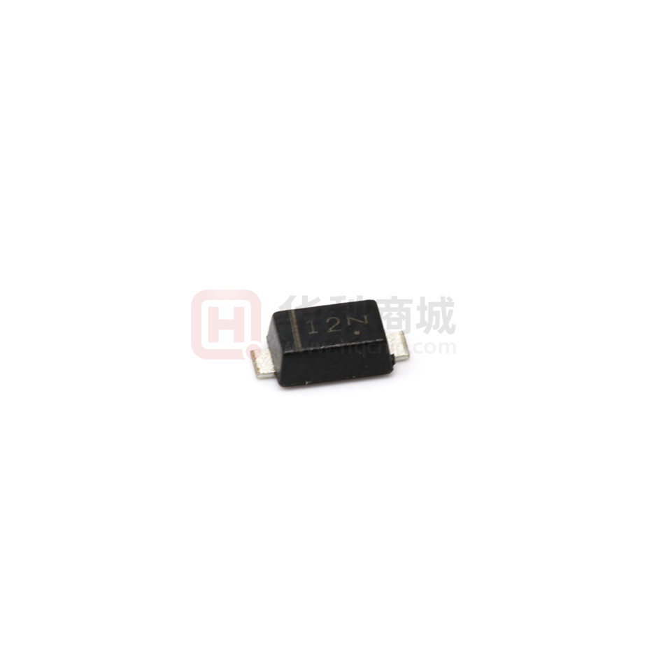
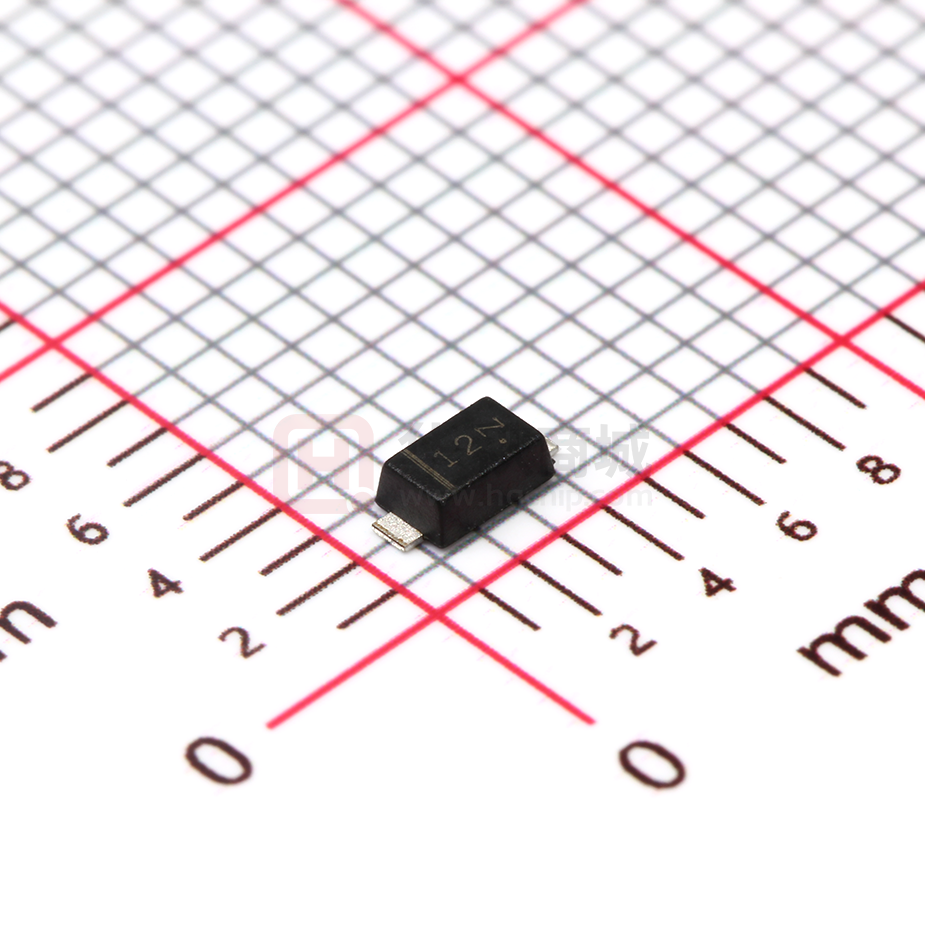
Case: SOD123-FL/MINI SMA
molded plastic over sky die
Terminals: Tin Plated, solderable per
MIL-STD-750, Method 2026
Polarity: Color band denotes cathode end
Mounting Position: Any
Weight: 0.0155 g
Handling precautin:None
We declare that the material of product is
Haloggen free (green epoxy compound)
1.Electrical Characteristic
Maximum & Thermal Characteristics Ratings at 25°C ambient temperature unless otherwise specified.
Parameter Symbol
symbol
device marking code
LMBR
120
FT1G
LMBR
130
FT1G
LMBR
140
FT1G
LMBR
145
FT1G
LMBR
150
FT1G
LMBR
160
FT1G
LMBR
180
FT1G
LMBR
1100
FT1G
LMBR
1150
FT1G
LMBR
1200
FT1G
12
13
14
145
15
16
18
110
115
120
100
150
200
Unit
Maximum repetitive peak reverse
voltage
VRRM
20
30
40
45
50
60
80
Maximum RMS voltage
VRMS
14
21
28
31.5
35
42
56
70
105
140
V
Maximum DC blocking voltage
VDC
20
30
40
45
50
60
80
100
150
200
V
Maximum average forward rectified
current at TC = 75°C
IF(AV)
1.0
A
Peak forward surge current 8.3ms
single half sine-wave superimposed
on rated load (JEDEC Method)
IFSM
30
A
Typical thermal resistance (Note 1)
RθJA
RθJC
110
40
°C/W
TJ
–55 to +150
°C
TSTG
–65 to +175
°C
Operating junction temperature range
storage temperature range
V
Electrical Characteristics Ratings at 25°C ambient temperature unless otherwise specified.
Parameter Symbol
symbol
LMBR
120
FT1G
LMBR
130
FT1G
0.5
0.35
0.45
0.50
LMBR
140
FT1G
LMBR
145
FT1G
LMBR
150
FT1G
LMBR
160
FT1G
LMBR
180
FT1G
LMBR
1100
FT1G
LMBR
1150
FT1G
LMBR
1200
FT1G
0.90
0.92
Unit
Maximum instantaneous forward
voltage at(IF = 0.1 A, TJ = 25°C)
(IF = 0.7 A, TJ = 25°C)
(IF = 1.0 A, TJ = 25°C)
VF
Maximum DC reverse current at rated
DC blocking voltage TA = 25°C
Tj = 125°C
IR
0.5
10
mA
Typical junction capacitance at
4.0V, 1MHz
CJ
160
PF
NOTES:
1. 8.0mm2 (.013mm thick) land areas
0.55
0.7
0.85
V
�LMBR120FT1G thru LMBR1200FT1G
2.Ratings and Characteristic Curves ( TA = 25°C unless otherwise noted )
Fig. 2 – Maximum Non-repetitive Peak
Forward Surge Current
60 Hz
Resistive or
Inductive Load
1.0
0.5
Peak forward surge current (A)
Average Forward Rectified Current (A)
Fig. 1 – Forward Current Derating Curve
30
15
0
0
100
25 50 75 100 125 150 175
CASE TEMPERATURE:Tc(°C)
Fig 3. – Typical Instantaneous Forward
Characteristics
TJ = 25°C
Pulse width = 300µs
1% Duty Cycle
10
1.0
0.1
1
10
Tj=125
1.0
Tj=75
0.1
0.01
0.01
0.2
Tj=25
0.001
0
20
40
60
80
100
Percent of Rated Peak Reverse Voltage (%)
0.4
0.6
0.8
1.0
Instantaneous Forward Voltage (V)
Fig 5. –typical transient thermal
impedance
Fig 6. – Typical Junction Capacitance
1000
Junction Capacitance (pF)
100
10
Number of Cycles at 60Hz
Fig 4. – Typical Reverse Characteristics
Instantaneous Reverse Current (mA)
Instantaneous Forward Current (A)
0
Transient thermal impedance(°C/W)
TJ = TJ max
8.3ms Single
Half Sine-
10
1.0
TJ = 25°C
f = 1.0 MHz
Vsig =
50 V
100
10
0.1
0.01
0.1
1.0
10
t,Pulse duration,sec
0.1
1
Reverse Voltage (V)
10
100
�LMBR120FT1G thru LMBR1200FT1G
3. dimension:
SOD123-FL
MILLIMETERS
MIN
MAX
3.5
3.9
0.75
0.95
2.6
3.0
1.6
2.0
0.45Typ
0.9
1.2
0.12
0.22
0.8Typ
DIM
A
B
C
D
E
H
J
K
INCHES
MIN
MAX
0.138
0.159
0.029
0.037
0.103
0.119
0.063
0.079
0.018Typ
0.036
0.047
0.005
0.009
0.032Typ
Suggested solder pad layout
B
C
A
Dimensions in inches and (millimeters)
PACKAGE
A
B
C
SOD123-FL
0.044(1.10
0.040(1.00)
0.079(2.00)
�LMBR120FT1G thru LMBR1200FT1G
4.Packing information
Unit:mm
Symbol
tolerance
SOD123-FL
Carrier width
A
0.1
2.00
Carrier length
B
0.1
3.85
Carrier depth
C
0.1
1.10
Sprocket hole
d
0.1
1.50
13" Reel outside diameter
D
2.0
-
13" Reel inner diameter
D1
min
-
7" Reel outside diameter
D
2.0
178.00
7" Reel inner diameter
D1
min
62.00
Feed hole diameter
D2
0.5
13.00
Sprocket hole position
E
0.1
1.75
Punch hole position
F
0.1
3.50
Punch hole pitch
P
0.1
4.00
Spocket hole pitch
P0
0.1
4.00
Embossment center
P1
0.1
2.00
Overall tape thickness
T
0.1
0.23
Tape width
W
0.3
8.00
Reel width
W1
1.0
11.40
Item
�LMBR120FT1G thru LMBR1200FT1G
Reel packing
PACKAGE
REEL SIZE
SOD123-FL
7"
REEL
COMPONENT
APPOX.
BOX
INNER BOX
REEL DIA.
CARTON SIZE
CARTON
(PCS)
SPACING
(mm)
(pcs)
(mm)
(mm)
(mm)
(PCS)
GROSS WEIGHT
(kg)
3,000
4.0
30,000
183*183*123
178
382*262*387
240,000
8.7
5.Suggested thermal profile for soldering process
1. Storage environment:Temperature=5~40℃ Humidity=55±25%
2. Reflow soldering of surface-mount device
3. Reflow soldering
Profile Feature
Soldering Condition
Average ramp-up rate(TL to TP)
很抱歉,暂时无法提供与“LMBR120FT1G”相匹配的价格&库存,您可以联系我们找货
免费人工找货- 国内价格
- 20+0.23251
- 200+0.18702
- 600+0.16174
- 国内价格
- 1+0.16375
- 30+0.15750
- 100+0.15125
- 500+0.13875
- 1000+0.13250
- 2000+0.12875


 工商网监
湘ICP备2023018690号
工商网监
湘ICP备2023018690号

