AN3134
Application note
EVAL6229QR demonstration board using the L6229Q DMOS
driver for a three-phase BLDC motor control application
Introduction
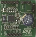
This application note describes the EVAL6229QR demonstration board for the L6229Q
DMOS fully integrated three-phase brushless DC motor driver. The board implements a
typical application that can be used as a demonstration platform for driving three-phase
brushless DC motors with currents up to 1 A DC.
Thanks to the small footprint of the L6229Q (QFN 5x5 mm), the board is a very compact
30x32 mm.
Figure 1.
April 2010
EVAL6229QR demonstration board
Doc ID 16960 Rev 1
1/10
www.st.com
�Demonstration board description
1
Demonstration board description
Table 1.
2/10
AN3134
EVAL6229QR pin description
Name
Type
Function
VS
Power supply
PGND
Ground
VDD
Power supply
Hall effect sensors pull-up voltage.
H1
Sensor input
Single ended hall effect sensor input 1.
H2
Sensor input
Single ended hall effect sensor input 2.
H3
Sensor input
Single ended hall effect sensor input 3.
SGND
Ground
DIAG
Open-drain output
Diagnostic pin. When ‘low’, signals an overcurrent or
overtemperature event.
TACHO
Open-drain output
Frequency-to-voltage open drain output. Every pulse from H1 pin is
shaped as a fixed and adjustable length pulse.
F/R
Logic input
EN
Logic input/output
VREF
Analog input
BRAKE
Logic input
OUT1
Power output
Output phase 1.
OUT2
Power output
Output phase 2.
OUT3
Power output
Output phase 3.
Hal bridges power supply voltage
Power ground terminal.
Signal ground terminal.
Selects the direction of the rotation (‘H’ = CW; ‘L’ = CCW).
Chip enable (active ‘high’). When ‘low’, switches OFF all power
MOSFETs of three half-bridges.
Current controller reference voltage.
Brake input pin. When ‘low, switches ON all high-side power
MOSFETs implementing the brake function.
Doc ID 16960 Rev 1
�AN3134
Demonstration board description
Figure 2.
EVAL6229QR demonstration board pin locations
The decoding logic integrated in the device is a combinatory logic which provides the
appropriate driving signals for the three-phase bridge outputs, based on the signals coming
from the three hall sensors H1, H2 and H3. The hall sensors detect rotor position in a 3phase BLDC motor.
The EN pin connected to the diagnostic output DIAG is used to implement the overcurrent
and thermal protection.
To perform PWM current control, an analog reference voltage should be provided at the
VREF pin. A fixed reference voltage can be easily obtained through a resistor divider from
an external voltage rail and GND (possibly that which supplies the microcontroller or the rest
of the application). Alternatively, a very simple way of obtaining a variable voltage without
using a DAC is to low-pass filter the PWM output of a microcontroller.
Table 2 summarizes the electrical specifications of the application, Figure 3 shows the
electrical schematic, and Table 3 provides the component list.
Doc ID 16960 Rev 1
3/10
�Demonstration board description
Table 2.
AN3134
EVAL6229QR: electrical specifications (recommended values)
Parameter
Value
Unit
8 to 52
Vdc
RMS output current rating (OUTx)
up to 1.4
A
Switching frequency
up to 100
kHz
Voltage reference range (VREF)
0 to +5
V
Input and enable voltage range
0 to +5
V
-25 to +125
°C
42
°C/W
Supply voltage range (VS)
Operating temperature range
L6229Q thermal resistance junction-to-ambient
4/10
Doc ID 16960 Rev 1
�(1
5�
Doc ID 16960 Rev 1
7$&+2
95()
',$*
6*1'
9''
&�
5��
��
+�
5�
��
+�
5�
��
+�
��
��
��
5�
5�
)�5
%5$.(
5�
5�
5��
/����4
+�
+�
+�
):5�5(:
%5$.(
(1
&�
&�
�
'�
5�
&�
&�
�
8�
5�
',$*
��
*1'
&�
5��
95()
��
��
9%227
5&2))
��
�
�
9&3
7$&+2
�
��
96$
5&38/6(
��
��
96%
6(16($
��
��
6(16(%
��
*1'
1&
1&
1&
287�
287�
287�
1&���(3$'
1&���(3$'
1&���(3$'
1&���(3$'
1&���(3$'
1&���(3$'
1&���(3$'
287�
287�
��
��
��
��
287�
��
3*1'
��
�
�
�
�
�
�
�
&�
96
Figure 3.
��
&�
AN3134
Demonstration board description
EVAL6229QR demonstration board schematic
!-�����V�
5/10
�Demonstration board description
Table 3.
AN3134
EVAL6229QR component list
Part reference
Part value
Part description
C1
220nF/100V
Capacitor
C2
100µF/63V
Capacitor
C3
10nF/25V
Capacitor
C4, C8
220nF/25V
Capacitor
C5
5.6nF
Capacitor
C6
820pF
Capacitor
C7
10nF
Resistor
D1
BAT46SW
Diodes
R1, R2, R3, R4
100kΩ 5% 0.25W
Resistor
R5, R6, R7
10kΩ 5% 0.25W
Resistor
R8
100kΩ 1% 0.25W
Resistor
R9
20kΩ 1% 0.25W
Resistor
R10
0.4Ω 1W
Resistor
R11
20kΩ 5% 0.25W
Resistor
R12
2kΩ 5% 0.25W
Resistor
U1
L6229Q
3-phase BLDC motor driver in VFQFPN5x5
The input lines EN, BRAKE and F/R are connected to ground through a pull-down resistor
which sets the default logic level to “low”. An external signal can be applied to change each
input status. The Hall effect inputs H1, H2 and H3 have a pull-up resistor connected to the
VDD voltage, which can be provided by the VDD pin.
A charge pump circuit, made up of D1, C3 and C4, generates the supply voltage for the
high-side integrated MOSFETs. Due to voltage and current switching at relatively high
frequency, these components are connected through short paths in order to minimize
induced noise in other circuits.
R4 and C5 are used by the integrated overcurrent protection circuitry to set the protection
timings (disable time tDISABLE is about 200 µs and delay time tDELAY is about 1 µs, based on
the values in Table 3).
R8 and C6 are used to set the off-time tOFF of the PWM to about 50 µs. When changing the
RC network value, the off-time should be adjusted according to the electrical characteristics
and supply voltage of the motor.
R11, R12 and C8 are low-pass filters to provide an external reference voltage through the
PWM output of a microcontroller.
R9 and C7 are used to set the off-time tPULSE of the TACHO pin. The TACHO output signal
can be used to implement a simple frequency-to-voltage converter (speed loop control).
Figure 4, Figure 5 and Figure 6 show the component placement and the two-layer layout of
the EVAL6229QR demonstration board. A GND area is used for the IC power dissipation.
6/10
Doc ID 16960 Rev 1
�AN3134
Demonstration board description
Figure 4.
EVAL6229QR component placement
Figure 5.
EVAL6229QR top layer layout
Doc ID 16960 Rev 1
7/10
�Demonstration board description
Figure 6.
8/10
AN3134
EVAL6229QR bottom layer layout
Doc ID 16960 Rev 1
�AN3134
2
Revision history
Revision history
Table 4.
Document revision history
Date
Revision
13-Apr-2010
1
Changes
Initial release.
Doc ID 16960 Rev 1
9/10
�AN3134
Please Read Carefully:
Information in this document is provided solely in connection with ST products. STMicroelectronics NV and its subsidiaries (“ST”) reserve the
right to make changes, corrections, modifications or improvements, to this document, and the products and services described herein at any
time, without notice.
All ST products are sold pursuant to ST’s terms and conditions of sale.
Purchasers are solely responsible for the choice, selection and use of the ST products and services described herein, and ST assumes no
liability whatsoever relating to the choice, selection or use of the ST products and services described herein.
No license, express or implied, by estoppel or otherwise, to any intellectual property rights is granted under this document. If any part of this
document refers to any third party products or services it shall not be deemed a license grant by ST for the use of such third party products
or services, or any intellectual property contained therein or considered as a warranty covering the use in any manner whatsoever of such
third party products or services or any intellectual property contained therein.
UNLESS OTHERWISE SET FORTH IN ST’S TERMS AND CONDITIONS OF SALE ST DISCLAIMS ANY EXPRESS OR IMPLIED
WARRANTY WITH RESPECT TO THE USE AND/OR SALE OF ST PRODUCTS INCLUDING WITHOUT LIMITATION IMPLIED
WARRANTIES OF MERCHANTABILITY, FITNESS FOR A PARTICULAR PURPOSE (AND THEIR EQUIVALENTS UNDER THE LAWS
OF ANY JURISDICTION), OR INFRINGEMENT OF ANY PATENT, COPYRIGHT OR OTHER INTELLECTUAL PROPERTY RIGHT.
UNLESS EXPRESSLY APPROVED IN WRITING BY AN AUTHORIZED ST REPRESENTATIVE, ST PRODUCTS ARE NOT
RECOMMENDED, AUTHORIZED OR WARRANTED FOR USE IN MILITARY, AIR CRAFT, SPACE, LIFE SAVING, OR LIFE SUSTAINING
APPLICATIONS, NOR IN PRODUCTS OR SYSTEMS WHERE FAILURE OR MALFUNCTION MAY RESULT IN PERSONAL INJURY,
DEATH, OR SEVERE PROPERTY OR ENVIRONMENTAL DAMAGE. ST PRODUCTS WHICH ARE NOT SPECIFIED AS "AUTOMOTIVE
GRADE" MAY ONLY BE USED IN AUTOMOTIVE APPLICATIONS AT USER’S OWN RISK.
Resale of ST products with provisions different from the statements and/or technical features set forth in this document shall immediately void
any warranty granted by ST for the ST product or service described herein and shall not create or extend in any manner whatsoever, any
liability of ST.
ST and the ST logo are trademarks or registered trademarks of ST in various countries.
Information in this document supersedes and replaces all information previously supplied.
The ST logo is a registered trademark of STMicroelectronics. All other names are the property of their respective owners.
© 2010 STMicroelectronics - All rights reserved
STMicroelectronics group of companies
Australia - Belgium - Brazil - Canada - China - Czech Republic - Finland - France - Germany - Hong Kong - India - Israel - Italy - Japan Malaysia - Malta - Morocco - Philippines - Singapore - Spain - Sweden - Switzerland - United Kingdom - United States of America
www.st.com
10/10
Doc ID 16960 Rev 1
�


 工商网监
湘ICP备2023018690号
工商网监
湘ICP备2023018690号
