Additional Resources:
Product Page
|
3D Model
date
06/08/2015
page
1 of 6
SERIES: VSK-S10│ DESCRIPTION: AC-DC POWER SUPPLY
FEATURES
•
•
•
•
•
•
•
up to 10 W continuous power
compact board mount design
universal input (85~264 Vac / 100~370 Vdc)
single output from 3.3~24 Vdc
over current and short circuit protections
UL/cUL safety approvals
efficiency up to 83%
MODEL
VSK-S10-3R3UA
output
voltage
output
current
output
power
ripple
and noise1
efficiency
(Vdc)
max
(A)
max
(W)
max
(mVp-p)
max
(%)
3.3
2
6.6
100
72
VSK-S10-5UA
5
2
10
100
76
VSK-S10-9UA
9
1.1
10
100
80
VSK-S10-12UA
12
0.9
10
100
81
VSK-S10-15UA
15
0.7
10
100
82
VSK-S10-24UA
24
0.45
10
100
83
Notes:
1. Ripple and noise are measured at 20 MHz BW by “parallel cable” method with 1 μF ceramic and 10 μF electrolytic capacitors on the output.
PART NUMBER KEY
VSK-S10 - XXUA
Base Number
Output Voltage
cui.com
�Additional Resources:
Product Page
|
3D Model
CUI Inc │ SERIES: VSK-S10│ DESCRIPTION: AC-DC POWER SUPPLY
date 06/08/2015 │ page 2 of 6
INPUT
parameter
conditions/description
min
voltage
frequency
max
units
85
100
typ
264
370
Vac
Vdc
47
440
Hz
current
at 110 Vac
at 230 Vac
230
150
mA
mA
inrush current
at 110 Vac
at 230 Vac
10
20
A
A
input fuse
recommended external 2 A/250 V, slow-blow type
±0.02
%/°C
0.5
W
temperature coefficient
no load power consumption
OUTPUT
parameter
conditions/description
capcitive load
3.3 Vdc model
5 Vdc model
9 Vdc model
12 Vdc model
15 Vdc model
24 Vdc model
min
line regulation
full load
±0.5
%
load regulation
at 10 ~ 100%
±1
%
voltage set accuracy
3.3 Vdc model
all other models
±3
±2
%
%
hold-up time
at 230 Vac
80
ms
65
kHz
switching frequency
typ
max
units
15,000
12,000
6000
2000
1500
500
μF
μF
μF
μF
μF
μF
PROTECTIONS
parameter
conditions/description
over voltage protection
3.3, 5 Vdc models
9 Vdc model
12, 15 Vdc models
24 Vdc model
min
over current protection
short circuit protection
typ
max
units
7.5
15
20
30
Vdc
Vdc
Vdc
Vdc
110
%
auto recovery
SAFETY & COMPLIANCE
parameter
conditions/description
isolation voltage
input to output
safety approvals
UL60950-1
safety class
Class II
conducted emissions
CISPR11/EN55011, Class A, CISPR11/EN55011, Class B (external circuit required, see figure 2)
radiated emissions
CISPR11/EN55011, Class A, CISPR11/EN55011, Class B (external circuit required, see figure 2)
ESD
IEC/EN61000-4-2 Class B, ±6KV/8KV
radiated immunity
IEC/EN61000-4-3 Class A, 10V/m
EFT/burst
surge
conducted immunity
min
typ
max
units
4,000
IEC/EN61000-4-4 Class B, ±2 kV
IEC/EN61000-4-4 Class B, ±4 kV (external circuit required, see figure 2)
IEC/EN61000-4-5 Class B, ±1 kV (external circuit required, see figure 1)
IEC/EN61000-4-5 Class B, ±2 kV / ±4 kV (external circuit required, see figure 2)
IEC/EN61000-4-6 Class A, 10 Vr.m.s
cui.com
Vac
�Additional Resources:
Product Page
|
3D Model
CUI Inc │ SERIES: VSK-S10│ DESCRIPTION: AC-DC POWER SUPPLY
date 06/08/2015 │ page 3 of 6
SAFETY & COMPLIANCE (CONTINUED)
parameter
conditions/description
PFM
IEC/EN61000-4-8 Class A, 10 A/m
min
voltage dips & interruptions
IEC/EN61000-4-11 Class B, 0%-70%
MTBF
as per MIL-HDBK-217F at 25 °C
RoHS
2011/65/EU
typ
max
units
300,000
hours
ENVIRONMENTAL
parameter
conditions/description
min
operating temperature
see derating curves
storage temperature
typ
max
units
-25
70
°C
-25
105
°C
95
%
storage humidity
DERATING CURVES
load vs. input voltage (Vac)
60
50
40
20
80
75
Load (%)
Load (%)
80
70
Safe operating area
60
40
55
70
~
~
0
Ambient Temperature (°C)
85
80
75
Safe operating area
60
40
20
20
-25
~
~
100
~
~
~
~
100
~
~
Load (%)
100
load vs. input voltage (Vdc)
100
240
Input Voltage (Vac)
cui.com
264
100
120
~
~
load vs. ambient temperature
340
Input Voltage (Vdc)
370
�Additional Resources:
Product Page
|
3D Model
CUI Inc │ SERIES: VSK-S10│ DESCRIPTION: AC-DC POWER SUPPLY
date 06/08/2015 │ page 4 of 6
MECHANICAL
parameter
conditions/description
dimensions
53.80 x 28.80 x 19 (2.118 x 1.134 x 0.748 inch)
min
material
UL94V-0
weight
typ
units: mm [inch]
tolerance: ±0.50 [±0.020]
pin section tolerance: ±0.10 [±0.004]
PIN CONNECTIONS
PIN
FUNCTION
1
AC(N)
2
AC(L)
3
+Vo
4
-Vo
cui.com
units
mm
50
MECHANICAL DRAWING
max
g
�Additional Resources:
Product Page
|
3D Model
CUI Inc │ SERIES: VSK-S10│ DESCRIPTION: AC-DC POWER SUPPLY
date 06/08/2015 │ page 5 of 6
TYPICAL APPLICATION CIRCUIT
Figure 1
NT C
FUS E
AC(L)
A C (L)
C1 C2
+Vo
T VS
+
RL
MOV
-Vo
AC(N )
A C (N )
Table 1
Recommended External Circuit Components
Note:
MODEL
C11
C21
TVS
FUSE
MOV
NTC
VSK-S10-3R3UA
1 μF/50V
220 μF/10V
SMBJ7.0A
2A/250V
S14K300
10D-10
VSK-S10-5UA
1 μF/50V
220 μF/10V
SMBJ7.0A
2A/250V
S14K300
10D-10
VSK-S10-9UA
1 μF/50V
120 μF/25V
SMBJ12A
2A/250V
S14K300
10D-10
VSK-S10-12UA
1 μF/50V
120 μF/25V
SMBJ20A
2A/250V
S14K300
10D-10
VSK-S10-15UA
1 μF/50V
120 μF/25V
SMBJ20A
2A/250V
S14K300
10D-10
VSK-S10-24UA
1 μF/50V
68 μF/35V
SMBJ30A
2A/250V
S14k300
10D-10
1. Output filtering capacitor C1 is a ceramic capacitor that is used to filter high frequency noise. C2 is an electrolytic capacitor. It is recommended to use high frequency and
low impedance electrolytic capacitors. For capacitance and current of capacitor please refer to the manufacturer’s datasheet. Voltage derating of capacitor should be 80%
or above.
EMC RECOMMENDED CIRCUIT
Figure 2
AC(L)
L1
FU SE
LCM
R1
AC(L)
CY1
+Vo
C1 C2
+
CX
MOV
CY2
AC/DC
RL
-Vo
AC(N )
AC(N )
TVS
Table 2
Recommended External Circuit Components
FUSE
MOV
CY1, CY2
CX
LCM
L1
R1
C1, C2,
TVS
2A/250 Vdc slow fusing
S14K300
1nF/400VAC
0.1μF/275VAC
2.2mH
4.7μH/2.0A
12Ω/3W
see Table 1
see Table 1
Note:
1. All specifications measured at Ta=25°C, humidity
很抱歉,暂时无法提供与“VSK-S10-5UA”相匹配的价格&库存,您可以联系我们找货
免费人工找货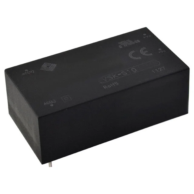


 工商网监
湘ICP备2023018690号
工商网监
湘ICP备2023018690号

