0.1 GHz to 8 GHz,
GaAs, Nonreflective, SP4T Switch
HMC344ALP3E
Data Sheet
FUNCTIONAL BLOCK DIAGRAM
13 NIC
12 RF1
NIC 2
11 NIC
NIC 3
10 NIC
RF2
PACKAGE
BASE
GND
14305-001
9
CTLA 8
CTLB 7
2:4
DECODER
GND 5
Broadband telecommunications systems
Fiber optics
Switched filter banks
Wireless Infrastructure below 8 GHz
14 GND
RF4 1
RF3 4
APPLICATIONS
15 RFC
HMC344ALP3E
VEE 6
Broadband frequency range: 0.1 GHz to 8 GHz
Nonreflective 50 Ω design
Low insertion loss: 1.7 dB at 6 GHz
High isolation: 36 dB at 6 GHz
High input linearity at 250 MHz to 8 GHz
P1dB: 28 dBm typical
IP3: 44 dBm typical
Integrated 2 to 4 line decoder
16-lead, 3 mm × 3 mm LFCSP package
ESD HBM rating: 250 V (Class 1A)
16 GND
FEATURES
Figure 1.
GENERAL DESCRIPTION
The HMC344ALP3E is a broadband, nonreflective, single-pole,
four-throw (SP4T) switch manufactured using a gallium arsenide
(GaAs) metal semiconductor field effect transistor (MESFET)
process. This switch offers high isolation, low insertion loss, and
on-chip termination of the isolated ports.
The HMC344ALP3E includes an on-chip, binary two-line to
four-line decoder that provides logic control from two logic
input lines.
The HMC344ALP3E comes in a 3 mm × 3 mm, 16-lead LFCSP
package and operates from a 0.1 GHz to 8 GHz frequency range.
The switch operates with a negative supply voltage (VEE) range
of −5 V to −3 V and requires two negative logic control
voltages.
Rev. A
Document Feedback
Information furnished by Analog Devices is believed to be accurate and reliable. However, no
responsibility is assumed by Analog Devices for its use, nor for any infringements of patents or other
rights of third parties that may result from its use. Specifications subject to change without notice. No
license is granted by implication or otherwise under any patent or patent rights of Analog Devices.
Trademarks and registered trademarks are the property of their respective owners.
One Technology Way, P.O. Box 9106, Norwood, MA 02062-9106, U.S.A.
Tel: 781.329.4700
©2017 Analog Devices, Inc. All rights reserved.
Technical Support
www.analog.com
�HMC344ALP3E
Data Sheet
TABLE OF CONTENTS
Features .............................................................................................. 1
Typical Performance Charcteristics ................................................6
Applications ....................................................................................... 1
Insertion Loss, Return Loss, and Isolation ................................6
Functional Block Diagram .............................................................. 1
Input Power Compression and Input IP3 ..................................7
General Description ......................................................................... 1
Theory of Operation .........................................................................8
Revision History ............................................................................... 2
Applications Information .................................................................9
Specifications..................................................................................... 3
Evaluation Board ...........................................................................9
Absolute Maximum Ratings ............................................................ 4
Outline Dimensions ....................................................................... 11
ESD Caution .................................................................................. 4
Ordering Guide .......................................................................... 11
Pin Configuration and Function Descriptions ............................. 5
Interface Schematics..................................................................... 5
REVISION HISTORY
This Hittite Microwave Products data sheet has been reformatted
to meet the styles and standards of Analog Devices, Inc.
12/2017—Rev. 01.0316 to Rev. A
Changes to Features Section, Figure 1, and General Description
Section ................................................................................................ 1
Changes to Table 1 ............................................................................ 3
Changes to Table 2 ............................................................................ 4
Changes to Figure 2, Table 3, and Figure 4 .................................. 5
Added Figure 3 and Figure 5; Renumbered Sequentially ........... 5
Added Insertion Loss, Return Loss, and Isolation Section and
Figure 8 .............................................................................................. 6
Changes to Figure 6, Figure 7, and Figure 9.................................. 6
Added Input Power Compression and Input 1P3 Section, Figure 12,
and Figure 13 .......................................................................................7
Changes to Figure 10 and Figure 11 ...............................................7
Added Theory of Operation Section .............................................8
Changes to Table 4.............................................................................8
Added Figure 14 ................................................................................9
Changes to Evaluation Board Section, Figure 15, and Table 5 ....9
Changes to Figure 16...................................................................... 10
Added Figure 17 ............................................................................. 10
Updated Outline Dimensions ....................................................... 11
Changes to Ordering Guide ......................................................... 11
Rev. A | Page 2 of 11
�Data Sheet
HMC344ALP3E
SPECIFICATIONS
VEE = −3 V or −5 V, control voltage (VCTL) = 0 V or VEE, case temperature (TCASE) = 25°C, 50 Ω system, unless otherwise noted.
Table 1.
Parameter
FREQUENCY RANGE
INSERTION LOSS
Between RFC and RF1 to RF4 (On)
Symbol
f
RETURN LOSS
RFC and RF1 to RF4 (On)
Third-Order Intercept
SUPPLY
Voltage
Current
DIGITAL CONTROL INPUTS
Voltage
Low
1
Min
0.1
0.1 GHz to 2 GHz
2 GHz to 4 GHz
4 GHz to 6 GHz
6 GHz to 8 GHz
ISOLATION
Between RFC and RF1 to RF4 (Off )
RF1 to RF4 (Off )
SWITCHING
Rise and Fall Time
On and Off Time
INPUT LINEARITY1
1 dB Power Compression
Test Conditions/Comments
tRISE, tFALL
tON, tOFF
P1dB
IP3
Typ
Max
8
Unit
GHz
1.4
1.4
1.7
2.1
2.0
2.0
2.2
2.5
dB
dB
dB
dB
0.1 GHz to 2 GHz
2 GHz to 4 GHz
4 GHz to 6 GHz
6 GHz to 8 GHz
39
33
32
28
43
37
36
32
dB
dB
dB
dB
0.1 GHz to 2 GHz
2 GHz to 4 GHz
4 GHz to 6 GHz
6 GHz to 8 GHz
0.1 GHz to 8 GHz
12
12
11
6
11
16
16
16
11
16
dB
dB
dB
dB
dB
35
75
ns
ns
23
28
25
dBm
dBm
40
44
44
dBm
dBm
10% to 90% of radio frequency (RF) output
50% VCTL to 90% of RF output
f = 250 MHz to 8 GHz
VEE = −5 V
VEE = −3 V
10 dBm per tone, 1 MHz spacing
VEE = −5 V
VEE = −3 V
VEE pin
VEE
IEE
−5
2.5
−3
6
V
mA
0
0
−4.2
−2.2
V
V
V
V
CTLA and CTLB pins
VCTL
VINL
High
VINH
Current
Low
High
ICTL
IINL
IINH
VEE = −5 V
VEE = −3 V
VEE = −5 V
VEE = −3 V
−3
−1
−5
−3
40
0.10
Input linearity performance degrades at frequencies less than 250 MHz.
Rev. A | Page 3 of 11
µA
µA
�HMC344ALP3E
Data Sheet
ABSOLUTE MAXIMUM RATINGS
For recommended operating conditions, see Table 1.
Table 2.
Parameter
Negative Supply Voltage (VEE)
Digital Control Input Voltage Range
RF Input Power
f = 250 MHz to 8 GHz, TCASE = 85°C
VEE = −5 V
Through Path
Terminated Path
Hot Switching
VEE = −3 V
Through Path
Terminated Path
Hot Switching
Temperature
Junction, TJ
Storage
Reflow
Junction to Case Thermal Resistance, θJC
Through Path
Terminated Path
Electrostatic Discharge (ESD) Sensitivity
Human Body Model (HBM)
Rating
−7 V
VEE − 0.5 V to +1 V
Stresses at or above those listed under Absolute Maximum
Ratings may cause permanent damage to the product. This is a
stress rating only; functional operation of the product at these
or any other conditions above those indicated in the operational
section of this specification is not implied. Operation beyond
the maximum operating conditions for extended periods may
affect product reliability.
ESD CAUTION
28 dBm
26.5 dBm
22 dBm
25 dBm
23.5 dBm
19 dBm
150°C
−65°C to +150°C
260°C
107°C/W
137°C/W
250 V (Class 1A)
Rev. A | Page 4 of 11
�Data Sheet
HMC344ALP3E
PIN CONFIGURATION AND FUNCTION DESCRIPTIONS
13 NIC
14 GND
16 GND
15 RFC
HMC344ALP3E
RF4 1
NIC 3
12 RF1
TOP VIEW
Not to Scale
11 NIC
10 NIC
9
RF2
CTLA 8
CTLB 7
VEE 6
GND 5
RF3 4
NOTES
1. NIC = NOT INTERNALLY CONNECTED. THESE PINS
ARE NOT CONNECTED INTERNALLY; HOWEVER, ALL
DATA SHOWN IN THIS DATA SHEET IS MEASURED
WHEN THESE PINS ARE CONNECTED TO THE RF/DC
GROUND EXTERNALLY.
2. EXPOSED PAD. THE EXPOSED PAD MUST BE
CONNECTED TO THE RF/DC GROUND OF THE PCB.
14305-002
NIC 2
Figure 2. Pin Configuration
Table 3. Pin Function Descriptions
Pin No.
1
Mnemonic
RF4
2, 3, 10, 11, 13
NIC
4
RF3
5, 14, 16
6
7
8
9
GND
VEE
CTLB
CTLA
RF2
12
RF1
15
RFC
EPAD
Description
RF4 Port. This pin is dc-coupled and matched to 50 Ω. A dc blocking capacitor is required if the RF line
potential does not equal 0 V dc.
Not Internally Connected. These pins are not connected internally; however, all data shown in this data
sheet is measured when these pins are connected to the RF/dc ground externally.
RF3 Port. This pin is dc-coupled and matched to 50 Ω. A dc blocking capacitor is required if the RF line
potential does not equal 0 V dc.
Ground. These pins connect to the RF/dc ground of the PCB.
Negative Supply Voltage Pin.
Control Input 2 Pin. See Table 4 for the control voltage truth table.
Control Input 1 Pin. See Table 4 for the control voltage truth table.
RF2 Port. This pin is dc-coupled and matched to 50 Ω. A dc blocking capacitor is required if the RF line
potential does not equal 0 V dc.
RF1 Port. This pin is dc-coupled and matched to 50 Ω. A dc blocking capacitor is required if the RF line
potential does not equal 0 V dc.
RF Common Port. This pin is dc-coupled and matched to 50 Ω. A dc blocking capacitor is required if the RF
line potential does not equal 0 V dc.
Exposed Pad. The exposed pad must be connected to the RF/dc ground of the PCB.
INTERFACE SCHEMATICS
5Ω
Figure 3. RFC and RF1 to RF4 Interface Schematic
600Ω
Figure 5. VEE Interface Schematic
100kΩ
14305-004
CTLA,
CTLB
14305-005
1.6pF
VEE
14305-003
RFC,
RF1,
RF2,
RF3,
RF4
Figure 4. CTLA and CTLB Interface Schematic
Rev. A | Page 5 of 11
�HMC344ALP3E
Data Sheet
TYPICAL PERFORMANCE CHARCTERISTICS
0
0
–1
–1
–2
–3
–2
–3
–4
–4
RFC TO
RFC TO
RFC TO
RFC TO
+85°C
+25°C
–40°C
0
1
2
3
4
5
6
7
8
9
FREQUENCY (GHz)
–5
14305-006
–5
0
1
2
3
4
5
6
7
8
9
FREQUENCY (GHz)
Figure 6. Insertion Loss vs. Frequency at Various Temperatures,
Between RFC and RF1
Figure 8. Insertion Loss vs. Frequency, Between RFC and RFx
0
0
–5
–10
RFC TO
RFC TO
RFC TO
RFC TO
RF1
RF2
RF3
RF4
–20
ISOLATION (dB)
–10
–15
–20
–25
–30
–40
–50
–60
RFC
RF1 TO RF4 ON
RF1 TO RF4 OFF
–70
–35
0
1
2
3
4
5
6
7
8
FREQUENCY (GHz)
9
Figure 7. Return Loss vs. Frequency for RFC, RF1 to RF4 On,
and RF1 to RF4 Off
–80
0
1
2
3
4
5
6
7
8
FREQUENCY (GHz)
Figure 9. Isolation vs. Frequency, Between RFC and RFx
Rev. A | Page 6 of 11
9
14305-009
–30
14305-007
RETURN LOSS (dB)
RF1
RF2
RF3
RF4
14305-008
INSERTION LOSS (dB)
INSERTION LOSS (dB)
INSERTION LOSS, RETURN LOSS, AND ISOLATION
�Data Sheet
HMC344ALP3E
30
30
27
27
INPUT COMPRESSION (dB)
24
21
21
18
P1dB AT +85°C
P1dB AT +25°C
P1dB AT –40°C
P0.1dB AT +85°C
P0.1dB AT +25°C
P0.1dB AT –40°C
P1dB AT +85°C
P1dB AT +25°C
P1dB AT –40°C
0
1
2
3
4
5
6
7
8
FREQUENCY (GHz)
15
14305-010
15
Figure 10. Input Compression vs. Frequency at Various Temperatures,
VEE = −5 V
0
2
3
4
5
6
7
8
Figure 12. Input Compression vs. Frequency at Various Temperatures,
VEE = −3 V
45
45
INPUT IP3 (dB)
47
41
1
FREQUENCY (GHz)
47
43
P0.1dB AT +85°C
P0.1dB AT +25°C
P0.1dB AT –40°C
14305-012
18
39
43
41
39
37
0
1
2
3
4
5
6
7
FREQUENCY (GHz)
8
14305-011
INPUT IP3 (dB)
24
Figure 11. Input IP3 vs. Frequency at Room Temperature,
VEE = −5 V
37
0
1
2
3
4
5
6
7
FREQUENCY (GHz)
Figure 13. Input IP3 vs. Frequency at Room Temperature,
VEE = −3 V
Rev. A | Page 7 of 11
8
14305-013
INPUT COMPRESSION (dB)
INPUT POWER COMPRESSION AND INPUT IP3
�HMC344ALP3E
Data Sheet
THEORY OF OPERATION
The HMC344ALP3E requires a negative supply voltage at the
VEE pin and two logic control inputs at the CTLA and CTLB
pins to control the state of the RF paths.
Depending on the logic level applied to the CTLA pin and the
CTLB pin, one RF path is in the insertion loss state, while the other
three paths are in an isolation state (see Table 4). The insertion
loss path conducts the RF signal between the RF throw pin and
the RF common pin, and the isolation paths provide high loss
between the RF throw pins terminated to internal 50 Ω resistors
and the insertion loss path.
The ideal power-up sequence is as follows:
1.
2.
3.
4.
Ground to the die bottom.
Power up VEE.
Power up the digital control inputs. The relative order of the
logic control inputs is not important. However, powering the
digital control inputs before the VEE supply can inadvertently
become forward-biased and damage the internal ESD protection structures.
Apply an RF input signal. The design is bidirectional; the RF
input signal can be applied to the RFC pin while the RF throw
pins are the outputs, or the RF input signal can be applied to
the RF throw pins, while the RFC pin is the output. All of the
RF pins are dc-coupled to 0 V, and no dc blocking is required
at the RF pins when the RF line potential equals 0 V.
The power-down sequence is the reverse of the power-up
sequence.
Table 4. Control Voltage Truth Table
Digital Control Input
CTLA
CTLB
High
High
Low
High
High
Low
Low
Low
RFC to RF1
Insertion loss (on)
Isolation (off )
Isolation (off )
Isolation (off )
RFC to RF2
Isolation (off )
Insertion loss (on)
Isolation (off )
Isolation (off )
Rev. A | Page 8 of 11
RF Paths
RFC to RF3
Isolation (off )
Isolation (off )
Insertion loss (on)
Isolation (off )
RFC to RF4
Isolation (off )
Isolation (off )
Isolation (off )
Insertion loss (on)
�Data Sheet
HMC344ALP3E
APPLICATIONS INFORMATION
EVALUATION BOARD
VCC
The EV1HMC344ALP3 is a 4-layer evaluation board. Each
copper layer is 0.5 oz (0.7 mil) and separated by dielectric
materials. Figure 14 shows the stack up for this evaluation board.
0.5oz Cu (0.7mil)
TOTAL THICKNESS
~62mil
RO4350
74HCT04 (1/6)
10kΩ
VEE
G = 13mil
–5
0.5oz Cu (0.7mil) T = 0.7mil
VDC
H = 10mil
Figure 15. TTL Interface Circuit
0.5oz Cu (0.7mil)
FR4
0.5oz Cu (0.7mil)
RO4350
0.5oz Cu (0.7mil)
14305-014
0.5oz Cu (0.7mil)
TO A/B
5.1V
ZENER
14305-015
W = 16mil
TTL CONTROL A/B
Figure 14. EV1HMC344ALP3 Evaluation Board (Cross Sectional View)
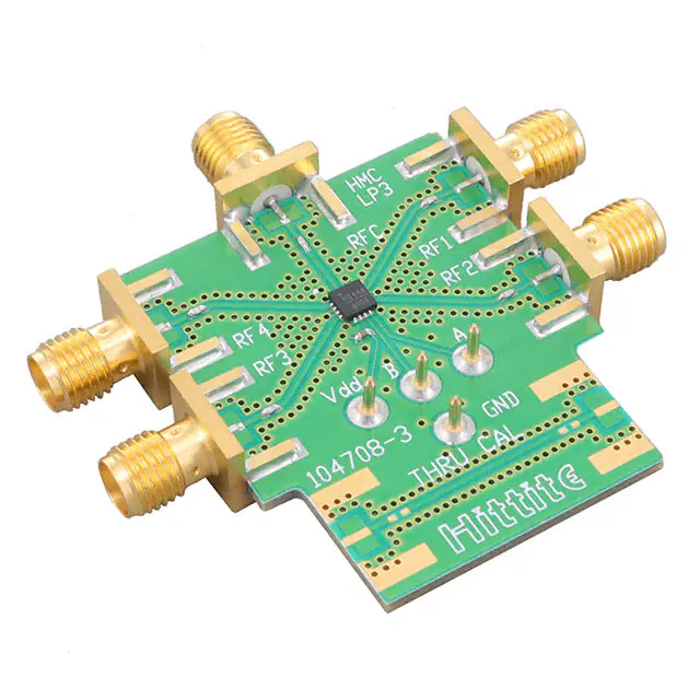
Figure 16 shows the layout of the EV1HMC344ALP3 evaluation
board with component placement. The power supply port is
connected to the VEE test point, J8. Control voltages, CTLA and
CTLB, are connected to the A and B test points, J9 and J10. The
ground reference is connected to the GND test point, J11. The
NIC pins are connected to the PCB ground to maximize
isolation. Use a 1 nF bypass capacitor on the supply trace, VEE,
to filter high frequency noise.
All RF and dc traces are routed on the top copper layer, and the
inner and bottom layers are grounded planes that provide a
solid ground for the RF transmission lines. The top dielectric
material is a 10 mil Rogers RO4350. The middle and bottom
dielectric materials provide mechanical strength. The overall board
thickness is approximately 62 mil allowing the Subminiature
Version A (SMA) launchers to be connected at the board edges.
The RF input and output ports (RFC, RF1 to RF4) connect through
50 Ω transmission lines to the SMA launchers, J1 to J5. These SMA
launchers are soldered onto the board. For connection to the RF
pins, R1 to R5 are populated with 0 Ω resistors. A through calibration line connects the unpopulated J6 and J7 launchers. This
transmission line estimates the loss of the PCB over the environmental conditions being evaluated, as shown in Figure 17.
Table 5 describes the evaluation board components.
The RF transmission lines were designed using a coplanar
waveguide (CPWG) model, with a trace width of 16 mil and a
ground clearance of 13 mil for a characteristic impedance of
50 Ω. For optimal RF and thermal grounding, arrange as many
plated through vias as possible around the transmission lines
and under the exposed pad of the package.
Component
R1 to R5
C6
R7, R8
J1 to J5
Default Value
0Ω
1 nF
Do not insert
Not applicable
J6, J7
Do not insert
J8 to J11
U1
PCB
Not applicable
HMC344ALP3E
104708-3
Figure 15 is the external interface circuit recommended for
transistor to transistor level (TTL) compatible control of the
negative voltage controlled switches.
Table 5. Evaluation Board Components
Rev. A | Page 9 of 11
Description
Resistors, R0402 package
Capacitor, C0402 package
Resistors, R0402 package
PCB mount and SMA
launchers
PCB mount and SMA
launchers
DC pins
SP4T switch
Evaluation PCB
�HMC344ALP3E
Data Sheet
R5
R1
R3
R2
14305-017
R4
Figure 16. EV1HMC344ALP3 Evaluation Board Component Placement
R5
J1
EPAD
J2
R1
RF4
R2
RF3
1
2
3
4
GND
RFC
GND
NIC
16
15
14
13
RFC
HMC344ALP3E
RF4
NIC
NIC
RF3
RF1
NIC
NIC
RF2
RF1
R4
RF2
J5
THRU CAL
R7
R8
J6
J7
A
J10
B
J9
VDD
J8
C6
Figure 17. EV1HMC344ALP3 Evaluation Board Schematic
Rev. A | Page 10 of 11
14305-018
5
6
7
8
GND
VEE
CTLB
CTLA
J3
J4
R3
12
11
10
9
�Data Sheet
HMC344ALP3E
OUTLINE DIMENSIONS
DETAIL A
(JEDEC 95)
3.10
3.00 SQ
2.90
0.50
BSC
13
PIN 1
INDIC ATOR AREA OPTIONS
(SEE DETAIL A)
16
1
12
1.70
1.60 SQ
1.50
EXPOSED
PAD
9
TOP VIEW
0.90
0.85
0.80
0.45
0.40
0.35
4
5
8
0.05 MAX
0.02 NOM
COPLANARITY
0.08
0.203 REF
PKG-004831
SEATING
PLANE
0.20 MIN
BOTTOM VIEW
FOR PROPER CONNECTION OF
THE EXPOSED PAD, REFER TO
THE PIN CONFIGURATION AND
FUNCTION DESCRIPTIONS
SECTION OF THIS DATA SHEET.
COMPLIANT TO JEDEC STANDARDS MO-220-VEED-4
11-22-2016-A
PIN 1
INDICATOR
0.30
0.25
0.20
Figure 18. 16-Lead Lead Frame Chip Scale Package [LFCSP]
3 mm × 3 mm Body and 0.85 mm Package Height
(CP-16-50)
Dimensions shown in millimeters
ORDERING GUIDE
Model1
HMC344ALP3E
HMC344ALP3ETR
EV1HMC344ALP3
1
Temperature Range
−40°C to +85°C
−40°C to +85°C
Package Description
16-Lead Lead Frame Chip Scale Package [LFCSP]
16-Lead Lead Frame Chip Scale Package [LFCSP]
Evaluation Board
All models are RoHS compliant parts.
©2017 Analog Devices, Inc. All rights reserved. Trademarks and
registered trademarks are the property of their respective owners.
D14305-0-12/17(A)
Rev. A | Page 11 of 11
Package Option
CP-16-50
CP-16-50
�


 工商网监
湘ICP备2023018690号
工商网监
湘ICP备2023018690号
