LT3433
High Voltage
Step-Up/Step-Down
DC/DC Converter
U
FEATURES
■
■
■
■
■
■
■
■
■
■
■
■
■
■
DESCRIPTIO
The LT®3433 is a 200kHz fixed-frequency current mode
switching regulator that provides both step-up and stepdown regulation using a single inductor. The IC operates
over a 4V to 60V input voltage range making it suitable for
use in various wide input voltage range applications such
as automotive electronics that must withstand both load
dump and cold crank conditions.
Automatic Step-Up and Step-Down Conversion
Uses a Single Inductor
Wide 4V to 60V Input Voltage Range
VOUT from 3.3V to 20V
Dual Internal 500mA Switches
100µA No-Load Quiescent Current
Low Current Shutdown
±1% Output Voltage Accuracy
200kHz Operating Frequency
Boosted Supply Pin to Saturate High Side Switch
Frequency Foldback Protection
Current Limit Foldback Protection
Current Limit Unaffected by Duty Cycle
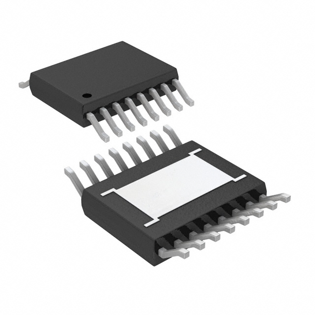
16-lead Thermally Enhanced TSSOP Package
Internal control circuitry monitors system conditions and
converts from single switch buck operation to dual switch
bridged operation when required, seamlessly changing
between step-down and step-up voltage conversion.
Optional Burst Mode® operation reduces no-load quiescent current to 100µA and maintains high efficiencies with
light loads.
U
APPLICATIO S
■
■
■
Current limit foldback and frequency foldback help prevent inductor current runaway during start-up. Programmable soft-start helps prevent output overshoot at start-up.
12V Automotive Systems
Wall Adapter Powered Systems
Battery Power Voltage Buffering
The LT3433 is available in a 16-lead thermally enhanced
TSSOP package.
, LTC and LT are registered trademarks of Linear Technology Corporation.
Burst Mode is a registered trademark of Linear Technology Corporation.
U.S. patent number: 5731694
U
TYPICAL APPLICATIO
Maximum Output
Current vs VIN
4V to 60V to 5V DC/DC Converter
with Burst Mode Operation
1N4148
VBST
SHDN
SWH
0.01µF
LT3433
B160A
100µH
B120A
SS
330pF
VOUT = 5V
0.1µF
2.2µF
VC
68k
SWL
VOUT
VOUT
+
47µF
1N4148
VBIAS
1nF
0.1µF
BURST_EN
90
500
309k
80
BUCK
VIN = 13.8V
400
70
EFFICIENCY (%)
VIN
MAXIMUM OUTPUT CURRENT (mA)
VIN
Efficiency
300
200
BRIDGED
60
50
VIN = 4V
40
100
30
VFB
SGND PGND
100k
3433 TA01
0
0
10
20
30
VIN (V)
40
50
60
3433 TA01c
20
0.1
1
10
100
OUTPUT CURRENT (mA)
1000
3433 TA01b
3433f
1
�LT3433
U
U
W W
W
Input Supply (VIN) .................................... –0.3V to 60V
Boosted Supply (VBST) .............. –0.3V to VSW_H + 30V
(VBST(MAX) = 80V)
Internal Supply (VBIAS) ............................. – 0.3V to 30V
SW_H Switch Voltage .................................. – 2V to 60V
SW_L Switch Voltage ............................... – 0.3V to 30V
Feedback Voltage (VFB) ............................... – 0.3V to 5V
Burst Enable Pin (VBURST_EN) ................... – 0.3V to 30V
Shutdown Pin (VSHDN) ............................. – 0.3V to 60V
Operating Junction Temperature Range (Note 5)
LT3433E (Note 6) ............................ – 40°C to 125°C
LT3433I ........................................... – 40°C to 125°C
Storage Temperature Range ................ – 65°C to 150°C
Lead Temperature (Soldering, 10 sec)................. 300°C
W
(Note 1)
U
ABSOLUTE MAXIMUM RATINGS
PACKAGE/ORDER INFORMATION
ORDER PART
NUMBER
TOP VIEW
SGND
1
16 SGND
VBST
2
15 SW_L
SW_H
3
14 PWRGND
VIN
4
13 VOUT
BURST_EN
5
12 VBIAS
VC
6
11 SHDN
VFB
7
10 SS
SGND
8
9
17
SGND
LT3433EFE
LT3433IFE
FE PART MARKING
3433EFE
3433IFE
FE PACKAGE
16-LEAD PLASTIC TSSOP
TJMAX = 125°C, θJA = 40°C/W, θJC = 10°C/W
EXPOSED PAD (PIN 17)
MUST BE SOLDERED TO SGND
Consult LTC Marketing for parts specified with wider operating temperature ranges.
ELECTRICAL CHARACTERISTICS
The ● denotes specifications that apply over the full operating temperature range, otherwise specifications are at TA = 25°C.
VIN = 13.8V, VFB = 1.25V, VOUT = 5V, VBURST_EN = 0V, VBST – VIN = 5V, unless otherwise noted.
SYMBOL
PARAMETER
VIN
Operating Voltage Range
VIN(UVLO)
Undervoltage Lockout
CONDITIONS
MIN
●
Enable Threshold
3.4
●
Undervoltage Lockout Hysteresis
VOUT
Operating Voltage Range
VBST
Operating Voltage Range
MAX
UNITS
60
V
3.95
V
160
mV
●
3.3
20
V
VBST < VSW_H + 20V
VBST – VSW_H
●
●
3.3
75
20
V
V
(Notes 2, 3)
VVC < 0.6V
VSHDN < 0.4V
●
●
●
580
100
10
940
190
25
µA
µA
µA
2.6
2.9
V
20
V
IVIN
Normal Operation
Burst Mode Operation
Shutdown
VBIAS
Internal Supply Output Voltage
●
Operating Voltage Range
●
IVBIAS
TYP
4
●
660
0.1
0.1
4.5
990
µA
µA
µA
mA
ISW = 500mA
●
0.8
1.2
Ω
Output Supply Switch On-Resistance
ISW = 500mA
●
0.6
1
Ω
Shutdown Pin Thresholds
Disable
Enable
●
●
1
V
V
Normal Operation
Burst Mode Operation
Shutdown
Short-Circuit Current Limit
VVC < 0.6V
VSHDN < 0.4V
RSWH(ON)
Boost Supply Switch On-Resistance
RSWL(ON)
VSHDN
0.4
IVBST/ISW
Boost Supply Switch Drive Current
High Side Switch On, ISW = 500mA
●
30
50
mA/A
IVOUT/ISW
Output Supply Switch Drive Current
Low Side Switch On, ISW = 500mA
●
30
50
mA/A
ILIM
Switch Current Limit
0.7
0.9
A
9
µA
Foldback Current Limit
ISS
Soft-Start Output Current
●
0.5
●
3
VFB = 0V
0.35
5
A
3433f
2
�LT3433
ELECTRICAL CHARACTERISTICS
The ● denotes specifications that apply over the full operating temperature range, otherwise specifications are at TA = 25°C.
VIN = 13.8V, VFB = 1.25V, VOUT = 5V, VBURST_EN = 0V, VBST – VIN = 5V, unless otherwise noted.
SYMBOL
PARAMETER
CONDITIONS
VFB
Feedback Reference Voltage
●
∆VFB
Feedback Reference Line Regulation
5.5V ≤ VIN ≤ 60V
IFB
VFB Pin Input Bias Current
●
gm
Error Amplifier Transconductance
●
AV
Error Amplifier Voltage Gain
ISW/VVC
Control Voltage to Switch Transconductance
fO
Operating Frequency
MIN
TYP
MAX
UNITS
1.224
1.215
1.231
1.238
1.245
V
V
0.002
0.01
%/V
●
200
35
100
nA
270
330
umhos
66
dB
0.6
VFB > 1V
185
170
●
Foldback Frequency
200
VFB = 0V
A/V
215
230
kHz
kHz
50
kHz
0.8
V
35
µA
VBURST_EN
Burst Enable Threshold
IBURST_EN
Input Bias Current
VBURST_EN ≥ 2V
tON(MIN)
Minimum Switch On Time
RL = 35Ω (Note 4)
●
250
450
ns
tOFF(MIN)
Minimum Switch Off Time
RL = 35Ω (Note 4)
●
500
800
ns
Note 1: Absolute Maximum Ratings are those values beyond which the life
of a device may be impaired.
Note 2: Supply current specification does not include switch drive
currents. Actual supply currents will be higher.
Note 3: “Normal Operation” supply current specification does not include
IBIAS currents. Powering the VBIAS pin externally reduces ICC supply
current.
Note 4: Minimum times are tested using the high side switch with a 35Ω
load to ground.
Note 5: This IC includes overtemperature protection that is intended to
protect the device during momentary overload conditions. Junction
temperature will exceed 125°C when overtemperature protection is active.
Continuous operation above the specified maximum operating junction
temperature may impair device reliability.
Note 6: The LT3433E is guaranteed to meet performance specifications
from 0°C to 125°C junction temperature. Specifications over the – 40°C to
125°C operating junction temperature range are assured by design,
characterization and correlation with statistical process controls. The
LT3433I is guaranteed over the full –40°C to 125°C operating junction
temperature range.
U W
TYPICAL PERFOR A CE CHARACTERISTICS
Maximum Output Current
vs VIN
VBIAS Output Voltage
vs Temperature
VOUT = 5V
TA = 25°C
TA = 25°C
400
300
200
BRIDGED
100
SEE TYPICAL APPLICATION
ON THE FIRST PAGE OF
THIS DATA SHEET
0
10
20
30
VIN (V)
40
50
60
3433 G11
590
2.6
IVIN (µA)
BUCK
VBIAS OUTPUT VOLTAGE (V)
MAXIMUM OUTPUT CURRENT (mA)
620
2.8
500
0
VIN Supply Current
vs VIN Supply Voltage
560
2.4
530
2.2
–50
500
0
50
TEMPERATURE (°C)
100
125
3433 G01
0
15
30
VIN (V)
45
60
3433 G02
3433f
3
�LT3433
U W
TYPICAL PERFOR A CE CHARACTERISTICS
Error Amp Reference
vs Temperature
Soft-Start Current vs Temperature
7.0
Switch Current Limit vs VFB
1.232
700
ERROR AMP REFERENCE (V)
ISS (µA)
6.0
5.5
5.0
SWITCH CURRENT LIMIT (mA)
TA = 25°C
6.5
1.231
1.230
1.229
4.5
4.0
–50
0
50
TEMPERATURE (°C)
100
125
1.228
–50
600
500
400
300
0
50
TEMPERATURE (°C)
100
3433 G03
125
0.2
0
0.6
0.4
VFB (V)
0.8
3433 G05
3433 G04
Oscillator Frequency
vs Temperature
Oscillator Frequency vs VFB
210
1.0
Current Limit vs Temperature
1.0
200
205
200
195
0.9
W/C HIGH
150
CURRENT LIMIT (A)
OSCILLATOR FREQUENCY (kHz)
OSCILLATOR FREQUENCY (kHz)
TA = 25°C
100
50
0.8
TYPICAL
0.7
0.6
W/C LOW
190
–50
0
50
TEMPERATURE (°C)
100
125
0
0.2
0
0.6
0.4
VFB (V)
0.8
3433 G06
50
25
0
75
TEMPERATURE (°C)
100
125
3433 G08
Maximum Output Supply Switch
Drive Current vs Output Supply
Voltage
70
TA = 25°C
TA = 25°C
65
IVOUT/ISW (mA/A)
65
IBST/ISW (mA/A)
1.0
3433 G07
Maximum Boost Supply Switch
Drive Current vs Boost Supply
Voltage
70
0.5
–50 –25
60
55
50
60
55
50
45
45
4
5
6
7
8
9
10
VBST – VSW_H (V)
11
12
4
5
6
7
8
9
10
11
12
VOUT (V)
3433 G09
3433 G10
3433f
4
�LT3433
U W
TYPICAL PERFOR A CE CHARACTERISTICS
VBST Supply Switch Drive Current
vs Temperature (ISW = 500mA)
Switch Resistance
vs Temperature (ISW = 500mA)
1.1
VOUT Supply Switch Drive Current
vs Temperature (ISW = 500mA)
40
40
37
37
RSWH
0.8
0.7
RSWL
IVOUT/ISW (mA/A)
0.9
IBST/ISW (mA/A)
SWITCH ON RESISTANCE (Ω)
1.0
34
31
34
31
0.6
28
0.5
0.4
–50 –25
50
25
75
0
TEMPERATURE (°C)
100
125
25
–50
28
–25
50
75
0
25
TEMPERATURE (°C)
3433 G12
100
125
3433 G13
25
–50
–25
50
75
0
25
TEMPERATURE (°C)
100
125
3433 G14
U
U
U
PI FU CTIO S
SGND (Pins 1, 8, 9, 16): Low Noise Ground Reference.
VBST (Pin 2): Boosted Switch Supply. This “boosted” supply rail is referenced to the SW_H pin. Supply voltage is
maintained by a bootstrap capacitor tied from the VBST pin
to the SW_H pin. A 1µF capacitor is generally adequate for
most applications.
The charge on the bootstrap capacitor is refreshed through
a diode, typically connected from the converter output
(VOUT), during the switch-off period. Minimum off-time
operation assures that the boost capacitor is refreshed each
switch cycle. The LT3433 supports operational VBST supply voltages up to 75V (absolute maximum) as referenced
to ground.
SW_H (Pin 3): Boosted Switch Output. This is the current
return for the boosted switch and corresponds to the emitter
of the switch transistor. The boosted switch shorts the
SW_H pin to the VIN supply when enabled. The drive circuitry for this switch is boosted above the VIN supply
through the VBST pin, allowing saturation of the switch for
maximum efficiency. The “ON” resistance of the boosted
switch is 0.8Ω.
VIN (Pin 4): Input Power Supply. This pin supplies power
to the boosted switch and corresponds to the collector of
the switch transistor.This pin also supplies power to most
of the IC’s internal circuitry if the VBIAS pin is not driven
externally. This supply will be subject to high switching
transient currents so this pin requires a high quality bypass
capacitor that meets whatever application-specific input
ripple current requirements exist.
BURST_EN (Pin 5): Burst Mode Enable/Disable. When
this pin is below 0.3V, Burst Mode operation is enabled.
Pin input bias current < 1µA when Burst Mode operation
is enabled. If Burst Mode operation is not desired, pulling
this pin above 2V will disable the burst function. When
Burst Mode operation is disabled, typical pin input current
= 35µA. BURST_EN should not be pulled above 20V. This
pin is typically shorted to SGND for Burst Mode function,
or connected to either VBIAS or VOUT to disable Burst Mode
operation.
VC (Pin 6): Error Amplifier Output. The voltage on the VC
pin corresponds to the maximum switch current per oscillator cycle. The error amplifier is typically configured as an
integrator circuit by connecting an RC network from this
pin to ground. This circuit typically creates the dominant
pole for the converter regulation feedback loop. Specific integrator characteristics can be configured to optimize transient response. See Applications Information.
3433f
5
�LT3433
U
U
U
PI FU CTIO S
VFB (Pin 7): Error Amplifier Inverting Input. The noninverting input of the error amplifier is connected to an internal
1.231V reference. The VFB pin is connected to a resistor
divider from the converter output. Values for the resistor
connected from VOUT to VFB (RFB1) and the resistor connected from VFB to ground (RFB2) can be calculated to program converter output voltage (VOUT) via the following
relation:
VOUT = 1.231 • (RFB1 + RFB2)/RFB2
The VFB pin input bias current is 35nA, so use of extremely
high value feedback resistors could cause a converter
output that is slightly higher than expected. Bias current
error at the output can be estimated as:
∆VOUT(BIAS) = 35nA • RFB1
The voltage on VFB also controls the LT3433 oscillator
frequency through a “frequency-foldback” function. When
the VFB pin voltage is below 0.8V, the oscillator runs slower
than the 200kHz typical operating frequency. The oscillator frequency slows with reduced voltage on the pin, down
to 50kHz when VFB = 0V.
The VFB pin voltage also controls switch current limit
through a “current-limit foldback” function. At VFB = 0V, the
maximum switch current is reduced to half of the normal
value. The current limit value increases linearly until VFB
reaches 0.6V when the normal maximum switch current
level is restored. The frequency and current-limit foldback
functions add robustness to short-circuit protection and
help prevent inductor current runaway during start-up.
SS (Pin 10): Soft Start. Connect a capacitor (CSS) from this
pin to ground. The output voltage of the LT3433 error
amplifier corresponds to the peak current sense amplifier
output detected before resetting the switch output(s). The
soft-start circuit forces the error amplifier output to a zero
peak current for start-up. A 5µA current is forced from the
SS pin onto an external capacitor. As the SS pin voltage
ramps up, so does the LT3433 internally sensed peak current limit. This forces the converter output current to ramp
from zero until normal output regulation is achieved. This
function reduces output overshoot on converter start-up.
The time from VSS = 0V to maximum available current can
be calculated given a capacitor CSS as:
tSS = (2.7 • 105)CSS or 0.27s/µF
SHDN (Pin 11): Shutdown. If the SHDN pin is externally
pulled below 0.5V, low current shutdown mode is initiated.
During shutdown mode, all internal functions are disabled,
and ICC is reduced to 10µA. This pin is intended to receive
a digital input, however, there is a small amount of input
hysteresis built into the SHDN circuit to help assure glitchfree mode switching. If shutdown is not desired, connect
the SHDN pin to VIN.
VBIAS (Pin 12): Internal Local Supply. Much of the LT3433
circuitry is powered from this supply, which is internally
regulated to 2.5V through an on-board linear regulator.
Current drive for this regulator is sourced from the VIN pin.
The VBIAS supply is short-circuit protected to 5mA.
The VBIAS supply only sources current, so forcing this pin
above the regulated voltage allows the use of external power
for much of the LT3433 circuitry. When using external drive,
this pin should be driven above 3V to assure the internal
supply is completely disabled. This pin is typically diodeconnected to the converter output to maximize conversion
efficiency. This pin must be bypassed with at least a 0.1µF
ceramic capacitor to SGND.
VOUT (Pin 13): Converter Output Pin. This pin voltage is
compared with the voltage on VIN internally to control
operation in single or 2-switch mode. When the ratios of
the two voltages are such that a >75% duty cycle is required
for regulation, the low side switch is enabled. Drive bias for
the low side switch is also derived directly from this pin.
PWRGND (Pin 14): High Current Ground Reference. This
is the current return for the low side switch and corresponds
to the emitter of the low side switch transistor.
SW_L (Pin 15): Ground Referenced Switch Output. This pin
is the collector of the low side switch transistor. The low
side switch shorts the SW_L pin to PWRGND when enabled.
The series impedance of the ground-referenced switch is
0.6Ω.
Exposed Pad (Pin 17): Exposed Pad must be soldered to
PCB ground for optimal thermal performance.
3433f
6
�LT3433
W
BLOCK DIAGRA
VBIAS
1.25V
BURST
CONTROL
CIRCUITS
BIAS
12
BURST_EN
5
VIN
4
SENSE
AMPLIFIER
VBST
2
COMPARATOR
BOOSTED
DRIVER
SW_H
3
SLOPE
COMP
OSCILLATOR 200kHz
FREQUENCY
CONTROL
MODE
CONTROL
SWITCH
CONTROL
LOGIC
SW_L
15
DRIVER
GND
VFB
14
7
ERROR
AMPLIFIER
30%
LOAD
1.231V
VC
+
Burst Mode
CONTROL
SHDN
6
11
SHUTDOWN
–
15%
LOAD
0.7V
SS
10
5µA
VOUT
SGND
1, 8, 9,16,17
13
3433 BD
VOUT
+
3433f
7
�LT3433
U
W
U U
APPLICATIO S I FOR ATIO
Overview
The LT3433 is a high input voltage range, step-up/stepdown DC/DC converter IC using a 200kHz constant frequency, current mode architecture. Dual internal switches
allow the full input voltage to be imposed across the
switched inductor, such that both step-up and step-down
modes of operation can be realized using the same single
inductor topology.
The LT3433 has provisions for high efficiency, low load
operation for battery-powered applications. Burst Mode
operation reduces average quiescent current to 100µA in
no load conditions. A low current shutdown mode can also
be activated, reducing total quiescent current to 10µA.
Much of the LT3433’s internal circuitry is biased from an
internal low voltage linear regulator. The output of this
regulator is brought out to the VBIAS pin, allowing bypassing of the internal regulator. The associated internal
circuitry can be powered directly from the output of the
converter, increasing overall converter efficiency. Using
externally derived power also eliminates the IC’s power
dissipation associated with the internal VIN to VBIAS
regulator.
Theory of Operation (See Block Diagram)
The LT3433 senses converter output voltage via the VFB
pin. The difference between the voltage on this pin and an
internal 1.231V reference is amplified to generate an error
voltage on the VC pin which is, in turn, used as a threshold
for the current sense comparator.
During normal operation, the LT3433 internal oscillator
runs at 200kHz. At the beginning of each oscillator cycle,
the switch drive is enabled. The switch drive stays enabled
until the sensed switch current exceeds the VC-derived
threshold for the current sense comparator and, in turn,
disables the switch driver. If the current comparator
threshold is not obtained for the entire oscillator cycle, the
switch driver is disabled at the end of the cycle for 250ns.
This minimum off-time mode of operation assures regeneration of the VBST bootstrapped supply.
If the converter input and output voltages are close
together, proper operation in normal buck configuration
would require high duty cycles. The LT3433 senses this
condition as requiring a duty cycle greater than 75%. If
such a condition exists, a second switch is enabled during
the switch on time, which acts to pull the output side of the
inductor to ground. This “bridged” operation allows voltage conversion to continue when VOUT approaches or
exceeds VIN.
Shutdown
The LT3433 incorporates a low current shutdown mode
where all IC functions are disabled and the VIN current is
reduced to 10µA. Pulling the SHDN pin down to 0.4V or
less activates shutdown mode.
Burst Mode Operation
The LT3433 employs low current Burst Mode functionality
to maximize efficiency during no load and low load conditions. Burst Mode function is disabled by shorting the
BURST_EN pin to either VBIAS or VOUT. Burst Mode
function is enabled by shorting BURST_EN to SGND.
In certain wide current range applications, the IC could
enter burst operation during normal load conditions. If the
additional output ripple and noise generated by Burst
Mode operation is not desired for normal operation,
BURST_EN can be biased using an external supply that is
disabled during a no-load condition. This enables Burst
Mode operation only when it is required. The BURST_EN
pin typically draws 35µA when Burst Mode operation is
disabled (VBURST_EN ≥ 2V) and will draw no more than
75µA with VBURST_EN = 2V.
When the required switch current, sensed via the VC pin
voltage, is below 30% of maximum, the Burst Mode
function is employed. When the voltage on VC drops below
the 30% load level, that level of sense current is latched
into the IC. If the output load requires less than this latched
current level, the converter will overdrive the output slightly
during each switch cycle. This overdrive condition forces
the voltage on the VC pin to continue to drop. When the
voltage on VC drops below the 15% load level, switching
is disabled, and the LT3433 shuts down most of its internal
circuitry, reducing quiescent current to 100µA. When the
voltage on the VC pin climbs back to 20% load level, the IC
returns to normal operation and switching resumes.
3433f
8
�LT3433
U
W
U U
APPLICATIO S I FOR ATIO
Antislope Compensation
Most current mode switching controllers use slope compensation to prevent current mode instability. The LT3433
is no exception. A slope compensation circuit imposes an
artificial ramp on the sensed current to increase the rising
slope as duty cycle increases. Unfortunately, this additional ramp corrupts the sensed current value, reducing
the achievable current limit value by the same amount as
the added ramp represents. As such, current limit is
typically reduced as duty cycles increase.
The LT3433 contains circuitry to eliminate the current limit
reduction associated with slope-compensation, or antislope compensation. As the slope compensation ramp is
added to the sensed current, a similar ramp is added to the
current limit threshold reference. The end result is that
current limit is not compromised so the LT3433 can
provide full power regardless of required duty cycle.
Mode Switching
The LT3433 switches between buck and buck/boost modes
of operation automatically. While in buck mode, if the
converter input voltage becomes close enough to the
output voltage to require a duty cycle greater than 75%,
the LT3433 enables a second switch which pulls the
output side of the inductor to ground during the switch-on
time. This “bridged” switching configuration allows voltage conversion to continue when VIN approaches or is less
than VOUT.
When the converter input voltage falls to where the duty
cycle required for continuous buck operation is greater
than 75%, the LT3433 enables its ground-referred switch,
changing the converter operation to a dual-switch bridged
configuration. Because the voltage available across the
switched inductor is greater while bridged, operational
duty cycle will decrease. Voltage drops associated with
external diodes and loss terms are estimated internally so
that required operating duty cycle can be calculated regardless of specific operating voltages.
In the simplest terms, a buck DC/DC converter switches
the VIN side of the inductor, while a boost converter
switches the VOUT side of the inductor. The LT3433
bridged topology merges the elements of buck and boost
topologies, providing switches on both sides of the inductor. Operating both switches simultaneously achieves
both step-up and step-down functionality.
Step-Down (VIN > VOUT)
VIN
SW
CIN
L
VOUT
D
COUT
Step-Up (VIN < VOUT)
L
VIN
CIN
D
SW
VOUT
COUT
Step-Up/Step-Down (VIN > VOUT or VIN < VOUT)
VIN
SW
CIN
L
D
D
SW
VOUT
COUT
3433 F01
Maximum duty cycle capability (DCMAX) gates the dropout
capabilities of a buck converter. As VIN – VOUT is reduced,
the required duty cycle increases until DCMAX is reached,
beyond which the converter loses regulation. With a
second switch bridging the switched inductor between VIN
and ground, the entire input voltage is imposed across the
inductor during the switch-on time, which subsequently
reduces the duty cycle required to maintain regulation.
Using this topology, regulation is maintained as VIN approaches or drops below VOUT.
Inductor Selection
The primary criterion for inductor value selection in LT3433
applications is the ripple current created in that inductor.
Design considerations for ripple current are converter
output capabilities in bridged mode, output voltage ripple
and the ability of the internal slope compensation waveform to prevent current mode instability.
3433f
9
�LT3433
U
W
U U
APPLICATIO S I FOR ATIO
The requirement for avoiding current mode instability is
that the rising slope of sensed inductor ripple current (S1)
is greater than the falling slope (S2). At duty cycles greater
than 50% this is not true. To avoid the instability condition,
a false signal is added to the sensed current with a slope
(SX) that is sufficient to prevent current mode instability,
or S1 + SX ≥ S2. This leads to the following relations:
SX ≥ S2(2DC – 1)/DC
If the forward voltages of a converter’s catch and pass
diodes are defined as VF1 and VF2, then:
S2 = (VOUT + VF1 + VF2)/L
Solving for L yields a relation for the minimum inductance
that will satisfy slope compensation requirements:
LMIN = (VOUT + VF1 + VF2)(2DC – 1)/(DC • SX)
The LT3433 maximizes available dynamic range using a
slope compensation generator that generates a continuously increasing slope as duty cycle increases. The slope
compensation waveform is calibrated at 80% duty cycle to
generate an equivalent slope of at least 0.05A/µs. The
equation for minimum inductance then reduces to:
Converter Capabilities
The output current capability of an LT3433 converter is
affected by a myriad of variables. The current in the
switches is limited by the LT3433. Switch current is
measured coming from the VIN supply, and does not
directly translate to a limitation in load current. This is
especially true during bridged mode operation when the
converter output current is discontinuous.
During bridged mode operation, the converter output
current is discontinuous, or only flowing to the output
while the switches are off (not to be confused with discontinuous switcher operation). As a result, the maximum
output current capability of the converter is reduced from
that during buck mode operation by a factor of roughly
1 – DC, not including additional losses. Most converter
losses are also a function of DC, so operational duty cycle
must be accurately determined to predict converter load
capabilities.
VIN
SW_H
LMIN = (VOUT + VF1 + VF2)(15e-6)
D1
LT3433
For example, with VOUT = 5V and using VF1 + VF2 = 1.1V
(cold):
SW_L
LMIN = (5 + 1.1)(15e-6) = 91.5µH
350
300
LMIN (µH)
250
200
150
100
4
6
8
10
12 14
VOUT (V)
16
D2
VOUT
3433 AI02
Slope Compensation Requirements
Typical Minimum Inductor Values vs VOUT
50
L
18
20
3433 AI01
Application variables:
VIN = Converter input supply voltage
VOUT = Converter programmed output voltage
VBST = Boosted supply voltage (VBST – VSWH)
DC = Operational duty cycle
fO = Switching frequency
IMAX = Peak switch current limit
∆IL = Inductor ripple current
ISW = Average switch current or peak switch current
less half the ripple current (IMAX – ∆IL/2)
RSWH = Boosted switch “on” resistance
RSWL = Grounded switch “on” resistance
L = Inductor value
3433f
10
�LT3433
U
W
U U
APPLICATIO S I FOR ATIO
RL = Inductor series resistance
∆BST = Boosted switch drive currents IVBST/ISW (in A/A)
∆OUT = Grounded switch drive currents IVOUT/ISW
(in A/A)
VF1 = Switch node catch diode forward voltage
VF2 = Pass diode forward voltage
IVIN = VIN quiescent input current
IIN = VIN switched current
IBIAS = VBIAS quiescent input current
RCESR = Output capacitor ESR
Operational duty cycle is a function of voltage imposed
across the switched inductance and switch on/off times.
Using the relation for change in current in an inductor:
δI = V • δt/L
and putting the application variables into the above relation yields:
δION(BRIDGED) = (DC/fO • L)[VIN – ISW • (RSWH + RSWL
+ RL)]
δION(BUCK) = (DC/fO • L)[VIN – VOUT – VF2 – ISW
• (RSWH + RL + RESR)]
δIOFF = [(1 – DC)/fO • L][VOUT + VF1 + VF2 – ISW
• (RL + RESR)]
Current conservation in an inductor dictates δION = δIOFF,
so plugging in the above relations and solving for DC yields:
DC(BRIDGED) = [VOUT + VF1 + VF2 – ISW • (RL + RESR)]/
[VIN – ISW • (RSWH + RSWL + 2RL + RESR) + VOUT +
VF1 + VF2 ]
DC(BUCK) = [VOUT + VF1 + VF2 – ISW • (RL + RESR)]/
[VIN – ISW • (RSWH + 2RL + 2RESR) + VF1]
In order to solve the above equations, inductor ripple
current (∆I) must be determined so ISW can be calculated.
∆I follows the relation:
∆I = (VOUT + VF1 + VF2 – ISW • RL)(1 – DC)/(L • fO)
As ∆I is a function of DC and vice-versa, the solution is
iterative. Seed ∆I and solve for DC. Using the resulting
value for DC, solve for ∆I. Use the resulting ∆I as the new
seed value and repeat. The calculated value for DC can be
used once the resulting ∆I is close (


 工商网监
湘ICP备2023018690号
工商网监
湘ICP备2023018690号
