PI6C2404A-1
12345678901234567890123456789012123456789012345678901234567890121234567890123456789012345678901212345678901234567890123456789012123456789012
12345678901234567890123456789012123456789012345678901234567890121234567890123456789012345678901212345678901234567890123456789012123456789012
Zero-Delay Clock Buffer
Features
Description
•
•
•
•
The PI6C2404A-1 is a PLL-based, zero-delay buffer, with the ability
to distribute four outputs of up to 133 MHz at 3.3V. Two banks of
two outputs exist, OUTA[1–2] and OUTB[1–2].
•
•
•
•
Maximum rated frequency: 133 MHz
Low cycle-to-cycle jitter
Input to output delay, less than 200ps
External feedback pin allows outputs to be synchronized
to the clock input
5V tolerant input*
Operates at 3.3V VDD
Test mode allows bypass of the PLL for system testing
purposes (e.g., IBIS measurements)
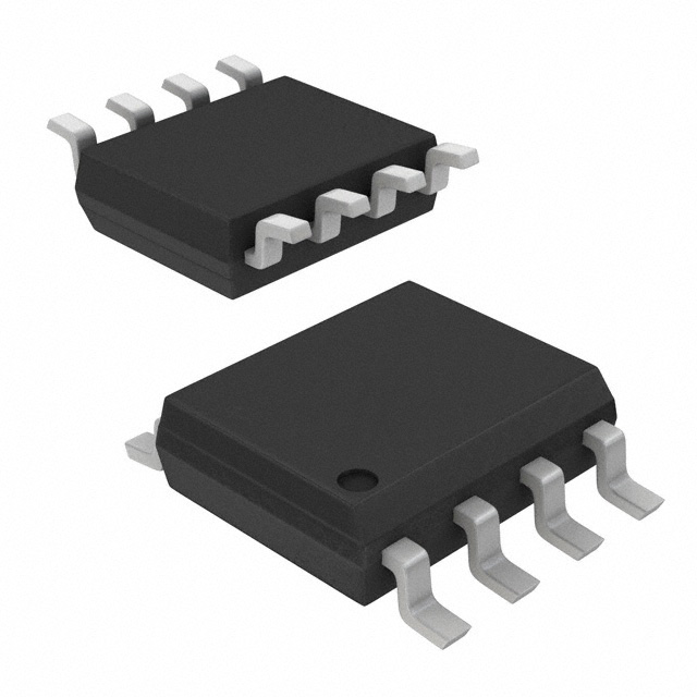
Space-saving Packaging (Pb-free and Green Available):
— 8-pin, 150-mil SOIC (W)
An external feedback pin is used to synchronize the outputs to the
input; the relationship between loading of this signal and the other
outputs determines the input-output delay.
The PI6C2404A-1 is characterized for both commercial and industrial
operation.
* FB_IN and CLKIN must reference the same voltage thresholds for the PLL to deliver zero delay skewing
Block Diagram
FB_IN
CLKIN
Pin Configuration
PLL
OUTA1
CLKIN
OUTA2
OUTA1
OUTB1
OUTA2
OUTB2
GND
1
8
2 8-Pin 7
W
6
3
4
5
FB_IN
VDD
OUTB2
OUTB1
Pin Description
Pin
1
Signal
D e s cription
C LK IN
Input clock reference frequency (weak pull- down)
O UTA[1- 2]
C lock output, Bank A
7
VDD
3.3V supply
4
GN D
Ground
O UTB[1- 2]
C lock output, Bank B
FB_IN
PLL feedback input
2, 3
5, 6
8
08-0298
1
PS8609B
11/12/08
�PI6C2404A-1
Zero-Delay Clock Buffer
12345678901234567890123456789012123456789012345678901234567890121234567890123456789012345678901212345678901234567890123456789012123456789012
12345678901234567890123456789012123456789012345678901234567890121234567890123456789012345678901212345678901234567890123456789012123456789012
Zero-Delay and Skew Control
CLKIN - Input to OUTA/OUTB Delay (ps)
CLKIN Input to Output Bank Delay vs. Difference in Loading between FB_IN pin and OUTA/OUTB pins
800
600
400
200
0
–200
–25
–20
–15
–10
0
–5
–400
5
10
15
20
25
PI6C2404A-1
–600
–800
–900
–1000
Output Load Difference: FB_IN Load - OUTA/OUTB Load (pF)
The relationship between loading of the FB_IN signal and other outputs determines the input-output delay. Zero delay is achieved when
all outputs, including feedback, are loaded equally.
Maximum Ratings
Supply Voltage to Ground Potential ............................................................................................................................. –0.5V to +7.0V
DC Input Voltage (Except CLKIN) ........................................................................................................................ –0.5V to VDD +0.5V
DC Input Voltage CLKIN ...................................................................................................................................................... –0.5 to 7V
Storage Temperature ................................................................................................................................................... –65ºC to +150ºC
Maximum Soldering Temperature (10 seconds) ........................................................................................................................... 260ºC
Junction Temperature .................................................................................................................................................................. 150ºC
Static Discharge Voltage (per MIL-STD-883, Method 3015) .................................................................................................... >2000V
Operating Conditions (VCC = 3.3V ±0.3V)
Parame te r
VDD
TA
CL
CIN
08-0298
De s cription
M in.
M a x.
Units
3 .0
3 .6
V
0
70
Industrial Operating Temperature
–4 0
85
Load Capacitance, below 100 MHz
⎯
30
Load Capacitance, from 100 MHz to 133 MHz
⎯
15
Input Capacitance
⎯
7.3
Supply Voltage
Commerical Operating Temperature
2
ºC
pF
PS8609B
11/12/08
�PI6C2404A-1
Zero-Delay Clock Buffer
12345678901234567890123456789012123456789012345678901234567890121234567890123456789012345678901212345678901234567890123456789012123456789012
12345678901234567890123456789012123456789012345678901234567890121234567890123456789012345678901212345678901234567890123456789012123456789012
DC Electrical Characteristics for Industrial Temperature Devices
Parame te r
De s cription
Te s t Conditions
M in.
M a x.
VIL
Input LOW Voltage
0.8
VIH
Input HIGH Voltage
IIL
Input LOW Current
VIN = 0V
50
IIH
Input HIGH Current
VIN = VDD
112
VO L
Output LOW Voltage
IO L = 8mA
0.4
VO H
Output HIGH Voltage
IO H = –8mA
IDD
Supply Current
Unloaded outputs 100 MHz, Select inputs at VDD or GND
54
Unloaded outputs 66 MHz, CLKIN
39
Unloaded outputs 33MHz, CLKIN
22
Units
V
2.0
μA
V
2.4
mA
AC Electrical Characteristics for Industrial Temperature Devices
Parame te rs
N ame
FO
O utput Frequency
tDC
Duty C ycle(1)
tR
Rise Time(1)
tF
tSK(O)
Fall Time(1)
O utput to O utput Skew
within same bank(1)
O UTA to O UTB
Te s t Conditions
30pF load
Measured at VDD/2, FOUT
很抱歉,暂时无法提供与“PI6C2404A-1WE”相匹配的价格&库存,您可以联系我们找货
免费人工找货