Order
Now
Product
Folder
Support &
Community
Tools &
Software
Technical
Documents
CSD18511KCS
SLPS548 – JULY 2017
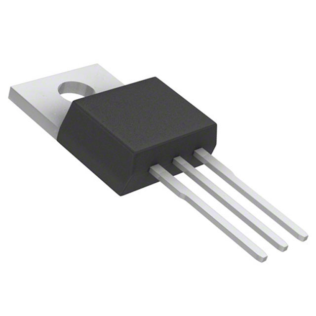
CSD18511KCS 40-V N-Channel NexFET™ Power MOSFET
1 Features
•
•
•
•
•
•
•
•
1
Product Summary
Low Qg and Qgd
Low RDS(ON)
Low-Thermal Resistance
Avalanche Rated
Lead-Free Terminal Plating
RoHS Compliant
Halogen Free
TO-220 Plastic Package
TA = 25°C
UNIT
Drain-to-Source Voltage
40
V
Qg
Gate Charge Total (10 V)
63.9
nC
Qgd
Gate Charge Gate-to-Drain
RDS(on)
Drain-to-Source On-Resistance
VGS(th)
Threshold Voltage
9.7
nC
VGS = 4.5 V
3.2
VGS = 10 V
2.1
mΩ
1.8
V
Device Information(1)
DEVICE
2 Applications
•
•
TYPICAL VALUE
VDS
MEDIA
CSD18511KCS
Secondary Side Synchronous Rectifier
Motor Control
Tube
QTY
PACKAGE
SHIP
50
TO-220
Plastic Package
Tube
(1) For all available packages, see the orderable addendum at
the end of the data sheet.
3 Description
This 40-V, 2.1-mΩ, TO-220 NexFET™ power
MOSFET is designed to minimize losses in power
conversion applications.
Drain (Pin 2)
Absolute Maximum Ratings
TA = 25°C
VALUE
UNIT
VDS
Drain-to-Source Voltage
40
V
VGS
Gate-to-Source Voltage
±20
V
Continuous Drain Current (Package Limited)
110
Continuous Drain Current (Silicon Limited),
TC = 25°C
194
Continuous Drain Current (Silicon Limited),
TC = 100°C
137
IDM
Pulsed Drain Current(1)
400
A
PD
Power Dissipation
188
W
TJ,
Tstg
Operating Junction,
Storage Temperature
–55 to 175
°C
EAS
Avalanche Energy, Single Pulse
ID = 56 A, L = 0.1 mH, RG = 25 Ω
156
mJ
ID
Gate
(Pin 1)
Source (Pin 3)
A
(1) Max RθJC = 0.8°C/W, pulse duration ≤ 100 μs, duty cycle ≤
1%.
RDS(on) vs VGS
Gate Charge
10
TC = 25° C, I D = 100 A
TC = 125° C, I D = 100 A
9
VGS - Gate-to-Source Voltage (V)
RDS(on) - On-State Resistance (m:)
10
8
7
6
5
4
3
2
1
0
ID = 100 A
9 VDS = 20 V
8
7
6
5
4
3
2
1
0
0
2
4
6
8
10
12
14
16
VGS - Gate-to-Source Voltage (V)
18
20
D007
0
10
20
30
40
50
Qg - Gate Charge (nC)
60
70
D004
1
An IMPORTANT NOTICE at the end of this data sheet addresses availability, warranty, changes, use in safety-critical applications,
intellectual property matters and other important disclaimers. PRODUCTION DATA.
�CSD18511KCS
SLPS548 – JULY 2017
www.ti.com
Table of Contents
1
2
3
4
5
Features ..................................................................
Applications ...........................................................
Description .............................................................
Revision History.....................................................
Specifications.........................................................
1
1
1
2
3
6
Device and Documentation Support.................... 7
6.1
6.2
6.3
6.4
6.5
5.1 Electrical Characteristics........................................... 3
5.2 Thermal Information .................................................. 3
5.3 Typical MOSFET Characteristics.............................. 4
7
Receiving Notification of Documentation Updates....
Community Resources..............................................
Trademarks ...............................................................
Electrostatic Discharge Caution ................................
Glossary ....................................................................
7
7
7
7
7
Mechanical, Packaging, and Orderable
Information ............................................................. 8
7.1 KCS Package Dimensions........................................ 8
4 Revision History
2
DATE
REVISION
NOTES
July 2017
*
Initial release.
Submit Documentation Feedback
Copyright © 2017, Texas Instruments Incorporated
Product Folder Links: CSD18511KCS
�CSD18511KCS
www.ti.com
SLPS548 – JULY 2017
5 Specifications
5.1 Electrical Characteristics
TA = 25°C (unless otherwise stated)
PARAMETER
TEST CONDITIONS
MIN
TYP
MAX
UNIT
STATIC CHARACTERISTICS
BVDSS
Drain-to-source voltage
VGS = 0 V, ID = 250 μA
IDSS
Drain-to-source leakage current
VGS = 0 V, VDS = 32 V
1
μA
IGSS
Gate-to-source leakage current
VDS = 0 V, VGS = 20 V
100
nA
VGS(th)
Gate-to-source threshold voltage
VDS = VGS, ID = 250 μA
V
RDS(on)
Drain-to-source on-resistance
gfs
Transconductance
40
1.5
V
1.8
2.4
VGS = 4.5 V, ID = 100 A
3.2
4.2
VGS = 10 V, ID = 100 A
2.1
2.6
VDS = 4 V, ID = 100 A
249
mΩ
S
DYNAMIC CHARACTERISTICS
Ciss
Input capacitance
Coss
Output capacitance
4570
5940
pF
454
591
pF
Crss
RG
Reverse transfer capacitance
235
306
pF
Series gate resistance
0.9
1.8
Qg
Gate charge total (4.5 V)
31
nC
Qg
Gate charge total (10 V)
Qgd
Gate charge gate-to-drain
Qgs
Gate charge gate-to-source
Qg(th)
Gate charge at Vth
Qoss
Output charge
td(on)
VGS = 0 V, VDS = 20 V, ƒ = 1 MHz
VDS = 20 V, ID = 100 A
Ω
64
nC
9.7
nC
17.9
nC
7.4
nC
20.7
nC
Turnon delay time
8
ns
tr
Rise time
6
ns
td(off)
Turnoff delay time
17
ns
tf
Fall time
3
ns
VDS = 20 V, VGS = 0 V
VDS = 20 V, VGS = 10 V,
IDS = 100 A, RG = 0 Ω
DIODE CHARACTERISTICS
VSD
Diode forward voltage
Qrr
Reverse recovery charge
trr
Reverse recovery time
ISD = 100 A, VGS = 0 V
0.9
VDS= 20 V, IF = 100 A,
di/dt = 300 A/μs
62
1.0
nC
V
31
ns
5.2 Thermal Information
TA = 25°C (unless otherwise stated)
MAX
UNIT
RθJC
Junction-to-case thermal resistance
THERMAL METRIC
MIN
TYP
0.8
°C/W
RθJA
Junction-to-ambient thermal resistance
62
°C/W
Submit Documentation Feedback
Copyright © 2017, Texas Instruments Incorporated
Product Folder Links: CSD18511KCS
3
�CSD18511KCS
SLPS548 – JULY 2017
www.ti.com
5.3 Typical MOSFET Characteristics
TA = 25°C (unless otherwise stated)
200
200
175
175
IDS - Drain-to-Source Current (A)
IDS - Drain-to-Source Current (A)
Figure 1. Transient Thermal Impedance
150
125
100
75
50
VGS = 4.5 V
VGS = 8 V
VGS = 10 V
25
0
TC = 125° C
TC = 25° C
TC = -55° C
150
125
100
75
50
25
0
0
0.1
0.2
0.3 0.4 0.5 0.6 0.7 0.8
VDS - Drain-to-Source Voltage (V)
0.9
1
1
1.5
D002
2
2.5
3
3.5
4
VGS - Gate-to-Source Voltage (V)
4.5
5
D003
VDS = 5 V
Figure 2. Saturation Characteristics
4
Submit Documentation Feedback
Figure 3. Transfer Characteristics
Copyright © 2017, Texas Instruments Incorporated
Product Folder Links: CSD18511KCS
�CSD18511KCS
www.ti.com
SLPS548 – JULY 2017
Typical MOSFET Characteristics (continued)
TA = 25°C (unless otherwise stated)
10000
9
8
C - Capacitance (pF)
VGS - Gate-to-Source Voltage (V)
10
7
6
5
4
3
Ciss = Cgd + Cgs
Coss = Cds + Cgd
Crss = Cgd
1000
2
1
100
0
0
10
20
30
40
50
Qg - Gate Charge (nC)
VDS = 20 V
60
0
70
10
20
30
VDS - Drain-to-Source Voltage (V)
D004
Figure 5. Capacitance
2.6
10
2.4
9
RDS(on) - On-State Resistance (m:)
VGS(th) - Threshold Voltage (V)
D005
ID = 100 A
Figure 4. Gate Charge
2.2
2
1.8
1.6
1.4
1.2
1
0.8
0.6
-75
40
TC = 25° C, I D = 100 A
TC = 125° C, I D = 100 A
8
7
6
5
4
3
2
1
0
-50
-25
0
0
25 50 75 100 125 150 175 200
TC - Case Temperature (qC)
D006
2
4
6
8
10
12
14
16
VGS - Gate-to-Source Voltage (V)
18
20
D007
ID = 250 µA
Figure 7. On-State Resistance vs Gate-to-Source Voltage
Figure 6. Threshold Voltage vs Temperature
100
2
VGS = 4.5 V
VGS = 10 V
ISD - Source-to-Drain Current (A)
Normalized On-State Resistance
2.2
1.8
1.6
1.4
1.2
1
0.8
0.6
0.4
-75
TC = 25qC
TC = 125qC
10
1
0.1
0.01
0.001
0.0001
-50
-25
0
25 50 75 100 125 150 175 200
TC - Case Temperature (° C)
D008
0
0.2
0.4
0.6
0.8
VSD - Source-to-Drain Voltage (V)
1
D009
ID = 100 A
Figure 8. Normalized On-State Resistance vs Temperature
Figure 9. Typical Diode Forward Voltage
Submit Documentation Feedback
Copyright © 2017, Texas Instruments Incorporated
Product Folder Links: CSD18511KCS
5
�CSD18511KCS
SLPS548 – JULY 2017
www.ti.com
Typical MOSFET Characteristics (continued)
TA = 25°C (unless otherwise stated)
100
IAV - Peak Avalanche Current (A)
IDS - Drain-to-Source Current (A)
1000
100
10
1
DC
10 ms
0.1
0.1
1 ms
100 µs
10 µs
1
10
VDS - Drain-to-Source Voltage (V)
100
10
TC = 25q C
TC = 125q C
1
0.01
0.1
TAV - Time in Avalanche (ms)
D010
1
D011
Single pulse, max RθJC = 0.8°C/W
Figure 10. Maximum Safe Operating Area
Figure 11. Single Pulse Unclamped Inductive Switching
IDS - Drain-to-Source Current (A)
150
125
100
75
50
25
0
-50
-25
0
25
50
75 100 125
TC - Case Temperature (qC)
150
175
200
D012
Max RθJC = 0.8°C/W
Figure 12. Maximum Drain Current vs Temperature
6
Submit Documentation Feedback
Copyright © 2017, Texas Instruments Incorporated
Product Folder Links: CSD18511KCS
�CSD18511KCS
www.ti.com
SLPS548 – JULY 2017
6 Device and Documentation Support
6.1 Receiving Notification of Documentation Updates
To receive notification of documentation updates, navigate to the device product folder on ti.com. In the upper
right corner, click on Alert me to register and receive a weekly digest of any product information that has
changed. For change details, review the revision history included in any revised document.
6.2 Community Resources
The following links connect to TI community resources. Linked contents are provided "AS IS" by the respective
contributors. They do not constitute TI specifications and do not necessarily reflect TI's views; see TI's Terms of
Use.
TI E2E™ Online Community TI's Engineer-to-Engineer (E2E) Community. Created to foster collaboration
among engineers. At e2e.ti.com, you can ask questions, share knowledge, explore ideas and help
solve problems with fellow engineers.
Design Support TI's Design Support Quickly find helpful E2E forums along with design support tools and
contact information for technical support.
6.3 Trademarks
NexFET, E2E are trademarks of Texas Instruments.
All other trademarks are the property of their respective owners.
6.4 Electrostatic Discharge Caution
These devices have limited built-in ESD protection. The leads should be shorted together or the device placed in conductive foam
during storage or handling to prevent electrostatic damage to the MOS gates.
6.5 Glossary
SLYZ022 — TI Glossary.
This glossary lists and explains terms, acronyms, and definitions.
Submit Documentation Feedback
Copyright © 2017, Texas Instruments Incorporated
Product Folder Links: CSD18511KCS
7
�CSD18511KCS
SLPS548 – JULY 2017
www.ti.com
7 Mechanical, Packaging, and Orderable Information
The following pages include mechanical, packaging, and orderable information. This information is the most
current data available for the designated devices. This data is subject to change without notice and revision of
this document. For browser-based versions of this data sheet, refer to the left-hand navigation.
7.1 KCS Package Dimensions
Table 1. Pin Configuration
8
POSITION
DESIGNATION
Pin 1
Gate
Pin 2 / Tab
Drain
Pin 3
Source
Submit Documentation Feedback
Copyright © 2017, Texas Instruments Incorporated
Product Folder Links: CSD18511KCS
�IMPORTANT NOTICE
Texas Instruments Incorporated (TI) reserves the right to make corrections, enhancements, improvements and other changes to its
semiconductor products and services per JESD46, latest issue, and to discontinue any product or service per JESD48, latest issue. Buyers
should obtain the latest relevant information before placing orders and should verify that such information is current and complete.
TI’s published terms of sale for semiconductor products (http://www.ti.com/sc/docs/stdterms.htm) apply to the sale of packaged integrated
circuit products that TI has qualified and released to market. Additional terms may apply to the use or sale of other types of TI products and
services.
Reproduction of significant portions of TI information in TI data sheets is permissible only if reproduction is without alteration and is
accompanied by all associated warranties, conditions, limitations, and notices. TI is not responsible or liable for such reproduced
documentation. Information of third parties may be subject to additional restrictions. Resale of TI products or services with statements
different from or beyond the parameters stated by TI for that product or service voids all express and any implied warranties for the
associated TI product or service and is an unfair and deceptive business practice. TI is not responsible or liable for any such statements.
Buyers and others who are developing systems that incorporate TI products (collectively, “Designers”) understand and agree that Designers
remain responsible for using their independent analysis, evaluation and judgment in designing their applications and that Designers have
full and exclusive responsibility to assure the safety of Designers' applications and compliance of their applications (and of all TI products
used in or for Designers’ applications) with all applicable regulations, laws and other applicable requirements. Designer represents that, with
respect to their applications, Designer has all the necessary expertise to create and implement safeguards that (1) anticipate dangerous
consequences of failures, (2) monitor failures and their consequences, and (3) lessen the likelihood of failures that might cause harm and
take appropriate actions. Designer agrees that prior to using or distributing any applications that include TI products, Designer will
thoroughly test such applications and the functionality of such TI products as used in such applications.
TI’s provision of technical, application or other design advice, quality characterization, reliability data or other services or information,
including, but not limited to, reference designs and materials relating to evaluation modules, (collectively, “TI Resources”) are intended to
assist designers who are developing applications that incorporate TI products; by downloading, accessing or using TI Resources in any
way, Designer (individually or, if Designer is acting on behalf of a company, Designer’s company) agrees to use any particular TI Resource
solely for this purpose and subject to the terms of this Notice.
TI’s provision of TI Resources does not expand or otherwise alter TI’s applicable published warranties or warranty disclaimers for TI
products, and no additional obligations or liabilities arise from TI providing such TI Resources. TI reserves the right to make corrections,
enhancements, improvements and other changes to its TI Resources. TI has not conducted any testing other than that specifically
described in the published documentation for a particular TI Resource.
Designer is authorized to use, copy and modify any individual TI Resource only in connection with the development of applications that
include the TI product(s) identified in such TI Resource. NO OTHER LICENSE, EXPRESS OR IMPLIED, BY ESTOPPEL OR OTHERWISE
TO ANY OTHER TI INTELLECTUAL PROPERTY RIGHT, AND NO LICENSE TO ANY TECHNOLOGY OR INTELLECTUAL PROPERTY
RIGHT OF TI OR ANY THIRD PARTY IS GRANTED HEREIN, including but not limited to any patent right, copyright, mask work right, or
other intellectual property right relating to any combination, machine, or process in which TI products or services are used. Information
regarding or referencing third-party products or services does not constitute a license to use such products or services, or a warranty or
endorsement thereof. Use of TI Resources may require a license from a third party under the patents or other intellectual property of the
third party, or a license from TI under the patents or other intellectual property of TI.
TI RESOURCES ARE PROVIDED “AS IS” AND WITH ALL FAULTS. TI DISCLAIMS ALL OTHER WARRANTIES OR
REPRESENTATIONS, EXPRESS OR IMPLIED, REGARDING RESOURCES OR USE THEREOF, INCLUDING BUT NOT LIMITED TO
ACCURACY OR COMPLETENESS, TITLE, ANY EPIDEMIC FAILURE WARRANTY AND ANY IMPLIED WARRANTIES OF
MERCHANTABILITY, FITNESS FOR A PARTICULAR PURPOSE, AND NON-INFRINGEMENT OF ANY THIRD PARTY INTELLECTUAL
PROPERTY RIGHTS. TI SHALL NOT BE LIABLE FOR AND SHALL NOT DEFEND OR INDEMNIFY DESIGNER AGAINST ANY CLAIM,
INCLUDING BUT NOT LIMITED TO ANY INFRINGEMENT CLAIM THAT RELATES TO OR IS BASED ON ANY COMBINATION OF
PRODUCTS EVEN IF DESCRIBED IN TI RESOURCES OR OTHERWISE. IN NO EVENT SHALL TI BE LIABLE FOR ANY ACTUAL,
DIRECT, SPECIAL, COLLATERAL, INDIRECT, PUNITIVE, INCIDENTAL, CONSEQUENTIAL OR EXEMPLARY DAMAGES IN
CONNECTION WITH OR ARISING OUT OF TI RESOURCES OR USE THEREOF, AND REGARDLESS OF WHETHER TI HAS BEEN
ADVISED OF THE POSSIBILITY OF SUCH DAMAGES.
Unless TI has explicitly designated an individual product as meeting the requirements of a particular industry standard (e.g., ISO/TS 16949
and ISO 26262), TI is not responsible for any failure to meet such industry standard requirements.
Where TI specifically promotes products as facilitating functional safety or as compliant with industry functional safety standards, such
products are intended to help enable customers to design and create their own applications that meet applicable functional safety standards
and requirements. Using products in an application does not by itself establish any safety features in the application. Designers must
ensure compliance with safety-related requirements and standards applicable to their applications. Designer may not use any TI products in
life-critical medical equipment unless authorized officers of the parties have executed a special contract specifically governing such use.
Life-critical medical equipment is medical equipment where failure of such equipment would cause serious bodily injury or death (e.g., life
support, pacemakers, defibrillators, heart pumps, neurostimulators, and implantables). Such equipment includes, without limitation, all
medical devices identified by the U.S. Food and Drug Administration as Class III devices and equivalent classifications outside the U.S.
TI may expressly designate certain products as completing a particular qualification (e.g., Q100, Military Grade, or Enhanced Product).
Designers agree that it has the necessary expertise to select the product with the appropriate qualification designation for their applications
and that proper product selection is at Designers’ own risk. Designers are solely responsible for compliance with all legal and regulatory
requirements in connection with such selection.
Designer will fully indemnify TI and its representatives against any damages, costs, losses, and/or liabilities arising out of Designer’s noncompliance with the terms and provisions of this Notice.
Mailing Address: Texas Instruments, Post Office Box 655303, Dallas, Texas 75265
Copyright © 2018, Texas Instruments Incorporated
�