User's Guide
SLLU210C – October 2014 – Revised September 2019
DRV8848EVM Hardware and GUI User Guide
This document is provided with the DRV8848 customer evaluation module (EVM) as a supplement to the
DRV8848 Dual H-Bridge Motor Driver data sheet. This document describes the hardware implementation
of the EVM.
1
2
3
Contents
DRV8848 EVM Overview ................................................................................................... 3
1.1
Connectors .......................................................................................................... 3
1.2
Configuration Jumpers ............................................................................................. 4
1.3
Jumpers .............................................................................................................. 4
1.4
Motor Output ........................................................................................................ 4
GUI Software Installation ................................................................................................... 4
2.1
System Requirements .............................................................................................. 4
2.2
Installation Procedure .............................................................................................. 4
DRV8848 EVM GUI ........................................................................................................ 10
3.1
Operate the EVM .................................................................................................. 10
3.2
Normal Mode Operation .......................................................................................... 11
3.3
Parallel Mode Operation.......................................................................................... 11
3.4
Stepper Mode Operation ......................................................................................... 12
3.5
Menu Options ...................................................................................................... 12
List of Figures
1
DRV8848 EVM ............................................................................................................... 3
2
Connections .................................................................................................................. 3
3
GUIComposerApp-0.1.0.setup-win_2.0.4................................................................................. 5
4
Installation Initialization
5
License Agreement .......................................................................................................... 7
6
Installation Directory ......................................................................................................... 7
7
Installation in Progress ...................................................................................................... 8
8
Setup Completion ............................................................................................................ 9
9
Readme Window............................................................................................................. 9
10
DRV8848 EVM GUI ........................................................................................................ 10
11
Normal Mode Operation ................................................................................................... 11
12
Parallel Mode Operation
13
Stepper Mode Operation .................................................................................................. 12
14
File Menu .................................................................................................................... 13
15
Edit Menu
16
Options Menu ............................................................................................................... 14
17
Help Menu................................................................................................................... 14
18
About Page .................................................................................................................. 15
.....................................................................................................
..................................................................................................
...................................................................................................................
6
11
13
List of Tables
1
J5 Header Connections ..................................................................................................... 4
SLLU210C – October 2014 – Revised September 2019
Submit Documentation Feedback
DRV8848EVM Hardware and GUI User Guide
Copyright © 2014–2019, Texas Instruments Incorporated
1
�www.ti.com
Trademarks
MSP430 is a trademark of Texas Instruments.
All other trademarks are the property of their respective owners.
2
DRV8848EVM Hardware and GUI User Guide
SLLU210C – October 2014 – Revised September 2019
Submit Documentation Feedback
Copyright © 2014–2019, Texas Instruments Incorporated
�DRV8848 EVM Overview
www.ti.com
1
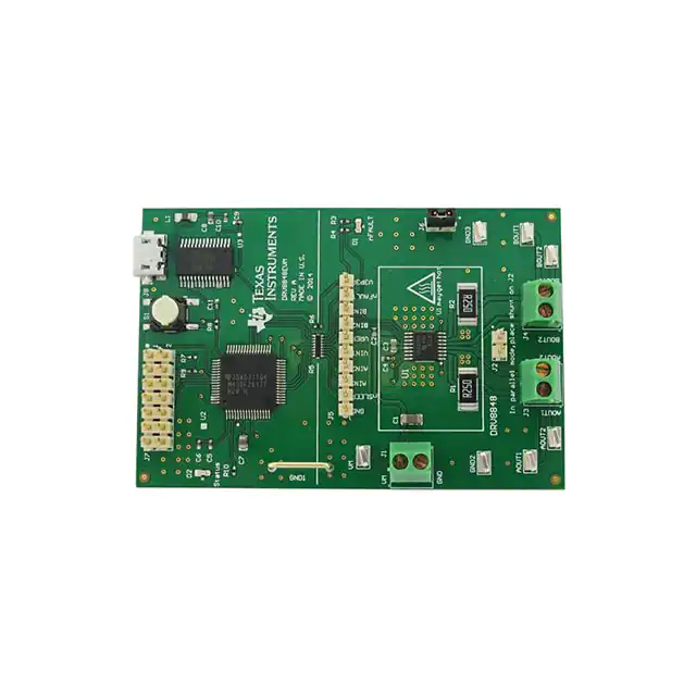
DRV8848 EVM Overview
Figure 1. DRV8848 EVM
The DRV8848 customer EVM is a platform revolving around the DRV8848, a low voltage dual H-bridge
driver and highly-configurable power stage. This device has been optimized to control one or two brushed
DC motors, or a stepper motor. The DRV8848 can also be configured to drive a single brushed DC motor
using both output stages in parallel mode to increase the drive current.
The EVM houses an MSP430 microcontroller and an USB interface chip. The USB chip allows for serial
communications from a PC where a Microsoft® Windows® application is used to schedule serial
commands. These commands can be used to control each of the device’s signals, and drive the motors at
the desired rate.
The microcontroller firmware outputs the control signals and PWM signals to move the motor. The
firmware also monitors the nFAULT signal to alert the GUI that a FAULT has occurred. This document
details the operation of the EVM, as well as the hardware reconfigurability of the evaluation module.
1.1
Connectors
The DRV8848EVM offers access to the VM (motor voltage) power rail via a terminal block (J1). A set of
test clips in parallel with the terminal block allows for the monitoring of the input power rail. The VM must
be applied according to the recommended parameters in the DRV8848 Dual H-Bridge Motor Driver data
sheet.
NOTE: VDD for the microcontroller is derived from the micro USB connector.
Figure 2. Connections
SLLU210C – October 2014 – Revised September 2019
Submit Documentation Feedback
DRV8848EVM Hardware and GUI User Guide
Copyright © 2014–2019, Texas Instruments Incorporated
3
�DRV8848 EVM Overview
1.2
www.ti.com
Configuration Jumpers
A 0.100-inch pitch header connector (J5) is used to provide access to every device signal in the external
event control of the DRV8848 if desired. To disconnect the internal MSP430™ microcontroller, remove
resistor pack R5 and resistor R6. Table 1 lists the connections available on the J5 header. Each header
pin is labeled on the evaluation module and matches the pin of the DRV8848.
Table 1. J5 Header Connections
1.3
Header Label
Description
GND
Ground
nSLEEP
Sleep mode input
AIN1
AIN1 input
AIN2
AIN2 input
VINT
Internal supply voltage of the DRV8848
VREF
Scale voltage to set IFS
BIN2
BIN2 input
BIN1
BIN1 input
nFAULT
Fault indication from DRV8848
V3P3R
3.3-V supply from FTDI FT232RL
Jumpers
There are two jumpers on the DRV8848EVM module. J2 is used to connect the two sense resistors in
parallel. This allows the use of one brushed motor at higher current. J6 is used to hold the shunt when not
in use.
1.4
Motor Output
Two motor connectors are provided. Connectors J3 and J4 are available as shown in Figure 2.
2
GUI Software Installation
The following section explains the location and the procedure for installing the software properly.
NOTE: Make sure that no USB connections are made to the EVM until the installation is complete.
The installer also installs the GUI Composer V2 Runtime along with the GUI installation.
2.1
System Requirements
•
•
•
2.2
Supported OS – Windows 7 (32 Bit, 64 Bit)
Recommended RAM memory - 4 GB or higher
Recommended CPU Operating Speed – 3.3 GHz or higher
Installation Procedure
The following procedure will help you install the DRV8848 GUI.
Step 1. Double click on the GUIComposerApp-0.1.0.setup-win_2.0.4 as shown in Figure 3.
4
DRV8848EVM Hardware and GUI User Guide
SLLU210C – October 2014 – Revised September 2019
Submit Documentation Feedback
Copyright © 2014–2019, Texas Instruments Incorporated
�GUI Software Installation
www.ti.com
Figure 3. GUIComposerApp-0.1.0.setup-win_2.0.4
A screen shown in Figure 4 will appear indicating installer initialization. Click Next button.
SLLU210C – October 2014 – Revised September 2019
Submit Documentation Feedback
DRV8848EVM Hardware and GUI User Guide
Copyright © 2014–2019, Texas Instruments Incorporated
5
�GUI Software Installation
www.ti.com
Figure 4. Installation Initialization
Step 2.
6
The License Agreements will appear.
• A Screen as shown in Figure 5 will appear, displaying the license agreement of DRV8848
EVM GUI. Please read through the agreement carefully and enable the “I Accept the
License Agreement” radio button and press the Next button.
DRV8848EVM Hardware and GUI User Guide
SLLU210C – October 2014 – Revised September 2019
Submit Documentation Feedback
Copyright © 2014–2019, Texas Instruments Incorporated
�GUI Software Installation
www.ti.com
Figure 5. License Agreement
Step 3.
Set the default directory for the GUI installation and press the Next button.
Figure 6. Installation Directory
SLLU210C – October 2014 – Revised September 2019
Submit Documentation Feedback
DRV8848EVM Hardware and GUI User Guide
Copyright © 2014–2019, Texas Instruments Incorporated
7
�GUI Software Installation
www.ti.com
NOTE: It is highly recommended to keep the default values as provided in the installer.
Step 4.
Step 5.
Step 6.
At this point, a few options may appear. If the GUI Composer Runtime v.2.0.6 has not been
previously installed, select Install from File radio button and download the runtime from the
following link, GC Runtime v2.0.6. Click the Search button to the right of the text box next to
Install from File and select the downloaded runtime v.2.0.6 file. Click Next to continue.
The installer will begin self-extraction of GUI Composer component and proceed with the
installation.
After the self-extraction of GUI Composer component, the installer will proceed with the
installation as shown in Figure 7.
Figure 7. Installation in Progress
Step 7.
8
When the installation is complete, the final page will be displayed.
DRV8848EVM Hardware and GUI User Guide
SLLU210C – October 2014 – Revised September 2019
Submit Documentation Feedback
Copyright © 2014–2019, Texas Instruments Incorporated
�GUI Software Installation
www.ti.com
Figure 8. Setup Completion
Step 8.
A Readme window as shown in Figure 9 will appear displaying the link for LV 2014 RTE.
Figure 9. Readme Window
NOTE: The DRV8848 EVM GUI requires the GUI Composer Runtime V2 to be installed before the
GUI is executed.
SLLU210C – October 2014 – Revised September 2019
Submit Documentation Feedback
DRV8848EVM Hardware and GUI User Guide
Copyright © 2014–2019, Texas Instruments Incorporated
9
�DRV8848 EVM GUI
3
www.ti.com
DRV8848 EVM GUI
Figure 10. DRV8848 EVM GUI
3.1
Operate the EVM
Operate the EVM with the following:
1. Install the drivers and GUI.
2. Connect the wires of the one or two brushed motors to terminals AOUT1, AOUT2, BOUT1, and
BOUT2. Alternately, plug in a stepper motor to terminals AOUT1, AOUT2, BOUT1, and BOUT2.
3. Connect the VM power supply but do not apply power at this step.
4. Connect the USB cable between the PC and the EVM. Once the USB is connected to the EVM, the
status LED will begin to blink.
5. Open the GUI by selecting the launcher.exe file. It may take up to 30 seconds to establish a
connection.
6. Apply 12 V to the VM and GND connections.
7. Configure the current setting using the VREF slider. If the sense resistors have been changed, enter
the new value of RISENSE.
• The current is calculated using the VREF slider, and the Sense resistor value using Equation 1.
VREF
IFS =
6.6 ´ RISENSE
(1)
The 12-bit DAC channel 0 is connected to the DRV8848 analog input VREF. Changing the DAC
digital value from 0 to 4092 in steps of 4 changes the analog voltage at the VREF pin from 0V to
VINT V. See Equation 2.
VINT
VREF =
´ (VREF _ slider ´ 4 )
4095
(2)
8. Wake the device for operation.
• After setting the desired chopping current for the DRV8848, enable the DRV8848 by pressing the
WAKE button. When the WAKE button is pressed, the circle to the left of the button toggles from
red to green.
• If the WAKE button is pressed during motor operation, the motor is immediately stopped, and the
motor control signals from the microcontroller are reset.
9. The DRV8848 EVM is now awake and can be commanded to turn the motor. The motor is turned by
sliding the AINx or BINx sliders.
• For slow decay mode, decreasing xIN1 while holding xIN2 at 100% causes the brushed motor to
run in one direction. Decreasing xIN2 while holding xIN1 at 100% causes the brushed motor to
move in the opposite direction.
• For fast decay mode, increasing xIN1 while holding xIN2 at 0% will cause the brushed motor to
move in one direction. Increasing xIN2 while holding xIN1 at 0% will cause the brushed motor to
10
DRV8848EVM Hardware and GUI User Guide
SLLU210C – October 2014 – Revised September 2019
Submit Documentation Feedback
Copyright © 2014–2019, Texas Instruments Incorporated
�DRV8848 EVM GUI
www.ti.com
move in the opposite direction.
10. As an extra precaution, the motor can be stopped by selecting the WAKE button. Once selected, the
motor is stopped. To re-enable the motor, re-select the WAKE button.
3.2
Normal Mode Operation
Figure 11. Normal Mode Operation
By default, Normal mode operation is selected. This configuration allows connection of one or two brushed
motors for evaluation. If transitioning from either Parallel mode or Stepper mode, the following actions
occur:
1. The AINx sliders will re-appear.
2. The chopping current is recalculated.
3.3
Parallel Mode Operation
A feature of the DRV8848 is the ability to operate a single motor in parallel mode, effectively doubling the
current capability. When using Parallel mode, the motor must be connected across both AOUT1/BOUT1
and AOUT2/BOUT2. This requires a small jumper wire to connect the two outputs at connectors J3 and
J4.
Figure 12. Parallel Mode Operation
To use this feature, set the Mode select pulldown to Parallel mode. When the parallel mode is activated,
the following actions occur:
1. The AINx sliders will disappear.
2. The chopping current will be recalculated.
SLLU210C – October 2014 – Revised September 2019
Submit Documentation Feedback
DRV8848EVM Hardware and GUI User Guide
Copyright © 2014–2019, Texas Instruments Incorporated
11
�DRV8848 EVM GUI
www.ti.com
3. A message describing how to connect the motor appears. The message also instructs the user to
place the shunt on J2.
NOTE: The shunt on J2 is only used for parallel mode, it should be placed on J6 for all other
operations.
The parallel mode can now be controlled using the BINx sliders. The operation is the same as normal
mode.
a. For slow decay mode, decreasing BIN1 while holding BIN2 at 100% causes the brushed motor to run
in one direction. Decreasing BIN2 while holding BIN1 at 100% causes the brushed motor to run in the
opposite direction.
b. For fast decay mode, increasing BIN1 while holding BIN2 at 0% causes the brushed motor to run in
one direction. Increasing BIN2 while holding BIN1 at 0% causes the brushed motor to move in the
opposite direction.
3.4
Stepper Mode Operation
The DRV8848 EVM provides the ability to operate a stepper motor in full step mode. The firmware
provides the necessary timing pulses on the INAx/INBx input signals to drive the stepper at the desired
speed and direction.
Figure 13. Stepper Mode Operation
To use the stepper feature, set the Mode select pulldown to Stepper mode.
Set the desired stepper step and direction, and then select RUN. The stepper speed and direction can be
changed as the motor is running but may cause the motor to stall.
3.5
3.5.1
Menu Options
File
The File menu contains the options as shown in Figure 14. This section describes each of the options.
12
DRV8848EVM Hardware and GUI User Guide
SLLU210C – October 2014 – Revised September 2019
Submit Documentation Feedback
Copyright © 2014–2019, Texas Instruments Incorporated
�DRV8848 EVM GUI
www.ti.com
Figure 14. File Menu
3.5.1.1
Load Settings
If this option is clicked, it loads the configuration file which was saved earlier to bring the device to a
known state.
NOTE: Load Config will overwrite the existing data in registers with the value specified in the .json
file loaded.
3.5.1.2
Save Settings
If this option is clicked, the current register configuration will be saved into a file which can be later loaded
into the GUI using the Load option.
3.5.2
Edit
Figure 15. Edit Menu
This is used to Undo and Redo the changes done in the GUI.
3.5.3
Options
The Options menu is to configure the Serial Port and connect to the serial port.
SLLU210C – October 2014 – Revised September 2019
Submit Documentation Feedback
DRV8848EVM Hardware and GUI User Guide
Copyright © 2014–2019, Texas Instruments Incorporated
13
�DRV8848 EVM GUI
www.ti.com
Figure 16. Options Menu
3.5.4
Help
Figure 17. Help Menu
3.5.4.1
Help
The Help connects to the E2E forum.
3.5.4.2
E2E Support Forum
The Help connects to the E2E forum.
3.5.4.3
About
This gives the information about the GUI.
14
DRV8848EVM Hardware and GUI User Guide
SLLU210C – October 2014 – Revised September 2019
Submit Documentation Feedback
Copyright © 2014–2019, Texas Instruments Incorporated
�DRV8848 EVM GUI
www.ti.com
Figure 18. About Page
SLLU210C – October 2014 – Revised September 2019
Submit Documentation Feedback
DRV8848EVM Hardware and GUI User Guide
Copyright © 2014–2019, Texas Instruments Incorporated
15
�IMPORTANT NOTICE AND DISCLAIMER
TI PROVIDES TECHNICAL AND RELIABILITY DATA (INCLUDING DATA SHEETS), DESIGN RESOURCES (INCLUDING REFERENCE
DESIGNS), APPLICATION OR OTHER DESIGN ADVICE, WEB TOOLS, SAFETY INFORMATION, AND OTHER RESOURCES “AS IS”
AND WITH ALL FAULTS, AND DISCLAIMS ALL WARRANTIES, EXPRESS AND IMPLIED, INCLUDING WITHOUT LIMITATION ANY
IMPLIED WARRANTIES OF MERCHANTABILITY, FITNESS FOR A PARTICULAR PURPOSE OR NON-INFRINGEMENT OF THIRD
PARTY INTELLECTUAL PROPERTY RIGHTS.
These resources are intended for skilled developers designing with TI products. You are solely responsible for (1) selecting the appropriate
TI products for your application, (2) designing, validating and testing your application, and (3) ensuring your application meets applicable
standards, and any other safety, security, regulatory or other requirements.
These resources are subject to change without notice. TI grants you permission to use these resources only for development of an
application that uses the TI products described in the resource. Other reproduction and display of these resources is prohibited. No license
is granted to any other TI intellectual property right or to any third party intellectual property right. TI disclaims responsibility for, and you
will fully indemnify TI and its representatives against, any claims, damages, costs, losses, and liabilities arising out of your use of these
resources.
TI’s products are provided subject to TI’s Terms of Sale or other applicable terms available either on ti.com or provided in conjunction with
such TI products. TI’s provision of these resources does not expand or otherwise alter TI’s applicable warranties or warranty disclaimers for
TI products.
TI objects to and rejects any additional or different terms you may have proposed. IMPORTANT NOTICE
Mailing Address: Texas Instruments, Post Office Box 655303, Dallas, Texas 75265
Copyright © 2022, Texas Instruments Incorporated
�