TAS5720M Evaluation Board
User's Guide
Literature Number: SLOU437
December 2015
�Chapter 1
SLOU437 – December 2015
Introduction
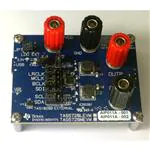
To help the user investigate and evaluate the TAS5270M performance and capabilities, a fully populated
evaluation board has been created. This board is shown in Figure 1-1. Connected to a PC, an external
power supply (4.5 V ≤ PVDD ≤ 26.4 V) and a signal source, the TAS5270M Evaluation Board easily
exercises the amplifier’s features.
Figure 1-1. TAS5720M Evaluation Board
2
Introduction
SLOU437 – December 2015
Submit Documentation Feedback
Copyright © 2015, Texas Instruments Incorporated
�Chapter 2
SLOU437 – December 2015
Quick Start Guide
1. Ensure all the jumpers are set correctly according to Table 2-1 and Figure 2-1.
2. Connect a speaker’s positive output terminal and negative output terminal respectively to OUTP (RED)
and OUTN (BLACK) on the EVM board. Be careful not to mix up OUTP and PVDD terminals, since the
colors are the same. The same applies to OUTN and GND terminals.
3. Connect a power supply (4.5 V-26.4 V) and ground reference respectively to PVDD (RED) and GND
(BLACK) on the EVM board.
4. Connect a micro USB cable to EVM and PC to generate 3.3 V supply.
5. Go to Control Panel, Sound and select USB-AudioEVM under the Playback tab. Click on Set
Default to make it the default playback device. Click on Properties and under the Advanced tab,
make sure that the Default Format is shown as 2 channel, 16 bit, 48000 Hz (DVD Quality) in Figure 22 below.
6. Power on the power supply after checking that all the connections are correctly.
7. Load a music file in the Windows Media Player. Play that audio file and listen to the output.
Table 2-1. TAS5720MEVM Default Jumper Settings
Jumper
Position
Comments
JP1
LEFT SIDE
Use LDO +3.3 V
JP2
IN
Enable Auto-Retry
SD
OUT
Keep device active
LRCLK
LEFT SIDE
Connect LRCLK to TAS5720M
MCLK
LEFT SIDE
Connect MCLK to TAS5720M
BCLK
LEFT SIDE
Connect BLK to TAS5720M
SDI
LEFT SIDE
Connect SDI to TAS5720M
SCL
LEFT SIDE
Connect SCL to TAS5720M
SDA
LEFT SIDE
Connect SDA to TAS5720M
SLOU437 – December 2015
Submit Documentation Feedback
Quick Start Guide
Copyright © 2015, Texas Instruments Incorporated
3
�www.ti.com
Figure 2-1. TAS5720MEVM Default Jumper Settings
4
Quick Start Guide
SLOU437 – December 2015
Submit Documentation Feedback
Copyright © 2015, Texas Instruments Incorporated
�www.ti.com
Figure 2-2. Default Format
SLOU437 – December 2015
Submit Documentation Feedback
Quick Start Guide
Copyright © 2015, Texas Instruments Incorporated
5
�Chapter 3
SLOU437 – December 2015
General Description
The TAS5720M device is a high-efficiency mono Class-D audio power amplifier optimized for high
transient power capability to use the dynamic power headroom of small loudspeakers. It is capable of
delivering more than 15-W continuously into a 4-Ω speaker. The device has two address pins, which allow
up to 8 I2C addressable devices to share a common TDM bus.
The TAS5720M device SAIF supports a variety of standard stereo serial audio formats including I2S, Left
Justified and Right Justified. It also supports a time division multiplexed (TDM) format that is capable of
transporting up to 8 channels of audio data on a single bus.
6
General Description
SLOU437 – December 2015
Submit Documentation Feedback
Copyright © 2015, Texas Instruments Incorporated
�Chapter 4
SLOU437 – December 2015
Operating Conditions
Table 4-1. Operating Conditions
PVDD and AVDD
4.5 V to 26.4 V
DVDD
3.0 V to 3.6 V
Minimum speaker load
3.2 Ω
I2C Clock Frequency
Up to 400 kHz
SLOU437 – December 2015
Submit Documentation Feedback
Operating Conditions
Copyright © 2015, Texas Instruments Incorporated
7
�Chapter 5
SLOU437 – December 2015
PCB Layout Guidelines
•
•
•
•
•
8
Pay special attention to the power stage power supply layout. Each H-bridge has two PVDD input pins
so that decoupling capacitors can be placed nearby. Use at least a 0.1-μF capacitor of X5R quality or
better for each set of inputs.
Keep the current circulating loops containing the supply decoupling capacitors, the H-bridges in the
device and the connections to the speakers as tight as possible to reduce emissions.
Use ground planes to provide the lowest impedance for power and signal current between the device
and the decoupling capacitors. The area directly under the device should be treated as a central
ground area for the device, and all device grounds must be connected directly to that area.
Use a via pattern to connect the area directly under the device to the ground planes in copper layers
below the surface. This connection helps to dissipate heat from the device.
Avoid interrupting the ground plane with circular traces around the device. Interruption disconnects the
copper and interrupt flow of heat and current. Radial copper traces are better to use if necessary.
PCB Layout Guidelines
SLOU437 – December 2015
Submit Documentation Feedback
Copyright © 2015, Texas Instruments Incorporated
�Chapter 6
SLOU437 – December 2015
Reference
This section includes the EVM schematic, board layout and BOM.
6.1
TAS5720MEVM Schematic
Figure 6-1 and Figure 6-2 illustrate the schematic for the TAS5720MEVM.
Figure 6-1. TAS5720MEVM Schematic (1 of 2)
SLOU437 – December 2015
Submit Documentation Feedback
Reference
Copyright © 2015, Texas Instruments Incorporated
9
�TAS5720MEVM PCB Layout
www.ti.com
Figure 6-2. TAS5720MEVM Schematic (2 of 2)
6.2
TAS5720MEVM PCB Layout
Figure 3 through Figure 12 illustrate the PCB layouts for this EVM.
Figure 3. Top Silkscreen
10
Reference
Figure 4. Top Solder Mask
SLOU437 – December 2015
Submit Documentation Feedback
Copyright © 2015, Texas Instruments Incorporated
�TAS5720MEVM PCB Layout
www.ti.com
Figure 5. Top Solder Paste
Figure 6. Top Layer
Figure 7. Layer 2
Figure 8. Layer 3
Figure 9. Bottom Layer
Figure 10. Bottom Silkscreen
SLOU437 – December 2015
Submit Documentation Feedback
Reference
Copyright © 2015, Texas Instruments Incorporated
11
�TAS5720MEVM Bill of Materials
www.ti.com
Figure 11. Bottom Solder Mask
6.3
Figure 12. Bottom Solder Paste
TAS5720MEVM Bill of Materials
Table 6-1. Bill of Materials
12
ITEM
MANU PART NUM
MANU
QTY
REF
DESIGNATORS
DESCRIPTION
1
TAS5720MRSM
TEXAS
INSTRUMENTS
1
U1
DIGITAL INPUT
MONO CLASS-D
AUDIO AMPLIFIER
QFN32-RSM ROHS
2
TAS1020BPFB
TEXAS
INSTRUMENTS
1
U2
USB STREAMING
CONTROLLER
TQFP48-PFB
ROHS
3
24LC256-I/MS
MICROCHIP
1
U3
SERIAL EEPROM
I2 C 256 K 400 kHz
MSOP8-MS ROHS
4
SN74LVC1G06DRL TEXAS
R
INSTRUMENTS
1
U4
LOW POWER
INVERTER OPEN
DRAIN OUTS
SOT553-DRL5
ROHS
5
SN74LVC1G125DR TEXAS
LR
INSTRUMENTS
1
U5
SINGLE BUS
BUFFER GATE
WITH 3-STATE
OUTPUT SOT553DRL5 ROHS
6
TPS3825-33DBVR
TEXAS
INSTRUMENTS
1
U6
PROCESSOR
SUPERVISORY
CIRCUITS 2.93 V
200 ms SOT23DBV5 ROHS
7
TPS7A4700RGWT
TEXAS
INSTRUMENTS
1
VR1
RF LDO VOLT
REG, 36 V,1 A,
4.17 uVRMS
QFN20-RGW
ROHS
8
MMBT2222A-7-F
DIODES INC.
1
Q1
TRANSISTOR NPN
GENERAL
PURPOSE 40 V 1 A
SOT23 DBV3
ROHS
Reference
SLOU437 – December 2015
Submit Documentation Feedback
Copyright © 2015, Texas Instruments Incorporated
�TAS5720MEVM Bill of Materials
www.ti.com
Table 6-1. Bill of Materials (continued)
9
625L3I006M00000
CTS FREQUENCY
CONTROLS
10
SMLP12BC7TT86
11
OSC1
OSCILLATOR SMT
6.0 MHz 3.3 V
OUT-ENABLE
ROHS
ROHM
1
SEMICONDUCTOR
USB-LOCK
LED BLUE
SMD0402 2.9 V 10
mA ROHS
LTST-C190EKT
LITE-ON INC.
1
FAULT
LED RED SMD0603
2.1 V 10 mA ROHS
12
LTST-C190GKT
LITE-ON INC.
1
3.3V
LED GREEN
SMD0603 2.1 V 10
mA ROHS
13
C1005X5R1A105K
TDK CORP
3
C1, C2, C3
CAP SMD0402
CERM 1.0 UFD 10
V 10% X5R ROHS
14
C1608X7R1H104K
TDK
2
C4, C9
CAP SMD0603
CERM 0.1 UFD 50
V 10% X7R ROHS
15
EEU-FC1J470
PANASONIC
2
C5, C10
CAP THRU ALUMELECT FC SERIES
47 ufd 63 V 20%
8x3.5x11.5 mm
ROHS
16
06033D224KAT2A
AVX
2
C6, C7
CAP SMD0603
CERM 0.22 UFD 25
V 10% X5R ROHS
17
GRM155R71C104K MURATA
A88J
10
C8, C13, C14, C15,
C16, C17, C18,
C19, C27, C30
CAP SMD0402
CERM 0.1 UFD 16
V X7R 10% ROHS
18
C2012X7R1H684M
125AB
2
C11, C12
CAP SMD0805
CERM 0.68 UFD 50
V 20% X7R ROHS
19
GMK316AB7106KL- TAIYO YUDEN
TR
1
C20
CAP SMD1206
CERM 10 UFD 35 V
10% X7R ROHS
20
JMK212BJ476MG-T TAIYO YUDEN
1
C21
CAP SMD0805
CERM 47 UFD 6.3
V 20% X5R ROHS
21
500R07N470JV4T
2
C22, C23
CAP SMD0402
CERM 47 pfd 50 V
5% COG ROHS
22
GMK107BJ105KA-T TAIYO YUDEN
1
C24
CAP SMD0603
CERM 1.0 UFD 35
V 10% X5R ROHS
23
CC0402JRNPO9BN YAGEO
101
1
C25
CAP SMD0402
CERM 100 pfd 50 V
5% NPO ROHS
24
GRM1555C1H102J
A01D
1
C26
CAP SMD0402
CERM 1000 pfd 5%
50 V COG ROHS
25
CGA2B2C0G1H100 DK CORP.
D050BD
1
C28
CAP SMD0402
CERM 10 pfd 50 V
+0.5 pfd COG
ROHS
26
GRM21BR70J106K
E76L
MURATA
1
C29
CAP SMD0805
CERM 10 UFD 6.3
V 10% X7R ROHS
27
MPZ1608S221A
TDK
2
FB1, FB2
FERRITE CHIP,
220 Ω 2 A 100 MHZ
SMD 0603 ROHS
TDK
JOHANSON
MURATA
1
SLOU437 – December 2015
Submit Documentation Feedback
Reference
Copyright © 2015, Texas Instruments Incorporated
13
�TAS5720MEVM Bill of Materials
www.ti.com
Table 6-1. Bill of Materials (continued)
14
28
ERJ-3GEY0R00V
PANASONIC
2
R3, R4
RESISTOR
SMD0603 0.0 Ω 5%
THICK FILM 1/10 W
ROHS
29
ERJ-2RKF4991X
PANASONIC
4
R5, R6, R17, R18
RESISTOR
SMD0402 4.99 K
1%,1/16 W ROHS
30
ERJ-3EKF1002V
PANASONIC
1
R7
RESISTOR
SMD0603 10.0 K
1% THICK FILM
1/10 W ROHS
31
CRCW0402360RFK VISHAY
ED
3
R8, R16, R23
RESISTOR
SMD0402 360 1/16
W 1% ROHS
32
CRCW040210K0FK VISHAY
ED
5
R9, R15, R24, R25,
R26
RESISTOR
SMD0402 10.0 K Ω
1% 1/16 W ROHS
33
RC0402FR-0715KL
YAGEO
1
R10
RESISTOR
SMD0402 THICK
FILM 15.0 K Ω 1%
1/16 W ROHS
34
RMCF0402FT1K50
STACKPOLE
ELECTRONICS
1
R11
RESISTOR
SMD0402 1.50K Ω
1% 1/16 W ROHS
35
ERJ-2RKF27R4X
PANASONIC
2
R12, R13
RESISTOR
SMD0402 THICK
FILM 27.4 Ω 1/10 W
1% ROHS
36
RC0402FR073K09L
YAGEO
1
R14
RESISTOR
SMD0402 THICK
FILM 3.09 K Ω 1%
1/16 W ROHS
37
RC0402FR-0747RL
YAGEO
4
R19, R20, R21, R22 RESISTOR
SMD0402 THICK
FILM 47.0 Ω 1%
1/16 W ROHS
38
1255AY-150M
TOKO JAPAN
2
Z1, Z2
INDUCTOR SMT 15
µH 3.3 A 63 mΩ
20% DG6045C
ROHS
39
PBC02SAAN
SULLINS
2
SD, JP2
HEADER THRU
MALE 2 PIN 100 LS
120 TAIL GOLD
ROHS
40
PBC03SAAN
SULLINS
8
J1, JP1, SCL, SDA,
SDI, BCLK, MCLK,
LRCLK
HEADER THRU
MALE 3 PIN 100 LS
120 TAIL GOLD
ROHS
41
ZX62WD1-B-5PC
HIROSE
1
USB
JACK USB
FEMALE TYPEB
MICRO SMT-RA
5PIN ROHS
42
7006
KEYSTONE
ELECTRONICS
2
OUTP, PVDD
BINDING POST,
RED, 15 A ECONO
ROHS
43
7007
KEYSTONE
ELECTRONICS
2
GND, OUTN
BINDING POST,
BLACK, 15 A
ECONO ROHS
44
969102-0000-DA
3M
11
J1, JP1, JP2, SCL,
SD, SDA, SDI,
BCLK, MCLK,
LRCLK
SHUNT BLACK AU
FLASH 0.100 LS
OPEN TOP ROHS
Reference
SLOU437 – December 2015
Submit Documentation Feedback
Copyright © 2015, Texas Instruments Incorporated
�TAS5720MEVM Bill of Materials
www.ti.com
Table 6-1. Bill of Materials (continued)
45
CRCW060322K1FK VISHAY
EA
0
R1, R2
RESISTOR
SMD0603 22.1 K Ω
1% 1/10 W ROHS
46
2027
KEYSTONE
ELECTRONICS
4
STANDOFFS
ROUND
STANDOFF 4-40
ALUM 1/2" ROHS
47
PMSSS 440 0025
PH
B&F FASTENER
4
STANDOFF
SCREWS
MACHINE SCREW
PAN PHILLIPS 4-40
ROHS
SLOU437 – December 2015
Submit Documentation Feedback
Reference
Copyright © 2015, Texas Instruments Incorporated
15
�IMPORTANT NOTICE
Texas Instruments Incorporated and its subsidiaries (TI) reserve the right to make corrections, enhancements, improvements and other
changes to its semiconductor products and services per JESD46, latest issue, and to discontinue any product or service per JESD48, latest
issue. Buyers should obtain the latest relevant information before placing orders and should verify that such information is current and
complete. All semiconductor products (also referred to herein as “components”) are sold subject to TI’s terms and conditions of sale
supplied at the time of order acknowledgment.
TI warrants performance of its components to the specifications applicable at the time of sale, in accordance with the warranty in TI’s terms
and conditions of sale of semiconductor products. Testing and other quality control techniques are used to the extent TI deems necessary
to support this warranty. Except where mandated by applicable law, testing of all parameters of each component is not necessarily
performed.
TI assumes no liability for applications assistance or the design of Buyers’ products. Buyers are responsible for their products and
applications using TI components. To minimize the risks associated with Buyers’ products and applications, Buyers should provide
adequate design and operating safeguards.
TI does not warrant or represent that any license, either express or implied, is granted under any patent right, copyright, mask work right, or
other intellectual property right relating to any combination, machine, or process in which TI components or services are used. Information
published by TI regarding third-party products or services does not constitute a license to use such products or services or a warranty or
endorsement thereof. Use of such information may require a license from a third party under the patents or other intellectual property of the
third party, or a license from TI under the patents or other intellectual property of TI.
Reproduction of significant portions of TI information in TI data books or data sheets is permissible only if reproduction is without alteration
and is accompanied by all associated warranties, conditions, limitations, and notices. TI is not responsible or liable for such altered
documentation. Information of third parties may be subject to additional restrictions.
Resale of TI components or services with statements different from or beyond the parameters stated by TI for that component or service
voids all express and any implied warranties for the associated TI component or service and is an unfair and deceptive business practice.
TI is not responsible or liable for any such statements.
Buyer acknowledges and agrees that it is solely responsible for compliance with all legal, regulatory and safety-related requirements
concerning its products, and any use of TI components in its applications, notwithstanding any applications-related information or support
that may be provided by TI. Buyer represents and agrees that it has all the necessary expertise to create and implement safeguards which
anticipate dangerous consequences of failures, monitor failures and their consequences, lessen the likelihood of failures that might cause
harm and take appropriate remedial actions. Buyer will fully indemnify TI and its representatives against any damages arising out of the use
of any TI components in safety-critical applications.
In some cases, TI components may be promoted specifically to facilitate safety-related applications. With such components, TI’s goal is to
help enable customers to design and create their own end-product solutions that meet applicable functional safety standards and
requirements. Nonetheless, such components are subject to these terms.
No TI components are authorized for use in FDA Class III (or similar life-critical medical equipment) unless authorized officers of the parties
have executed a special agreement specifically governing such use.
Only those TI components which TI has specifically designated as military grade or “enhanced plastic” are designed and intended for use in
military/aerospace applications or environments. Buyer acknowledges and agrees that any military or aerospace use of TI components
which have not been so designated is solely at the Buyer's risk, and that Buyer is solely responsible for compliance with all legal and
regulatory requirements in connection with such use.
TI has specifically designated certain components as meeting ISO/TS16949 requirements, mainly for automotive use. In any case of use of
non-designated products, TI will not be responsible for any failure to meet ISO/TS16949.
Products
Applications
Audio
www.ti.com/audio
Automotive and Transportation
www.ti.com/automotive
Amplifiers
amplifier.ti.com
Communications and Telecom
www.ti.com/communications
Data Converters
dataconverter.ti.com
Computers and Peripherals
www.ti.com/computers
DLP® Products
www.dlp.com
Consumer Electronics
www.ti.com/consumer-apps
DSP
dsp.ti.com
Energy and Lighting
www.ti.com/energy
Clocks and Timers
www.ti.com/clocks
Industrial
www.ti.com/industrial
Interface
interface.ti.com
Medical
www.ti.com/medical
Logic
logic.ti.com
Security
www.ti.com/security
Power Mgmt
power.ti.com
Space, Avionics and Defense
www.ti.com/space-avionics-defense
Microcontrollers
microcontroller.ti.com
Video and Imaging
www.ti.com/video
RFID
www.ti-rfid.com
OMAP Applications Processors
www.ti.com/omap
TI E2E Community
e2e.ti.com
Wireless Connectivity
www.ti.com/wirelessconnectivity
Mailing Address: Texas Instruments, Post Office Box 655303, Dallas, Texas 75265
Copyright © 2016, Texas Instruments Incorporated
�


 工商网监
湘ICP备2023018690号
工商网监
湘ICP备2023018690号
