TPIC84134-Q1
www.ti.com
SLDS176 – AUGUST 2010
LOW-FREQUENCY ANTENNA DRIVER
FOR PASSIVE START AND PASSIVE ENTRY
Check for Samples: TPIC84134-Q1
FEATURES
1
•
•
•
•
•
Output Stage Consists of Eight Programmable
Half-Bridge MOSFET Drivers (Configurable in
Half, Full, or Parallel Bridges) Which Deliver
Modulated Current to Each Coil
Linear Mode Output: Generates a Sine Wave
Voltage That is Controlled by the
Microcontroller
Output Stage is Overload Protected for Short
and Over Temperature
Driver Control and Diagnosis Blocks Drive the
Gates of the MOSFETS Via Data From the SPI
Antenna Diagnostics: Short to GND, Short to
VBAT, And Open Load Via Current
Measurement
•
•
•
•
Divider Block Generates an Internal Frequency
From the Input Clock (Main Controller); Used
for the Internal Logic
Sophisticated Failure Detection and Handling
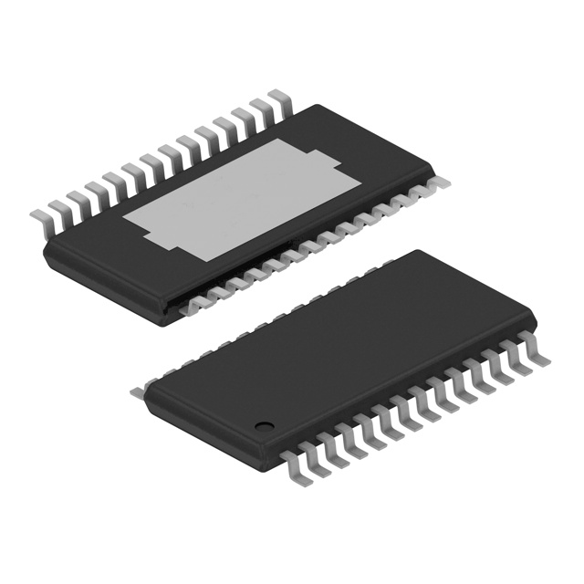
HTSSOP (PWP) 28-Pin Package
Operating Temperature Range:
-40°C to +105°C
APPLICATIONS
•
Automotive Passive Start and Passive Entry
Applications
DESCRIPTION
The low-frequency (LF) antenna driver is dedicated to automotive applications requiring passive entry or passive
start operational control. It allows for up to eight dedicated drivers, consisting of MOSFET transistors. The device
also incorporates sophisticated diagnosis, protection and monitoring features.
1
Please be aware that an important notice concerning availability, standard warranty, and use in critical applications of Texas
Instruments semiconductor products and disclaimers thereto appears at the end of this data sheet.
PRODUCTION DATA information is current as of publication date.
Products conform to specifications per the terms of the Texas
Instruments standard warranty. Production processing does not
necessarily include testing of all parameters.
Copyright © 2010, Texas Instruments Incorporated
�TPIC84134-Q1
SLDS176 – AUGUST 2010
www.ti.com
VS
VS/2
Sine Wave
Generation
Gains
Out 1
MUX
CLK_IN
VA
VD
Clock
Divider
Out 1
Power
Management
Current
Measurement
(ADC)
Out 2
Out 2
Out 3
Out 3
Out 4
Out 4
Out 5
Out 5
Out 6
Out 6
Out 7
Out 7
Out 8
Out 8
RBIAS
SDO
SDI
SPI
Control Logic
SCLK
NCS
GND
PGND
Figure 1. Block Diagram
ORDERING INFORMATION (1)
PACKAGE (2)
TA
–40°C to 105°C
(1)
(2)
2
HTSSOP – PWP
Reel of 2000
ORDERABLE PART NUMBER
TPIC84134TPWPRQ1
TOP-SIDE MARKING
TPIC84000TPWPRQ1
For the most current package and ordering information, see the Package Option Addendum at the end of this document, or see the TI
web site at www.ti.com.
Package drawings, thermal data, and symbolization are available at www.ti.com/packaging.
Submit Documentation Feedback
Copyright © 2010, Texas Instruments Incorporated
Product Folder Link(s): TPIC84134-Q1
�TPIC84134-Q1
www.ti.com
SLDS176 – AUGUST 2010
PWP PACKAGE
(TOP VIEW)
VS/2
1
28
VS
AT1
2
27
Out1
AT2
3
26
Out2
Test
4
25
PGND
VA
5
24
Out3
RBIAS
6
23
Out4
GND
7
22
VS
GND
8
21
VS
VD
9
20
Out5
CLK_IN
10
19
Out6
SDO
11
18
PGND
SDI
12
17
Out7
SCLK
13
16
Out8
NCS
14
15
VS
Exposed
Thermal
Pad
Submit Documentation Feedback
Copyright © 2010, Texas Instruments Incorporated
Product Folder Link(s): TPIC84134-Q1
3
�TPIC84134-Q1
SLDS176 – AUGUST 2010
www.ti.com
TERMINAL FUNCTIONS
4
NAME
NO.
I/O
DESCRIPTION
VS/2
1
O
VS/2 decoupling point. (Requires a 100nF, 10%, ESR < 50mΩ capacitor)
AT1
2
O
Internal use, connect to ground
AT2
3
O
Internal use, connect to ground
Test
4
I
Internal use, connect to ground
VA
5
I
Analog 5V supply
RBIAS
6
O
Current reference resistor (requires a 62kΩ, 1%, 50ppm resistor)
GND
7
-
Analog ground
GND
8
-
Digital ground
VD
9
I
Digital 5V supply
CLK_IN
10
I
Input clock signal
SDO
11
O
Serial data out for SPI
SDI
12
I
Serial data in for SPI
SCLK
13
I
Serial clock for SPI
NCS
14
I
Chip select for SPI (active low)
VS
15
I
Supply voltage
Out8
16
O
Output 8
Out7
17
O
Output 7
Pgnd
18
-
Power ground
Out6
19
O
Output 6
Out5
20
O
Output 5
VS
21
I
Supply voltage
VS
22
I
Supply voltage
Out4
23
O
Output 4
Out3
24
O
Output 3
Pgnd
25
-
Power ground
Out2
26
O
Output 2
Out1
27
O
Output 1
VS
28
I
Supply voltage
Thermal Pad
29
-
Must be connected to ground
Submit Documentation Feedback
Copyright © 2010, Texas Instruments Incorporated
Product Folder Link(s): TPIC84134-Q1
�TPIC84134-Q1
www.ti.com
SLDS176 – AUGUST 2010
DEVICE INFORMATION
The TPIC84134 is designed to control Passive Entry, Passive Start (PEPS) systems as a part of the central body
control module. Functionally, the TPIC84134 transmits a magnetic field signal via antenna coils located
throughout the vehicle. The data is transmitted using amplitude shift keying (ASK). Such a signal is received by
an external RFID card or key, which then activates the card or key to then process and send an authenticating
signal back to the vehicle, thus authenticating the driver. Once authenticated, the driver is able to open doors or
start the vehicle depending on the systems specific configuration. In general, the antenna load of the TPIC84134
is a coil, which generates a magnetic field which is high enough to transmit data to the ID card, and accurate
enough for location recognition outside of the vehicle.
Functional Description
Power Management
The TPIC84134 operates with three types of supply voltage: Digital 5V (VD), Analog 5V (VA ), and Power (VS).
While VD is used for the internal digital circuitry and VA voltage determines:
• The accuracy of the output voltage in data and destroy modes, because the sine wave signal is derived from
the VA voltage.
• The accuracy of the current measurements, because the Current Measurement (ADC) reference voltage is
derived from the VA voltage.
• The supply currents for the IC, as the bias current is derived from the VA voltage.
NOTE
VD and VA must be tied together to avoid latch up.
VS must be powered on all VS pins regardless of which outputs are used.
Biasing: Biasing of the circuit is done by an external resistor, RBIAS = 62kΩ, 1%, 50ppm. The value of the RBIAS
resistance determines:
• The accuracy of the current measurements, because the ADC reference voltage is proportional to the VA
voltage divided by the value of RBIAS.
• The supply currents for the IC, as the biasing current is proportional to the VA voltage divided by the value of
RBIAS.
Clock Divider
The Clock Divider generates a 2.1472 MHz internal clock signal from the external clock. The internal clock
frequency is used for:
• Clearing and latching the fault bits within Control and Status Register (CSR).
• For generating the frequency of the sine wave
The divider can be programmed to either: /1, /2, /4, /8, with the default being /8. Table 1 shows the possible
CLK_IN input frequencies to generate 134.2 kHz signal.
Table 1. Clock Divider
Divider
CLK_IN
/1
2.1472 MHz
/2
4.2944 MHz
/4
8.5888 MHz
/8 (default)
17.1776 MHz
Submit Documentation Feedback
Copyright © 2010, Texas Instruments Incorporated
Product Folder Link(s): TPIC84134-Q1
5
�TPIC84134-Q1
SLDS176 – AUGUST 2010
www.ti.com
To function properly the following conditions must be satisfied:
• The incoming clock (CLK_IN) has to be provided for at least 4 cycles of the internal clock after writing to
Configuration register via SPI
• In the case of a wake up command (i.e. sleep bit = 0 in the Config Reg), CLK_IN has to be provided during
124 additional cycles of the internal clock for fault blanking after writing the Config Register. During that time:
– Data1 buffer cannot be written to if sending mode bit in Config Reg is set to 1 (autosend mode).
– SPI command "Start Transmission" cannot be programmed
• In the case of CSR read and if a fault is cleared then, CLK_IN also has to be provided during a total of 128
clock cycles for the same reason of fault blanking.
CLK_IN electrical levels:
• When the CLK_IN is OFF, the electrical level should be high (typically 5V)
• The clock should be turned OFF after a low to high transition of CLK_IN
Sine Wave Generation
The sine wave generation block generates the 134.2 kHz sine wave from the internal clock. This sine wave is
used to generate the carrier frequency which is used for transmitting the signal as well as Destroy bits.
Note that the Destroy bits consist of bringing the selected channel to VS/2, transmitting a small number of bits
(1-4 programmable through SPI) at a reduced peak-to-peak voltage, then the channel is grounded again (HS off,
LS on). The purpose of the destroy bits is to actively stop any unwanted transmission signal that may be present
on the antenna due to coupling from the transmitting antenna.
For example, Figure 2 shows the first 6 Transmitted Bits (3 Manchester Bits) of a telegram together with three
destroy bits on the non-active outputs. The counter for start of destroy bits is set to 3, and it starts counting down
at the beginning of the transmission telegram denoted by "start" in the below diagram.
4.2 kBaud (Manchester encoded "100")
(V)
Data
0
1
0
1
0
1
VS
Out 1
VS/2
0
VS
Out 2
VS/2
0
Start
119
239
358
478
597
717
Time
(µs)
Figure 2. Transmitted Telegram Sample With Destroy Bits
6
Submit Documentation Feedback
Copyright © 2010, Texas Instruments Incorporated
Product Folder Link(s): TPIC84134-Q1
�TPIC84134-Q1
www.ti.com
SLDS176 – AUGUST 2010
Gains
Gain1 is a programmable gain for the output antenna working in normal mode to control the transmission power.
Gain2 allows the user to change the gain of the transmitted telegram for a programmable number of data bits
after which the telegram is continued in gain1. The time at which gain2 begins is programmable in the CSR;
alternatively, if the length of bits sent in gain2 is zero (0) the entire telegram is transmitted in gain1. Note, these
gains are not cascaded; it is either Gain1 or Gain2.
Gain for destroy bit transmission dictates the gain for the output channels set to "destroy bits". The gain for
destroy bits is a logarithmic scale and it is set to 500 mVpp by default.
Figure 3 shows an example in which Out1 is configured to transmit the telegram, using both Gain1 and Gain2.
The counter for start of transmission with Gain2 = 2 Bytes, and the counter for transmission in gain2 = 16 bits.
Note that the transmission resumes at Gain1 after the transmission at Gain2. The diagram also displays Out2
with destroy bits where counter for start of destroy bits = 8 bits, and Length of destroy = 4 bits.
Counter for start of
transmission with Gain 2:
( V )
2 Bytes
Counter for transmission
in Gain 2:
16 bits
G ain1
Out1
VS /2
G ain2
VS
0
Counter for start
:
of destroy bits
8 bits
VS
Out2
Gain
D estroy
VS /2
Length of
destroy bits :
4 bits
0
Start
8
16
32
56
Transmitted
Data (Bits)
Figure 3. Transmitted Telegram Sample Gain1 And Gain2
Multiplexer (Mux)
A multiplexer is used to pick between the various gains of the signal to each output, as well as selecting the
phase ( 0° or 180°) of the transmitting antennas.
A maximum of two outputs, or 2 half-bridges, can be activated at the same time in normal mode, where each is
designed to drive the required power into the antenna. Further, all other outputs can also be activated with
destroy bits at the same time(at a lower Vpp). As the bridges operate in a linear mode, the sine wave generation
at the bridge output is optimized to reduce EMI emissions and power dissipation.
Submit Documentation Feedback
Copyright © 2010, Texas Instruments Incorporated
Product Folder Link(s): TPIC84134-Q1
7
�TPIC84134-Q1
SLDS176 – AUGUST 2010
www.ti.com
Current Measurement
From a system's point of view, diagnostics of the antenna operation is done by measuring the load current
across the antenna and providing the measured value to the microcontroller via SPI. The microcontroller
retrieves the current value and evaluates if there is a failure or not. Within the TPIC84134 the current
measurement is done at each Low Side-transistor (LS), though the measurement of the various currents is done
sequentially (i.e. first LS1 measurement followed by the LS2 measurement, etc.). The actual measured analog
values are converted into five bit resolution digital values and are then stored in the control and status register.
As the load current can take between 2 to 10 wave-forms to reach its maximum value; current measurement can
depend on the actual application and the specific Q-factor of the antenna circuit. Therefore it is necessary to
program the exact time when the current measurement must be performed, and it is also necessary to measure
at the specific time within the wave to measure the maximum value.
A programmed parameter indicates which outputs are measured, where the low side of the programmed output
is measured sequentially. Here the edge (rising or falling) is also programmed, where during the odd (1st, 3rd,
5th, etc) rising or falling edge, the current on the low side of the first programmed output is measured; during the
even (2nd, 4th, 6th, etc) rising or falling edge, the current in the low side of the second programmed output is
measured. The measurement is performed continuously and the current value updated (over written) every time
within the Control and Status register.
Figure 4 shows an example of current measurement in a full-bridge configuration. In order to diagnose the
operation of the device in full-bridge, it is necessary to measure the current of LS1 and LS2. The two measured
values are stored in the Control and Status register.
Odd rising edge
Even rising edge
I_Antenna
I_LS2
LS2 measurement at second rising edge
(Timer2 programmed to 68: 31.902 µs)
I_LS1
LS1 measurement at first rising edge
(Timer1 programmed to 76: 35.627 µs)
0
7.5 14.9 22.4 29.8 37.3
0
7.5 14.9 22.4 29.8 37.3
Time
(µs)
Figure 4. Current Measurement Timing For Full Bridge Setup
Control Logic
The control logic block contains the SPI interface along with all the other circuitry necessary to convert the SPI
commands into the desired outputs.
8
Submit Documentation Feedback
Copyright © 2010, Texas Instruments Incorporated
Product Folder Link(s): TPIC84134-Q1
�TPIC84134-Q1
www.ti.com
SLDS176 – AUGUST 2010
Operation Modes
There are two operating modes: SLEEP mode and WAKE-UP mode.
In WAKE-UP mode, the device is either ready for the next transmission, or it is transmitting data. The wake-up
command and the output configuration command are separated to avoid noise on the VS/2 signal at wake up.
Note that the start command must happen at least 128 clock cycles after the wake-up command. The device
transitions from the WAKE-UP mode to the SLEEP mode when the following conditions occur:
• The Sleep bit in Configuration Register is set to 1 via SPI
or
• An over temperature fault condition is detected
or
• VS or VD under voltage is detected
In SLEEP mode, the sine wave generation block is off, the outputs are in tri-state, the SPI is functioning, but the
flags are not updated. The device goes from SLEEP mode to WAKE-UP mode when the following conditions
occur:
• The Sleep bit is set to 0 via the SPI
or
• The Sleep bit is set to 0 via the SPI and the CSR is read in case of an over temperature detection or VS
under voltage
NOTE
When operating in the tri-state mode, there is a pull down of typically 150 kΩ at the Outx
pins.
Diagnosis
As a function of protecting the TPIC84134 various diagnostic features such as over temperature warning, over
temperature pre-warning and energy limiting protection have been implemented. Flags within a register are used
to highlight a particular fault, or diagnosis, to the main controller, where each fault is essentially latched within the
register until it is read by SPI interface. After having been read by the SPI, the register is then cleared. This
protection scheme is implemented within the TPIC84134 itself, as follows:
Over Temperature
When over-temperature occurs while the device is operating in WAKE-UP mode; where upon over temperature
the device goes to SLEEP mode and the "over temperature" and "failure" flags are set to 1 in the CSR.
If the device is in SLEEP mode, it stays in this mode but no SPI flag is updated.
Temperature Pre-Warning
Temperature pre-warning has no impact on the operating mode of the device. If the device is in WAKE-UP
mode, the "temperature pre-warning" flag is set to 1 in the CSR; if the device is in SLEEP mode, no SPI flag is
updated.
Under Voltage
• VS under voltage: Occurs when VS goes below the VS under voltage threshold
– If the device is in WAKE-UP mode, it goes to SLEEP mode and the "under voltage at VS" and "failure"
flags are set to 1 in the CSR.
– If the device is in SLEEP mode, it stays in this mode but no SPI flag is updated.
• VD under voltage: Occurs when VD goes below the VD under voltage
– If the device is in WAKE-UP mode, it goes to SLEEP mode and the "under voltage at VD" and "failure"
flags are set to 1 in the CSR.
– If the device is in SLEEP mode, it stays in this mode but no SPI flag is updated.
Submit Documentation Feedback
Copyright © 2010, Texas Instruments Incorporated
Product Folder Link(s): TPIC84134-Q1
9
�TPIC84134-Q1
SLDS176 – AUGUST 2010
www.ti.com
IFAULT Flag: Energy Limiting Scheme
Two types of output device energy limiting schemes are used:
1. Detection of DC currents flowing in the output transistors
In normal operation, with an AC coupled load, continuous DC currents of greater than several mA will not
flow in the output transistors. If a current greater than 150mA (nominal) flows in either output transistor for a
duration greater than 4ms then the IFAULT condition will be activated and that channel will be placed in
tri-state. The exact time before the IFAULT is activated is a function of the voltage across the transistor
conducting >150mA load current. Larger voltages across this transistor will cause the deglitch time to be
shorter. With VS = 38V and with the output at VS/2 the minimum deglitch time is 4ms. The deglitch timer is
reset when the current level falls below 150mA.
2. Detection of excess bi-directional peak currents flowing in the output transistors
If a current greater than 0.9A flows in both output transistors when the sine wave signal is driven through the
output transistors, then the IFAULT condition will be activated and that channel will be placed in tri-state. The
IFAULT condition is activated when both high side and low side transistors have conducted >0.9A at any
time during the sine wave burst. The IFAULT signal will be activated immediately when the second output
transistor current exceeds 0.9A. The high side and low side detectors are reset during the transmission of a
"0" bit.
IFAULT has no impact on the operating mode.
• If the device is in WAKE-UP mode, the "IFAULT" and "failure" flags are set to 1 in the CSR and the channel
which has failed is put in tri-state.
• If the device is in SLEEP mode, no SPI flag is updated. However the data buffer will continue to be read out
until software stops the data buffer read by sending new Configuration data.
SPI Interface
A Serial Peripheral Interface (SPI) circuit is integrated into the device to set various internal registers and read
out current measurement and status information from the drivers. TPIC84134 operates in slave mode and the
microcontroller always acts as a master. The interface to the external micro-controller consists of 4 pins: NCS,
SCLK, SDO and SDI.
SPI Frame Structure
Each SPI communication frame for the TPIC84134 has a length of 64 bits, where it is forbidden to send more
than 64 bits. Each 64bit frame consists of 8 command-bits and 56-data-bits. The format of the 64 bits entering at
SDI and sent out at SDO is shown in Figure 5:
Figure 5. SPI Frame Structure
The MSB is the first "in" at the SDI and first "out" at the SDO, where the command sent out on SDO is the
command that was sent in the SDI's previous cycle
When NCS is high, any signals at the SCLK and SDI pins are ignored, and the SDO is forced into a high
impedance state.
During a High to Low transition on NCS, the SPI response word is loaded into a shift register, where the SCLK
pin must be low when NCS goes low.
At each rising edge of SCLK after NCS goes low, the response bit is serially shifted out on the SDO pin. Further,
the Control and Status register has to be cleared after readout at next NCS falling edge.
10
Submit Documentation Feedback
Copyright © 2010, Texas Instruments Incorporated
Product Folder Link(s): TPIC84134-Q1
�TPIC84134-Q1
www.ti.com
SLDS176 – AUGUST 2010
At each falling edge of SCLK (after NCS goes low), a new control bit is serially shifted in from the SDI pin. The
SPI command is decoded to determine the destination address for the associated data. After a complete frame is
received, during the next low to high transition on NCS, the SPI shift register data is transferred into the internal
memory at the last decoded address.
Bit 63
Bit 62
Bit 61
Bit 60
Bit 2
Bit 1
Bit 0
SDO
R63
R62
R61
R60
R2
R1
R0
SDI
D63
D62
D61
D60
D2
D1
D0
NCS
SCLK
Figure 6. SPI Protocol
Each SPI register in TPIC84134 has a length of 56 bits. The device has two registers for data transmission, one
configuration register and one control and status register (CSR).
Buffers for Data Transmission
The TPIC84134 has two buffers for data transmission with a size of 56 bits each, thus a maximum of 112bits can
be stored. After transmission begins, in order for the telegram to be endless, the buffers must be reloaded
continuously. The inactive buffer can be reloaded while the TPIC84134 is transmitting from the active buffer, and
the active buffer cannot be reloaded during transmission.
SPI Command Structure
The encoding of the specific SPI commands is based on, and specifically limited within the SPI shift register, to
64bits. Table 2 highlights the required basic commands to be sent via SPI. The encoding is optimized to reduce
the size of the digital part and to fulfill the application software preferences. One command and its associated
data are sent in the same frame. Any un-specified command or frame received by TPIC84134 will take the
device into an undefined state.
Submit Documentation Feedback
Copyright © 2010, Texas Instruments Incorporated
Product Folder Link(s): TPIC84134-Q1
11
�TPIC84134-Q1
SLDS176 – AUGUST 2010
www.ti.com
Basic Commands and Data Structure
Table 2. Commands
COMMAND
MSB....LSB
COMMAND DESCRIPTION
DATA SENT ON SDO AT NEXT FALLING EDGE OF NCS
0xxx xxxx
Read back the programmed register.
Programmed register
Programmed register will be loaded into SPI register at next
falling edge of NCS.
1xxx xxxx
Request control and status register.
The control and status register will be loaded into SPI
register at next falling edge of NCS.
1000 xxxx
x110 xxxx
x111 xxxx
No operation only feedback. Data bits are unused. The
Control and status register
control and status register will be loaded into SPI register at
next falling edge of NCS.
0000 xxxx
No operation only feedback.
All bits '0'
x001 xxxx
Program configuration register. Data bits contain data for
configuration register.
Programmed register or control and status register
depending on MSB
x010 xxxx
Program control and status register. Data bits contain data
for control and status register.
Control and status register whatever is the MSB
x011 xxxx
Program data buffer1. Data bits contain data for buffer1.
Programmed register or control and status register
depending to MSB
x100 xxxx
Program data buffer2. Data bits contain data for buffer2.
Programmed register or control and status register
depending to MSB
x101 xxxx
Start transmission. Data bits are unused. (When not in
automode)
Control and status register
Control and status register
The command that is sent out on SDO is the command that was sent on SDI at the previous cycle. The fifth MSB
bit is a failure bit which is set to '1' by the device when one of the following failures occurs: over temperature,
temperature pre-warning, under voltage at VS or VD, output over-current. Default is '0' for this bit then value is
latched until is read by SPI. This bit is the same as bit 18 in Control and Status register.
Figure 7. Format for 64 Bits Returned on SDO
12
Submit Documentation Feedback
Copyright © 2010, Texas Instruments Incorporated
Product Folder Link(s): TPIC84134-Q1
�TPIC84134-Q1
www.ti.com
SLDS176 – AUGUST 2010
Register Definitions
Table 3. Register Definitions
NAME
NO. OF
DESCRIPTION
BITS
DEFAULT VALUE
AT POR
MODE
R/W
SPI register
64
8 bit command 56 bit data
0........0
0...............0
R/W
Data buffer 1
56
56 bit data
0...............0
R/W
Data buffer 2
56
56 bit data
0...............0
R/W
clock division
2
00
01
10
11
= no division
= division by 2
= division by 4
= division by 8
Division by 8
R/W
baud rate
1
0 = 8.37 kHz Baud
1 = 16.75 kHz Baud
1
R/W
output 1
2
00
01
10
11
= LowSide "ON" – HighSide "OFF"
= transmit data with 180° phase
= transmit data with 0° phase
= transmit destroy bits
LowSide "ON"
HighSide "OFF"
R/W
output 2
2
00
01
10
11
= LowSide "ON" – HighSide "OFF"
= transmit data with 180° phase
= transmit data with 0° phase
= transmit destroy bits
LowSide "ON"
HighSide "OFF"
R/W
output 3
2
00
01
10
11
= LowSide "ON" – HighSide "OFF"
= transmit data with 180° phase
= transmit data with 0° phase
= transmit destroy bits
LowSide "ON"
HighSide "OFF"
R/W
2
00
01
10
11
= LowSide "ON" – HighSide "OFF"
= transmit data with 180° phase
= transmit data with 0° phase
= transmit destroy bits
LowSide "ON"
HighSide "OFF"
R/W
2
00
01
10
11
= LowSide "ON" – HighSide "OFF"
= transmit data with 180° phase
= transmit data with 0° phase
= transmit destroy bits
LowSide "ON"
HighSide "OFF"
R/W
2
00
01
10
11
= LowSide "ON" – HighSide "OFF"
= transmit data with 180° phase
= transmit data with 0° phase
= transmit destroy bits
LowSide "ON"
HighSide "OFF"
R/W
2
00
01
10
11
= LowSide "ON" – HighSide "OFF"
= transmit data with 180° phase
= transmit data with 0° phase
= transmit destroy bits
LowSide "ON"
HighSide "OFF"
R/W
2
00
01
10
11
= LowSide "ON" – HighSide "OFF"
= transmit data with 180° phase
= transmit data with 0° phase
= transmit destroy bits
LowSide "ON"
HighSide "OFF"
R/W
Gain1 for data transmission
5
00000 = 1Vpp
00001 = 2Vpp
…
11111 = 32Vpp
n = (n+1)Vpp
28Vpp (11011)
R/W
Gain2 for data transmission
5
00000 = 1Vpp
…
11111 = 32Vpp
n = (n+1)Vpp
14Vpp (01101)
R/W
gain for destroy-bit
transmission
4
0000 = 32/(2^15) Vpp
0001 = 32/(2^14) Vpp
…
1111 = 32 Vpp
32/(2^6) Vpp (1001)
R/W
Configuration register
output 4
output 5
output 6
output 7
output 8
Submit Documentation Feedback
Copyright © 2010, Texas Instruments Incorporated
Product Folder Link(s): TPIC84134-Q1
13
�TPIC84134-Q1
SLDS176 – AUGUST 2010
www.ti.com
Table 3. Register Definitions (continued)
NAME
NO. OF
DESCRIPTION
BITS
00 0000
…
11 1111 = after 63 data bytes
after x bytes the transmission will be sent with gain 2
DEFAULT VALUE
AT POR
MODE
R/W
00 0000
R/W
000 0000
R/W
000 010
R/W
1 bit
R/W
counter for start of
transmission with gain2
6
counter for bits transmitted
with gain2
7
counter for start of transmit
destroy bits
6
After x normal bits, destroy bits will be transmitted. Values
'000 000' and '000 001' are not allowed. If they are
programmed, this will give '000 010'.
length of destroy bit
2
00 = 1 bit
…
11 = 4 bit
selection of sending mode
1
0 = wait for trigger command via SPI
1 = start transmission as soon as buffer1 has received the
full 56 bits
1
R/W
Sleep bit
1
0 = wake-up mode
1= sleep mode (outputs are tri-state during this mode)
1
R/W
timer1 for current
measurement 1
9
time from 699ns to 237.75µs after selected edge (rising or
falling) 1st, 3rd ,5th ...
00...000: not used
00..001: 699 ns
00..010: 1164 ns
00..011: 1630 ns
…
11..101: 232.63 µs
11..110: 237.75 µs
11..111: not used
Timer (ns) = 232.86 ns + Bit data * 465.7228 ns (1) (2)
00..001
R/W
Must be set to "1" by micro
1
Bit must be set to "1" by the microcontroller to ensure
accurate current measurement
0
R/W
timer2 for current
measurement 2
9
time from 699ns to 237.75µs after selected edge (rising or
falling) 1st, 3rd ,5th ...
00...000: not used
00..001: 699 ns
00..010: 1164 ns
00..011: 1630 ns
…
11..101: 232.63 µs
11..110: 237.75 µs
11..111: not used
Timer (ns) = 232.86 ns + Bit data * 465.7228 ns (3) (4)
00..001
R/W
Must be set to "1" by micro
1
Bit must be set to "1" by microcontroller to ensure accurate
current measurement
0
R/W
trigger for measurement1
1
0 = measurement is done at 1st, 3rd ,5th ... rising edge of
Data_bit
1 = measurement is done at 1st , 3rd,5th... falling edge of
Data_bit
rising edge of Data_bit
R/W
trigger for measurement2
1
0 = measurement is done at 2nd , 4th,6th... rising edge of
Data_bit
1 = measurement is done at 2nd , 4th,6th... falling edge of
Data_bit
rising edge of Data_bit
R/W
3
000 = output 1
001 = output 2
010 = output 3
011 = output 4
…
0
R/W
000 0000 = 0 bit
…
1111111 = 127 bit
Control and Status Register
selected output for
measurement1
(1)
(2)
(3)
(4)
14
selected
selected
selected
selected
The programmed value must not exceed the duration of one bit at the chosen baud rate.
The programmed value can not be max value.
The programmed value must not exceed the duration of one bit at the chosen baud rate.
The programmed value can not be max value.
Submit Documentation Feedback
Copyright © 2010, Texas Instruments Incorporated
Product Folder Link(s): TPIC84134-Q1
�TPIC84134-Q1
www.ti.com
SLDS176 – AUGUST 2010
Table 3. Register Definitions (continued)
NAME
NO. OF
DESCRIPTION
BITS
selected output for
measurement2
3
000 = output 1
001 = output 2
010 = output 3
011 = output 4
…
selected
selected
selected
selected
unused
2
Bits unused
mode of device
2
0x = ready for next transmission
10 = busy – transmitting data 1
11 = busy – transmitting data 2
Sleep status
1
0 = wake-up mode
1= sleep mode (outputs are tri-state during this mode)
temperature pre-warning
1
over-temperature
DEFAULT VALUE
AT POR
MODE
R/W
1
R/W
additional there is the sleep
mode
R
1
R
0 = below pre-warning temperature
1 = above pre-warning temperature
Default is '0' then value is
latched until it is read by
SPI
R
1
0 = no over-temperature
1 = over-temperature
Default is '0' then value is
latched until it is read by
SPI
R
under voltage at VD
1
0 = normal supply voltage at VD
1 = under voltage at VD
Default is '0' then value is
latched until it is read by
SPI
R
under voltage at VS
1
0 = normal supply voltage at VS
1 = under voltage at VS
Default is '0' then value is
latched until it is read by
SPI
R
failure
1
0 = no failure
1 = one of the following failures: over-temperature, under
voltage at VS, or VD output over-current.
Default is '0' then value is
latched until it is read by
SPI
R
output over-current
8
0000 0001 = over-current
0000 0010 = over-current
0000 0011 = over-current
0000 0100 = over-current
…
Default is '0000 0000' then
value is latched until it is
read by SPI
R
current value 1
5
measured current at one active output
Default is '0 0000' then
value is latched until new
measurement is done
R
current value 2
5
measured current at other active output
Default is '0 0000' then
value is latched until new
measurement is done
R
on
on
on
on
output 1
output 2
outputs 1 and 2
output 3
Submit Documentation Feedback
Copyright © 2010, Texas Instruments Incorporated
Product Folder Link(s): TPIC84134-Q1
15
�TPIC84134-Q1
SLDS176 – AUGUST 2010
www.ti.com
Table 4. Typical Sequence of Commands
1.)
SPI Frame:
0001 xxxx
Program configuration register for wake up (outputs configured: High Side OFF – Low Side
ON)
SDO: Returns programmed register (config. Reg. in this case) Note 1.
2.)
SPI Frame:
0001 xxxx
3.)
SPI Frame:
0011 xxxx
4.)
SPI Frame:
0100 xxxx
Program configuration register for output configuration
SDO: Returns programmed register (config. Reg. in this case)
Program data1
SDO: Returns configuration data programmed in previous frame
Program data2
SDO: Returns data1 programmed in previous frame
5.)
SPI Frame:
*000 xxxx
6.)
SPI Frame:
1010 xxxx
No command
SDO: Returns data2 programmed in previous frame
Program triggers & timers for current measurement for diagnosis
SDO: Returns Config. Reg. or CSR (depending on MSB in last frame)
7.)
SPI Frame:
1101 xxxx
8.)
SPI Frame:
1010 xxxx
9.)
SPI Frame:
*000 xxx
Start transmission
SDO: Returns CSR (Control and Status register)
Re-program triggers & timers for new current measurement for diagnostics
SDO: Returns updated CSR (Control and Status register)
No command
SDO: Returns Config. Reg. or CSR (depending on MSB in last frame)
10.)
SPI Frame:
*001 xxx
Program config. Reg. for Sleep mode
SDO: Returns Config. Reg. or CSR (depending on MSB in last frame)
SPI Registers
Before being programmed, at POR, the TPIC84134 is in the default configuration. The default mode is sleep
mode and waiting for NCS. After POR, the SPI register (8bits command, 56bits data) is all "0". When it is in sleep
mode, the device will wake up when a "0" is programmed to "sleep bit" in configuration register. At wake up, the
registers remain with the same content as before standby. The wake-up command and the output configuration
command are separated to avoid noise on VS/2 signal at wake-up. The start command must happen at least 64
µs after the wake-up command. For transmission of LF on outputs, the MSB which is the first bit in the data
buffer is first out on LF driver.
16
Submit Documentation Feedback
Copyright © 2010, Texas Instruments Incorporated
Product Folder Link(s): TPIC84134-Q1
�TPIC84134-Q1
www.ti.com
SLDS176 – AUGUST 2010
APPLICATION OVERVIEW
Typical Application Circuit
U1
5V
62k, 0805, 1/10W, .5%, 25ppm
5V
GND
R1
VS
Out1
Out2
PGND
Out3
Out4
VS
VS
Out5
Out6
PGND
Out7
Out8
VS
28
27
26
25
24
23
22
21
20
19
18
17
16
15
R2
Out1
Out2
L_ant
R3
Out3
Out4
C_ant
Vs
R4
Out5
Out6
L_ant
Out7
Out8
Vs
C_ant
2
CLK_IN
SDO
SDI
SCLK
NCS
Vs
VS2_decoup
AT1
AT2
Test
VA
Rbias
AGND
DGND
VD
CLK_IN
SDO
SDI
SCLK
NCS
1
GND
1
2
3
4
5
6
7
8
9
10
11
12
13
14
2
1
1
C1
0.1uF, 0805, 100V, 10%, X7R, ESR


 工商网监
湘ICP备2023018690号
工商网监
湘ICP备2023018690号
