I2C Load Switch GUI and EVM Board
User's Guide
Literature Number: SLVU999C
October 2013 – Revised October 2014
�Contents
1
2
3
4
Description .......................................................................................................................... 4
1.1
Typical Applications ...................................................................................................... 4
1.2
Features ................................................................................................................... 4
Electrical Performance Specifications .................................................................................... 5
Setup – System Requirements - Windows 7 or XP ................................................................... 5
Device GUI SW .................................................................................................................... 7
4.1
High Level Functionality ................................................................................................. 8
4.2
Select U1 – U7
4.3
GPIO Mode or I2C Mode for Each Channel ......................................................................... 10
4.4
SwitchALL™ Functionality and Mode Registers .................................................................... 11
4.5
Scripting Functionality .................................................................................................. 13
...........................................................................................................
....................................................................................................
5.1
Schematics ..............................................................................................................
5.2
Layouts ...................................................................................................................
6
EVM Setup .........................................................................................................................
6.1
List of Test Points and Jumpers ......................................................................................
6.2
EVM USB Powered Mode .............................................................................................
6.3
EVM External Powered Mode .........................................................................................
7
Load Switch Performance ...................................................................................................
7.1
Switch Parallel Configuration Mode ..................................................................................
Revision History ..........................................................................................................................
5
2
Schematics and Layouts
Table of Contents
9
21
21
24
28
28
29
30
30
34
35
SLVU999C – October 2013 – Revised October 2014
Submit Documentation Feedback
Copyright © 2013–2014, Texas Instruments Incorporated
�www.ti.com
List of Figures
1
Select Run Administrator When Executing the Installer ................................................................ 5
2
I2C Load Switch Application Installer ...................................................................................... 5
3
Python Installer ............................................................................................................... 6
4
I2C Load Switch Board and USB2ANY Setup ............................................................................ 6
5
I2C Load Switch GUI Application Window ................................................................................ 7
6
Description of the Different Control in the GUI........................................................................... 8
7
Ways to Select Device Control ............................................................................................. 9
8
Set GPIO Mode or I2C Mode on Different Channels
9
Set U1 Mode1 Register to CH1 Enabled................................................................................ 11
10
Set U2 Mode1 Register to CH2 Enabled................................................................................ 12
11
Set SwitchALL™ Control to MODE1 to Send SwitchALL™ Command ............................................. 12
12
Launch Script Window ..................................................................................................... 14
13
Python Script Window Pops Up .......................................................................................... 14
14
Select Start Recording ..................................................................................................... 15
15
Python Script Window Begins Flashing Green ......................................................................... 15
16
GUI Screen after Clicking U2 CH1 Controls ............................................................................ 16
17
Python Script Window after Recording after Clicking U2 CH1 Controls ............................................ 16
18
Python Script Window Stop Recording .................................................................................. 17
19
Save Python Script Window .............................................................................................. 17
20
Must Enter the .py at the End of the File Name to Save the Python File Correctly ............................... 18
21
Select Exit on the Device GUI ............................................................................................ 18
22
Open Test_gui_script.py File
23
24
25
26
27
28
29
30
31
32
33
34
35
..................................................................
.............................................................................................
Run the Recorded Script ..................................................................................................
U2 Settings after Executing the Module and Running the Script ....................................................
I2C Load Switch EVM Board Schematic (1 of 3) .......................................................................
I2C Load Switch EVM Board Schematic (2 of 3) .......................................................................
I2C Load Switch EVM Board Schematic (3 of 3) .......................................................................
I2C Load Switch EVM Board Top Assembly ............................................................................
I2C Load Switch EVM Board Bottom Assembly ........................................................................
I2C Load Switch EVM Board Top Side (Minus GND Pour) ...........................................................
I2C Load Switch EVM Board Bottom Side (Minus GND Pour) .......................................................
Programmable Slew Rate Control .......................................................................................
Programmable Turn on Delay Time .....................................................................................
Programmable Output Discharge (Fall Time Control) .................................................................
TPS22993 All Four Switches Connected in Parallel Configuration .................................................
SLVU999C – October 2013 – Revised October 2014
Submit Documentation Feedback
Copyright © 2013–2014, Texas Instruments Incorporated
List of Figures
10
19
19
20
21
22
23
24
25
26
27
31
32
33
34
3
�User's Guide
SLVU999C – October 2013 – Revised October 2014
I2C Load GUI and EVM Board
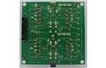
The I2C Load Switch EVM Board contains two quad channel load switch devices that are ultra-low
resistance (RON) with I2C programmable slew rate, delay time, and QOD channel. The I2C Load switch
EVM is available for both the TPS22993 and the TPS22994. Multiple I2C load switch EVM boards may be
connected together and controlled via a single I2C master.
1
Description
The I2C Load Switch is a multi-channel low RON load switch with user selectable controlled turn on. The
device contains four N-channel MOSFET devices that can operate over an input voltage range of 1.0 V to
3.6 V. The switch is controlled by I2C making it ideal for usage with processors that have limited GPIO
available. The rise time of the I2C Load Switch device is internally controlled in order to avoid inrush
current. The I2C Load Switch has five programmable slew rate options. The device also has adjustable
ON-delay as well as selectable quick output discharge (QOD) resistance.
The device can operate in either GPIO or I2C mode. The default mode of operation is GPIO control
through the ONx pins. The address pins can be tied high or low to assign seven unique addresses.
The I2C Load Switch is available in a space-saving WQFN package (0.4-mm pitch) and is characterized
for operation over the free-air temperature range of –40°C to 85°C.
1.1
Typical Applications
● Ultrabooks™
● Notebooks and Netbooks
● Tablet PC
1.2
● Consumer Electronics
● Smartphones
● Servers
Features
● EVM contains two I2C Load Switch devices, for a total of 8 independently controlled channels
— Additional I2C Load Switch EVMs can be daisy chained (up to 4 EVMs) to give a total of 28
channels that can be controlled independently via I2C
2
● I C control interface allows user to use any I2C capable microcontroller for evaluation of the EVM
— TI I2C capable microcontroller module (USB2ANY) included in EVM kit
— Daisy chained EVMs can only be controlled through I2C mode. USB2ANY can control only 2
devices through GPIO on the board it is directly connected to. The GPIO control for these 2
devices is accessed through the U1 and U2 tabs regardless of I2C address.
● Status LEDs for each channel output allows for quick debug of setup
● VIN input voltage range: 1V to 3.6V
● VBIAS voltage range: 4.5V to 17.2V
— Suitable for 2S/3S/4S Li-ion battery topologies
● TPS22993 is capable of up to 1.2 A continuous current per channel
● TPS22994 is capable of up to 1.0 A continuous current per channel
4
I2C Load GUI and EVM Board
SLVU999C – October 2013 – Revised October 2014
Submit Documentation Feedback
Copyright © 2013–2014, Texas Instruments Incorporated
�Electrical Performance Specifications
www.ti.com
2
Electrical Performance Specifications
For TPS22993 specifications refer to datasheet (SLVSCA3)
For TPS22994 specifications refer to datasheet (SLVSCL4)
3
Setup – System Requirements - Windows 7 or XP
(A) To install the software run the setup.application from the link below
(http://www.ti.com/tool/tps22993evm-033) by right clicking and saying “Run as Administrator, see
Figure 1.
Figure 1. Select Run Administrator When Executing the Installer
(B) You should see a pop up window asking you to install the software click “Yes” and then you should
see the window in Figure 2 pop up and click “Next” and agree to the terms and conditions in the
installer.
Figure 2. I2C Load Switch Application Installer
(C) You will see a Python installer begin, see Figure 3, let the installer complete and then click OK.
SLVU999C – October 2013 – Revised October 2014
Submit Documentation Feedback
Copyright © 2013–2014, Texas Instruments Incorporated
I2C Load GUI and EVM Board
5
�Setup – System Requirements - Windows 7 or XP
www.ti.com
Figure 3. Python Installer
(D) Connect the USB cable to the USB2ANY and then to the computer and connect the ribbon cable to
the EVM board. The setup should look like Figure 4 when you are done.
Figure 4. I2C Load Switch Board and USB2ANY Setup
6
I2C Load GUI and EVM Board
SLVU999C – October 2013 – Revised October 2014
Submit Documentation Feedback
Copyright © 2013–2014, Texas Instruments Incorporated
�Device GUI SW
www.ti.com
4
Device GUI SW
CAUTION
2
Do not launch the I C Load Switch GUI Application without having the
USBB2ANY plugged into the computer first.
(A) Go to All Programs >>> Texas Instrument >> I2C Load Switch GUI to launch the application.
(B) The I2C Load Switch GUI application window should pop on your screen, see Figure 5.
(C) You are ready to begin using the software and the demo board.
Figure 5. I2C Load Switch GUI Application Window
SLVU999C – October 2013 – Revised October 2014
Submit Documentation Feedback
Copyright © 2013–2014, Texas Instruments Incorporated
I2C Load GUI and EVM Board
7
�Device GUI SW
4.1
www.ti.com
High Level Functionality
(A) The HL U1 – U7 Tabs contain high level controls that set the device to specific register settings. Each
change in the control value results in a register write to the device.
(B) There are 6 different controls for each channel on the device
• CHx GPIO/I2C Mode
• CHx I2C Disable/Enable
• CHx GPIO Disable/Enable
• CHx QOD resistance
• CHx Turn On Slew Rate
• CHx Turn On Delay Time
(C) The GUI also provides Mode Register Controls for each device
(D) The SwitchALL™ control communicates with all devices simultaneously.
(E) See Figure 6 showing the different controls (SwitchALL™, Channel Controls, MODE Registers)
Figure 6. Description of the Different Control in the GUI
8
I2C Load GUI and EVM Board
SLVU999C – October 2013 – Revised October 2014
Submit Documentation Feedback
Copyright © 2013–2014, Texas Instruments Incorporated
�Device GUI SW
www.ti.com
4.2
Select U1 – U7
(A) You can navigate to the controls for U1 – U7 in two different ways.
(B) The first way is by clicking the device tab (U1, U2, U3, etc.).
(C) The second way is by clicking the high level functions on the left side of the screen, see Figure 7.
(D) Be sure that the I2C address is properly configured using jumper points JP7, JP9, JP11, JP20, JP22,
and JP23. The configured address should correspond to the address appearing on the specific device
tab.
Figure 7. Ways to Select Device Control
SLVU999C – October 2013 – Revised October 2014
Submit Documentation Feedback
Copyright © 2013–2014, Texas Instruments Incorporated
I2C Load GUI and EVM Board
9
�Device GUI SW
4.3
www.ti.com
2
GPIO Mode or I C Mode for Each Channel
(A) The CHx GPIO Mode/I2C Mode Control will set the channel on that specific device to respond to either
the GPIO Enable Pin or the I2C EN register bit. See Figure 8 showing CH1 and CH2 of U1 are set to
the 2 different modes.
(B) Also the disable/enable control for the alternate mode will become inactive to the user. In Figure 8, I2C
CH1 Disable is pink which indicates this does not have an effect on the output of CH1 and this is the
same for GPIO CH2 Disabled; the user will not be able to change the value on the high level page until
the channel mode selection has been changed. Figure 8 shows the controls that are active and deactivated for CH1 and CH2.
Figure 8. Set GPIO Mode or I2C Mode on Different Channels
10
I2C Load GUI and EVM Board
SLVU999C – October 2013 – Revised October 2014
Submit Documentation Feedback
Copyright © 2013–2014, Texas Instruments Incorporated
�Device GUI SW
www.ti.com
4.4
SwitchALL™ Functionality and Mode Registers
(A) To use the SwitchAll™ function, the GUI CONFIG controls for all channels must be set to the I2C
Mode, and the I2C communication must be enabled.
(B) You can use the SwitchALL™ functionality by configuring the Mode Register controls for each specific
mode register on the two devices.
(C) For example U1 MODE1 is configured to enable CH1 only and U2 MODE1 is configured to enable
CH2 only, you must set these first before sending the SwitchALL™ command, see Figure 9 and
Figure 10.
(D) Once you set the SwitchALL™ control to MODE1 then SwitchALL™ command will be sent to both
devices and each device will respond according to how you have configured the MODE1 register for
that device, see Figure 11.
Figure 9. Set U1 Mode1 Register to CH1 Enabled
SLVU999C – October 2013 – Revised October 2014
Submit Documentation Feedback
Copyright © 2013–2014, Texas Instruments Incorporated
I2C Load GUI and EVM Board
11
�Device GUI SW
www.ti.com
Figure 10. Set U2 Mode1 Register to CH2 Enabled
Figure 11. Set SwitchALL™ Control to MODE1 to Send SwitchALL™ Command
12
I2C Load GUI and EVM Board
SLVU999C – October 2013 – Revised October 2014
Submit Documentation Feedback
Copyright © 2013–2014, Texas Instruments Incorporated
�Device GUI SW
www.ti.com
4.5
Scripting Functionality
(A) Restart the Device GUI to insure the GUI starts with the known default values.
(B) Go to the drop down menu Script >> Launch window as shown in Figure 12.
(C) A Python scripting window should be launched named Untitled as shown in Figure 13.
(D) Go to the drop down menu Script >> Start Recording, see Figure 14
(E) The Python script should begin flashing green and additional text should show up in the window, see
Figure 15.
(F) You are now ready to record the actions in the I2C Load Switch GUI. Click on the U2 tab to select
device U2. Click on CH1 GPIO Mode it should transition to CH1 I2C MODE, Click on I2C CH1 Disable
and it should transition to I2C CH1 Enabled and turn Green, Click on U2 CH1 QOD and select 110 Ω,
Click on U2 CH1 Slew Rate and select 250 µs/V, and Click on U2 CH1 ON Delay and select 105 µs.
(G) Your GUI screen should look like Figure 16 after you have finished clicking the controls.
(H) These steps should have been recorded in the Python script GUI, see Figure 17.
(I) Go to the script drop down menu and select Stop Recording, see Figure 18. The Python window
should now have the GUI.__del__() command added to the last of the script and the Python window
should have stopped flashing green.
(J) Open the Python window and go to File >> Save As, see Figure 19
(K) Browse to the Desktop and put the file name as test_gui_script.py (to save the file, you must enter the
.py file extension at the end of the file name, for example, test.py) and save it to the desktop, see
Figure 20.
(L) Go to the I2C Load Switch GUI and Select File>> Exit, see Figure 21 to exit the application.
(M) Restart the application and go to Script >>> Launch Window.
(N) In the Python window go to File >> Open>> and Browse to the test_gui_script.py file on the desktop,
see Figure 22.
(O) In the Python window go to Run >> Run Module, see Figure 23. The Python script should run and
another python window should pop us saying Script Completed Successfully.
(P) The I2C Load Switch GUI setting for U2 CH2 should now be updated to the setting from the recording
after restarting the application and running the script, see Figure 24.
SLVU999C – October 2013 – Revised October 2014
Submit Documentation Feedback
Copyright © 2013–2014, Texas Instruments Incorporated
I2C Load GUI and EVM Board
13
�Device GUI SW
www.ti.com
Figure 12. Launch Script Window
Figure 13. Python Script Window Pops Up
14
I2C Load GUI and EVM Board
SLVU999C – October 2013 – Revised October 2014
Submit Documentation Feedback
Copyright © 2013–2014, Texas Instruments Incorporated
�Device GUI SW
www.ti.com
Figure 14. Select Start Recording
Figure 15. Python Script Window Begins Flashing Green
SLVU999C – October 2013 – Revised October 2014
Submit Documentation Feedback
Copyright © 2013–2014, Texas Instruments Incorporated
I2C Load GUI and EVM Board
15
�Device GUI SW
www.ti.com
Figure 16. GUI Screen after Clicking U2 CH1 Controls
Figure 17. Python Script Window after Recording after Clicking U2 CH1 Controls
16
I2C Load GUI and EVM Board
SLVU999C – October 2013 – Revised October 2014
Submit Documentation Feedback
Copyright © 2013–2014, Texas Instruments Incorporated
�Device GUI SW
www.ti.com
Figure 18. Python Script Window Stop Recording
Figure 19. Save Python Script Window
SLVU999C – October 2013 – Revised October 2014
Submit Documentation Feedback
Copyright © 2013–2014, Texas Instruments Incorporated
I2C Load GUI and EVM Board
17
�Device GUI SW
www.ti.com
Figure 20. Must Enter the .py at the End of the File Name to Save the Python File Correctly
Figure 21. Select Exit on the Device GUI
18
I2C Load GUI and EVM Board
SLVU999C – October 2013 – Revised October 2014
Submit Documentation Feedback
Copyright © 2013–2014, Texas Instruments Incorporated
�Device GUI SW
www.ti.com
Figure 22. Open Test_gui_script.py File
Figure 23. Run the Recorded Script
SLVU999C – October 2013 – Revised October 2014
Submit Documentation Feedback
Copyright © 2013–2014, Texas Instruments Incorporated
I2C Load GUI and EVM Board
19
�Device GUI SW
www.ti.com
Figure 24. U2 Settings after Executing the Module and Running the Script
20
I2C Load GUI and EVM Board
SLVU999C – October 2013 – Revised October 2014
Submit Documentation Feedback
Copyright © 2013–2014, Texas Instruments Incorporated
�Schematics and Layouts
www.ti.com
5
Schematics and Layouts
5.1
Schematics
Figure 25. I2C Load Switch EVM Board Schematic (1 of 3)
I2C Load GUI and EVM Board
SLVU999C – October 2013 – Revised October 2014
Submit Documentation Feedback
Copyright © 2013–2014, Texas Instruments Incorporated
21
�Schematics and Layouts
www.ti.com
Figure 26. I2C Load Switch EVM Board Schematic (2 of 3)
22
I2C Load GUI and EVM Board
SLVU999C – October 2013 – Revised October 2014
Submit Documentation Feedback
Copyright © 2013–2014, Texas Instruments Incorporated
�Schematics and Layouts
www.ti.com
Figure 27. I2C Load Switch EVM Board Schematic (3 of 3)
I2C Load GUI and EVM Board
SLVU999C – October 2013 – Revised October 2014
Submit Documentation Feedback
Copyright © 2013–2014, Texas Instruments Incorporated
23
�Schematics and Layouts
5.2
www.ti.com
Layouts
Figure 28. I2C Load Switch EVM Board Top Assembly
24
I2C Load GUI and EVM Board
SLVU999C – October 2013 – Revised October 2014
Submit Documentation Feedback
Copyright © 2013–2014, Texas Instruments Incorporated
�Schematics and Layouts
www.ti.com
Figure 29. I2C Load Switch EVM Board Bottom Assembly
SLVU999C – October 2013 – Revised October 2014
Submit Documentation Feedback
Copyright © 2013–2014, Texas Instruments Incorporated
I2C Load GUI and EVM Board
25
�Schematics and Layouts
www.ti.com
Figure 30. I2C Load Switch EVM Board Top Side (Minus GND Pour)
26
I2C Load GUI and EVM Board
SLVU999C – October 2013 – Revised October 2014
Submit Documentation Feedback
Copyright © 2013–2014, Texas Instruments Incorporated
�Schematics and Layouts
www.ti.com
Figure 31. I2C Load Switch EVM Board Bottom Side (Minus GND Pour)
SLVU999C – October 2013 – Revised October 2014
Submit Documentation Feedback
Copyright © 2013–2014, Texas Instruments Incorporated
I2C Load GUI and EVM Board
27
�EVM Setup
6
www.ti.com
EVM Setup
Use Table 1 to connect to the EVM. Two operating modes will be explained further in Section 6.2 and
Section 6.3. A valid voltage level for VIN, VDD, and VBIAS must be present for proper switch operation.
6.1
List of Test Points and Jumpers
Table 1. Functions of Test Points and Jumpers
Test
Points
Name
Description
Default Setting
J1
USB2ANY Cable
Connects the USB2ANY to the EVM
Connected
J2
AUX EVM Bottom
Allows for an additional EVM connected to the EVM in use
Not Connected
J3
AUX EVM Top
Allows for an additional EVM connected to the EVM in use
Not Connected
JP1
EXT VIN /USB
Connects 3p3V USB2ANY or EXTPOWER VIN to VIN1-8 Jumpers
Short to USB 3.3 V
JP2
VIN1
Connects voltage to VIN1
Short
JP3
VBIAS1 /USB
Connects 5V USB2ANY voltage to VBIAS1
Short
JP4
VDD1
Connects 3.3V USB2ANY voltage to VDD1
Short
JP5
VIN2
Connects voltage to VIN2
Short
JP6
VIN3
Connects voltage to VIN3
Short
JP7
ADD3
Connects SWITCH1 ADD3 to GND or VDD1 (thru 10K ohms)
Short JP7 to 0
JP8
VIN4
Connects voltage to VIN4
Short
JP9
ADD2
Connects SWITCH1 ADD2 to GND or VDD1 (thru 10K ohms)
Short JP9 to 0
JP10
ON1
Connects SWITCH1 ON1 to GND or GPIO2
Short JP10 pin2 to 3
JP11
ADD1
Connects SWITCH1 ADD1 to GND or VDD1 (thru 10K ohms)
Short JP11 to 0
JP12
ON2
Connects SWITCH1 ON2 to GND or GPIO3
Short JP12 pin2 to 3
JP13
ON3
Connects SWITCH1 ON3 to GND or GPIO4
Short JP13 pin2 to 3
JP14
ON4
Connects SWITCH1 ON4 to GND or GPIO5
Short JP14 pin2 to 3
JP15
VDD2
Connects 3.3V USB2ANY voltage to VDD2
Short
JP16
VBIAS2 /USB
Connects 5V USB2ANY voltage to VBIAS2
Short
JP17
VIN5
Connects voltage to VIN5
Short
JP18
VIN6
Connects voltage to VIN6
Short
JP19
VIN7
Connects voltage to VIN7
Short
JP20
ADD3
Connects SWITCH2 ADD3 to GND or VDD1 (thru 10K ohms)
Short JP20 to 0
JP21
VIN8
Connects voltage to VIN8
Short
JP22
ADD2
Connects SWITCH2 ADD2 to GND or VDD1 (thru 10K ohms)
Short JP22 to 0
JP23
ADD1
Connects SWITCH2 ADD1 to GND or VDD1 (thru 10K ohms)
Short JP23 to 1
JP24
ON5
Connects SWITCH2 ON1 to GND or GPIO6
Short JP24 pin2 to 3
JP25
ON6
Connects SWITCH2 ON2 to GND or GPIO7
Short JP25 pin2 to 3
JP26
ON7
Connects SWITCH2 ON3 to GND or GPIO8
Short JP26 pin2 to 3
JP36
EXT 5.0V
Connects voltage for LED from switch
Short to USB5V
TP1
EXT VIN
Connection point foe EXT VIN input
TP2
VDD1
Connection point to VDD1
TP3
VBIAS1
Connection point to VBIAS1
TP4
VIN1
Connection point to VIN1
TP5
VOUT1
Connection point to VOUT1
TP6
VOUT1 SENSE
Connection point to VOUT1 SENSE
TP7
VIN2 SENSE
Connection point to VIN2 SENSE
TP8
VIN2
Connection point to VIN2
TP9
VOUT2
Connection point to VOUT2
TP10
VOUT2 SENSE
Connection point to VOUT2 SENSE
TP11
VIN2 SENSE
Connection point to VIN2 SENSE
TP16
VIN3
Connection point to VIN3
TP12-15
GND
Connection point to AGND
TP17
VOUT3
Connection point to VOUT3
28
I2C Load GUI and EVM Board
SLVU999C – October 2013 – Revised October 2014
Submit Documentation Feedback
Copyright © 2013–2014, Texas Instruments Incorporated
�EVM Setup
www.ti.com
Table 1. Functions of Test Points and Jumpers (continued)
Test
Points
Name
Description
TP18
VIN3 SENSE
Connection point to VIN3 SENSE
TP19
VOUT3 SENSE
Connection point to VOUT3 SENSE
TP20
VIN4
Connection point to VIN4
TP21
VOUT4
Connection point to VOUT4
TP22
VOUT4 SENSE
Connection point to VOUT4 SENSE
TP23
ON1
Connection point to ON1
TP24
VIN4
Connection point to VIN4
TP25
ON2
Connection point to ON2
TP26
ON3
Connection point to ON3
TP27
ON4
Connection point to ON4
TP28
VDD2
Connection point to VDD2
TP29
VBIAS2
Connection point to VBIAS2
TP30
VIN5
Connection point to VIN5
TP31
VOUT5
Connection point to VOUT5
TP32
VIN2 SENSE
Connection point to VIN2 SENSE
TP33
VOUT5 SENSE
Connection point to VOUT5 SENSE
TP34
VIN6
Connection point to VIN6
TP35
VOUT6
Connection point to VOUT6
TP36
VIN6 SENSE
Connection point to VIN6 SENSE
TP37
VOUT6 SENSE
Connection point to VOUT5 SENSE
TP38
VIN7
Connection point to VIN7
TP39
VOUT7
Connection point to VOUT7
TP40
SDA
Connection point to SDA
TP41
SCL
Connection point to SCL
TP42
VIN7 SENSE
Connection point to VIN7 SENSE
TP43
VOUT7 SENSE
Connection point to VOUT7 SENSE
TP44
VIN8
Connection point to VIN8
TP45
VOUT8
Connection point to VOUT8
TP46
ON5
Connection point to ON5
TP47
VOUT8 SENSE
Connection point to VOUT8 SENSE
TP48
VIN8 SENSE
Connection point to VIN8 SENSE
TP49
ON6
Connection point to ON6
TP50
ON7
Connection point to ON7
TP55
ON8
Connection point to ON8
TP51-54
GND
Connection point to AGND
6.2
Default Setting
EVM USB Powered Mode
When the jumpers are placed in the default setting described in Table 1. The USB2ANY module will
supply all necessary power (VIN, VDD, VBIAS, and VLED) for both U1 and U2 load switches. The
functionality of the load switches Trise, Tfall, Ton, and QOD can be programmed using the GUI
commands and viewed by connecting a scope to the desired switch output. When powering the I2C Load
Switch in the USB powered mode the user may NOT place excessive loads on the switch outputs. The
USB2ANY power sources are limited to 500 mA.
SLVU999C – October 2013 – Revised October 2014
Submit Documentation Feedback
Copyright © 2013–2014, Texas Instruments Incorporated
I2C Load GUI and EVM Board
29
�EVM Setup
6.3
www.ti.com
EVM External Powered Mode
External Power Sources can be connected directly to VIN, VDD, VBIAS, and VLED. To connect externally
to VIN move JP1 shunt to pin1 to pin2 position, and connect power source to TP1. (VIN operating voltage
levels are from 1.0V to 3.6V). When connecting VDD1 externally, remove JP4 shunt and connect power
source to TP2, for VDD2 remove shunt from JP15 and connect voltage to TP28. (VDD operating range is
1.62 to 3.6 V). To connect directly to VBIAS1 remove JP3 shunt and connect power source to TP3. For
VBIAS2 remove shunt from JP16 and connect power source to TP29. (VBIAS operating voltage levels are
from 4.5 to 17.2 V). External voltage can be applied for the LED’s place JP36 shunt on pin1 to 2 and
connect voltage source to TP56. (VLED = 4 V – 5 V). By connecting an external power source to the VIN
inputs the 1.2 A VOUT max continuous current limit may be exercised.
7
Load Switch Performance
The I2C Load Switch enables the user to set different slew rate, delay the turn on time, and control the
output discharge (or) turn off rate as desired using simple I2C commands. Examples of this flexibility are
shown in the sections below. Each switch channel is configurable independent of the other switch
channels.
Each switch channel is configurable independent of the other switch channels. Examples of this flexibility
are shown in the following plots using these test conditions:
• VIN = 2.6 V
• VBIAS = 7.2 V
• CIN = 1 µF
• COUT = 0.1 µF
• Rload = 10 Ω
• Temp = Room (~25°C)
30
I2C Load GUI and EVM Board
SLVU999C – October 2013 – Revised October 2014
Submit Documentation Feedback
Copyright © 2013–2014, Texas Instruments Incorporated
�Load Switch Performance
www.ti.com
Figure 32. Programmable Slew Rate Control
SLVU999C – October 2013 – Revised October 2014
Submit Documentation Feedback
Copyright © 2013–2014, Texas Instruments Incorporated
I2C Load GUI and EVM Board
31
�Load Switch Performance
www.ti.com
Figure 33. Programmable Turn on Delay Time
32
I2C Load GUI and EVM Board
SLVU999C – October 2013 – Revised October 2014
Submit Documentation Feedback
Copyright © 2013–2014, Texas Instruments Incorporated
�Load Switch Performance
www.ti.com
Figure 34. Programmable Output Discharge (Fall Time Control)
SLVU999C – October 2013 – Revised October 2014
Submit Documentation Feedback
Copyright © 2013–2014, Texas Instruments Incorporated
I2C Load GUI and EVM Board
33
�Load Switch Performance
7.1
www.ti.com
Switch Parallel Configuration Mode
Shorting resistors may be placed on the switch outputs to connect them in a parallel configuration; these
resistors are not populated when shipped. Placing a 0 Ω 2512 1W size resistor across R21 pads connects
switch1 VOUT1 and VOUT2 in parallel, R22 connects VOUT1 and VOUT4 and R23 connects VOUT3 and
VOUT4. Switch2 connects in the same manner using R24, R25, and R26. When connecting switches in
parallel the continuous current drawn through the device may be increased, and the On resistance (Ron)
across the parallel switch configuration is decreased. Figure 30 shows switch performance examples of
the TPS22993 in parallel configuration.
Figure 35. TPS22993 All Four Switches Connected in Parallel Configuration
34
I2C Load GUI and EVM Board
SLVU999C – October 2013 – Revised October 2014
Submit Documentation Feedback
Copyright © 2013–2014, Texas Instruments Incorporated
�Revision History
www.ti.com
Revision History
Changes from B Revision (September 2014) to C Revision .......................................................................................... Page
•
•
Updated Functions of Test Points and Jumpers table. ............................................................................. 28
Updated Functions of Test Points and Jumpers table. ............................................................................. 29
NOTE: Page numbers for previous revisions may differ from page numbers in the current version.
SLVU999C – October 2013 – Revised October 2014
Submit Documentation Feedback
Copyright © 2013–2014, Texas Instruments Incorporated
Revision History
35
�IMPORTANT NOTICE
Texas Instruments Incorporated and its subsidiaries (TI) reserve the right to make corrections, enhancements, improvements and other
changes to its semiconductor products and services per JESD46, latest issue, and to discontinue any product or service per JESD48, latest
issue. Buyers should obtain the latest relevant information before placing orders and should verify that such information is current and
complete. All semiconductor products (also referred to herein as “components”) are sold subject to TI’s terms and conditions of sale
supplied at the time of order acknowledgment.
TI warrants performance of its components to the specifications applicable at the time of sale, in accordance with the warranty in TI’s terms
and conditions of sale of semiconductor products. Testing and other quality control techniques are used to the extent TI deems necessary
to support this warranty. Except where mandated by applicable law, testing of all parameters of each component is not necessarily
performed.
TI assumes no liability for applications assistance or the design of Buyers’ products. Buyers are responsible for their products and
applications using TI components. To minimize the risks associated with Buyers’ products and applications, Buyers should provide
adequate design and operating safeguards.
TI does not warrant or represent that any license, either express or implied, is granted under any patent right, copyright, mask work right, or
other intellectual property right relating to any combination, machine, or process in which TI components or services are used. Information
published by TI regarding third-party products or services does not constitute a license to use such products or services or a warranty or
endorsement thereof. Use of such information may require a license from a third party under the patents or other intellectual property of the
third party, or a license from TI under the patents or other intellectual property of TI.
Reproduction of significant portions of TI information in TI data books or data sheets is permissible only if reproduction is without alteration
and is accompanied by all associated warranties, conditions, limitations, and notices. TI is not responsible or liable for such altered
documentation. Information of third parties may be subject to additional restrictions.
Resale of TI components or services with statements different from or beyond the parameters stated by TI for that component or service
voids all express and any implied warranties for the associated TI component or service and is an unfair and deceptive business practice.
TI is not responsible or liable for any such statements.
Buyer acknowledges and agrees that it is solely responsible for compliance with all legal, regulatory and safety-related requirements
concerning its products, and any use of TI components in its applications, notwithstanding any applications-related information or support
that may be provided by TI. Buyer represents and agrees that it has all the necessary expertise to create and implement safeguards which
anticipate dangerous consequences of failures, monitor failures and their consequences, lessen the likelihood of failures that might cause
harm and take appropriate remedial actions. Buyer will fully indemnify TI and its representatives against any damages arising out of the use
of any TI components in safety-critical applications.
In some cases, TI components may be promoted specifically to facilitate safety-related applications. With such components, TI’s goal is to
help enable customers to design and create their own end-product solutions that meet applicable functional safety standards and
requirements. Nonetheless, such components are subject to these terms.
No TI components are authorized for use in FDA Class III (or similar life-critical medical equipment) unless authorized officers of the parties
have executed a special agreement specifically governing such use.
Only those TI components which TI has specifically designated as military grade or “enhanced plastic” are designed and intended for use in
military/aerospace applications or environments. Buyer acknowledges and agrees that any military or aerospace use of TI components
which have not been so designated is solely at the Buyer's risk, and that Buyer is solely responsible for compliance with all legal and
regulatory requirements in connection with such use.
TI has specifically designated certain components as meeting ISO/TS16949 requirements, mainly for automotive use. In any case of use of
non-designated products, TI will not be responsible for any failure to meet ISO/TS16949.
Products
Applications
Audio
www.ti.com/audio
Automotive and Transportation
www.ti.com/automotive
Amplifiers
amplifier.ti.com
Communications and Telecom
www.ti.com/communications
Data Converters
dataconverter.ti.com
Computers and Peripherals
www.ti.com/computers
DLP® Products
www.dlp.com
Consumer Electronics
www.ti.com/consumer-apps
DSP
dsp.ti.com
Energy and Lighting
www.ti.com/energy
Clocks and Timers
www.ti.com/clocks
Industrial
www.ti.com/industrial
Interface
interface.ti.com
Medical
www.ti.com/medical
Logic
logic.ti.com
Security
www.ti.com/security
Power Mgmt
power.ti.com
Space, Avionics and Defense
www.ti.com/space-avionics-defense
Microcontrollers
microcontroller.ti.com
Video and Imaging
www.ti.com/video
RFID
www.ti-rfid.com
OMAP Applications Processors
www.ti.com/omap
TI E2E Community
e2e.ti.com
Wireless Connectivity
www.ti.com/wirelessconnectivity
Mailing Address: Texas Instruments, Post Office Box 655303, Dallas, Texas 75265
Copyright © 2014, Texas Instruments Incorporated
�


 工商网监
湘ICP备2023018690号
工商网监
湘ICP备2023018690号
