Please note that Cypress is an Infineon Technologies Company.
The document following this cover page is marked as “Cypress” document as this is the
company that originally developed the product. Please note that Infineon will continue
to offer the product to new and existing customers as part of the Infineon product
portfolio.
Continuity of document content
The fact that Infineon offers the following product as part of the Infineon product
portfolio does not lead to any changes to this document. Future revisions will occur
when appropriate, and any changes will be set out on the document history page.
Continuity of ordering part numbers
Infineon continues to support existing part numbers. Please continue to use the
ordering part numbers listed in the datasheet for ordering.
www.infineon.com
�CY8CKIT-041-40XX
PSoC® 4 S-Series Pioneer Kit Guide
Doc. # 002-10238 Rev. *D
Cypress Semiconductor
198 Champion Court
San Jose, CA 95134-1709
www.cypress.com
�Copyrights
Copyrights
© Cypress Semiconductor Corporation, 2016–2019. This document is the property of Cypress Semiconductor Corporation
and its subsidiaries (“Cypress”). This document, including any software or firmware included or referenced in this document
(“Software”), is owned by Cypress under the intellectual property laws and treaties of the United States and other countries
worldwide. Cypress reserves all rights under such laws and treaties and does not, except as specifically stated in this paragraph, grant any license under its patents, copyrights, trademarks, or other intellectual property rights. If the Software is not
accompanied by a license agreement and you do not otherwise have a written agreement with Cypress governing the use of
the Software, then Cypress hereby grants you a personal, non-exclusive, nontransferable license (without the right to sublicense) (1) under its copyright rights in the Software (a) for Software provided in source code form, to modify and reproduce
the Software solely for use with Cypress hardware products, only internally within your organization, and (b) to distribute the
Software in binary code form externally to end users (either directly or indirectly through resellers and distributors), solely for
use on Cypress hardware product units, and (2) under those claims of Cypress’s patents that are infringed by the Software
(as provided by Cypress, unmodified) to make, use, distribute, and import the Software solely for use with Cypress hardware
products. Any other use, reproduction, modification, translation, or compilation of the Software is prohibited.
TO THE EXTENT PERMITTED BY APPLICABLE LAW, CYPRESS MAKES NO WARRANTY OF ANY KIND, EXPRESS OR
IMPLIED, WITH REGARD TO THIS DOCUMENT OR ANY SOFTWARE OR ACCOMPANYING HARDWARE, INCLUDING,
BUT NOT LIMITED TO, THE IMPLIED WARRANTIES OF MERCHANTABILITY AND FITNESS FOR A PARTICULAR PURPOSE. No computing device can be absolutely secure. Therefore, despite security measures implemented in Cypress hardware or software products, Cypress shall have no liability arising out of any security breach, such as unauthorized access to
or use of a Cypress product. CYPRESS DOES NOT REPRESENT, WARRANT, OR GUARANTEE THAT CYPRESS PRODUCTS, OR SYSTEMS CREATED USING CYPRESS PRODUCTS, WILL BE FREE FROM CORRUPTION, ATTACK,
VIRUSES, INTERFERENCE, HACKING, DATA LOSS OR THEFT, OR OTHER SECURITY INTRUSION (collectively, “Security Breach”). Cypress disclaims any liability relating to any Security Breach, and you shall and hereby do release Cypress
from any claim, damage, or other liability arising from any Security Breach. In addition, the products described in these materials may contain design defects or errors known as errata which may cause the product to deviate from published specifications. To the extent permitted by applicable law, Cypress reserves the right to make changes to this document without further
notice. Cypress does not assume any liability arising out of the application or use of any product or circuit described in this
document. Any information provided in this document, including any sample design information or programming code, is provided only for reference purposes. It is the responsibility of the user of this document to properly design, program, and test
the functionality and safety of any application made of this information and any resulting product. “High-Risk Device” means
any device or system whose failure could cause personal injury, death, or property damage. Examples of High-Risk Devices
are weapons, nuclear installations, surgical implants, and other medical devices. “Critical Component” means any component of a High-Risk Device whose failure to perform can be reasonably expected to cause, directly or indirectly, the failure of
the High-Risk Device, or to affect its safety or effectiveness. Cypress is not liable, in whole or in part, and you shall and
hereby do release Cypress from any claim, damage, or other liability arising from any use of a Cypress product as a Critical
Component in a High-Risk Device. You shall indemnify and hold Cypress, its directors, officers, employees, agents, affiliates,
distributors, and assigns harmless from and against all claims, costs, damages, and expenses, arising out of any claim,
including claims for product liability, personal injury or death, or property damage arising from any use of a Cypress product
as a Critical Component in a High-Risk Device. Cypress products are not intended or authorized for use as a Critical Component in any High-Risk Device except to the limited extent that (i) Cypress’s published data sheet for the product explicitly
states Cypress has qualified the product for use in a specific High-Risk Device, or (ii) Cypress has given you advance written
authorization to use the product as a Critical Component in the specific High-Risk Device and you have signed a separate
indemnification agreement.
Cypress, the Cypress logo, Spansion, the Spansion logo, and combinations thereof, WICED, PSoC, CapSense, EZ-USB, FRAM, and Traveo are trademarks or registered trademarks of Cypress in the United States and other countries. For a more
complete list of Cypress trademarks, visit cypress.com. Other names and brands may be claimed as property of their respective owners.
PSoC® 4 S-Series Pioneer Kit Guide, Doc. # 002-10238 Rev. *D
2
�Contents
Safety Information
1. Introduction
1.1
1.2
1.3
1.4
1.5
1.6
1.7
1.8
32
Using the Kit Code Examples ....................................................................................32
Code Examples .........................................................................................................34
A. Appendix
A.1
A.2
A.3
A.4
A.5
A.6
20
Theory of Operation...................................................................................................20
KitProg2 .....................................................................................................................29
4. Code Examples
4.1
4.2
17
Before You Begin.......................................................................................................17
Install Software ..........................................................................................................17
Uninstall Software......................................................................................................19
3. Kit Operation
3.1
3.2
5
Kit Contents .................................................................................................................5
Board Details ...............................................................................................................6
PSoC Creator ............................................................................................................11
Getting Started...........................................................................................................14
Additional Learning Resources..................................................................................14
Technical Support......................................................................................................15
Documentation Conventions......................................................................................15
Acronyms...................................................................................................................15
2. Software Installation
2.1
2.2
2.3
4
36
Schematics ................................................................................................................36
Hardware Functional Description...............................................................................36
Using the FM24V10 F-RAM.......................................................................................44
Using EZ-BLE PRoC Module.....................................................................................46
Migrating Projects Across Different Pioneer Series Kits ............................................48
Bill of Materials ..........................................................................................................52
Revision History
PSoC® 4 S-Series Pioneer Kit Guide, Doc. # 002-10238 Rev. *D
53
3
�Safety Information
Regulatory Compliance
The CY8CKIT-041-40XX PSoC® 4 S-Series Pioneer Kit is intended for use as a development
platform for hardware or software in a laboratory environment. The board is an open system design,
which does not include a shielded enclosure. This may cause interference to other electrical or
electronic devices in close proximity. In a domestic environment, this product may cause radio
interference. In such cases, you may be required to take adequate preventive measures. In addition,
this board should not be used near any medical equipment or RF devices.
Attaching additional wiring to this product or modifying the product operation from the factory default
may affect its performance and cause interference with other apparatus in the immediate vicinity. If
such interference is detected, suitable mitigating measures should be taken.
The PSoC 4 S-Series Pioneer Kit, as shipped from the factory, has been verified to meet with the
requirements of CE as a Class A product.
The PSoC 4 S-Series Pioneer Kit contains electrostatic discharge (ESD) sensitive
devices. Electrostatic charges readily accumulate on the human body and any
equipment, and can discharge without detection. Permanent damage may occur on
devices subjected to high-energy discharges. Proper ESD precautions are
recommended to avoid performance degradation or loss of functionality. Store unused
PSoC 4 S-Series Pioneer kit in the protective shipping package.
End-of-Life/Product Recycling
The end-of life for this kit is five years from the date of manufacture mentioned as bar
code on the back of the box. Contact your nearest recycler for discarding the kit.
General Safety Instructions
ESD Protection
ESD can damage boards and associated components. Cypress recommends that you perform
procedures only at an ESD workstation. If an ESD workstation is not available, use appropriate ESD
protection by wearing an antistatic wrist strap attached to a grounded metal object.
Handling Boards
PSoC 4 S-Series Pioneer Kit is sensitive to ESD. Hold the board only by its edges. After removing
the board from its box, place it on a grounded, static-free surface. Use a conductive foam pad if
available. Do not slide the board over any surface.
PSoC® 4 S-Series Pioneer Kit Guide, Doc. # 002-10238 Rev. *D
4
�1.
Introduction
Thank you for your interest in the CY8CKIT-041-40XX PSoC® 4 S-Series Pioneer Kit. This kit
enables you to evaluate and develop your application using the PSoC 4000S device family.
The PSoC 4000S device family is an expansion to the PSoC 4 device family. PSoC 4000S device is
a true programmable embedded system-on-chip, integrating custom analog and digital peripheral
functions, memory, and an ARM® Cortex®-M0+ microcontroller on a single chip. The programmable
analog and digital peripheral functions allow higher flexibility, in-field tuning of the design, and faster
time-to-market.
The PSoC 4 S-Series Pioneer Kit offers footprint-compatibility with Arduino™ shields. This kit
features a CapSense® trackpad, two CapSense buttons, a CapSense proximity sensor that lets you
evaluate Cypress’s fourth-generation CapSense technology, an RGB LED, two user-configurable
push-button switches, potentiometer, an onboard programmer/debugger with USB-UART/I2C bridge
functionality block (KitProg2), a Cypress F-RAM™, an EZ-BLE™ PRoC™ Module, and a
rechargeable battery. This kit supports operating voltages of 1.9 V, 3 V (battery), 3.3 V or 5 V.
You will use PSoC Creator™ to develop and debug your PSoC 4000S device projects. PSoC
Creator is Cypress’s standard integrated design environment (IDE). If you are new to PSoC Creator,
see the documentation on the PSoC Creator home page. You can also refer the application note
AN79953 – Getting Started with PSoC 4, which gives an introduction to the PSoC 4 device.
1.1
Kit Contents
The CY8CKIT-041-40XX PSoC 4 S-Series Pioneer Kit contains the following, as shown in
Figure 1-1.
■
PSoC 4 S-Series Pioneer Kit
■
USB Standard-A to Micro-B cable
■
Water dropper
■
Four press-fit connectors (one 8x2, one 10x1, two 8x1)
■
Four jumper wires
■
Quick Start Guide
PSoC® 4 S-Series Pioneer Kit Guide, Doc. # 002-10238 Rev. *D
5
�Introduction
Figure 1-1. Kit Contents
Inspect the contents of the kit; if you find any part missing, contact your nearest Cypress sales office
for help: www.cypress.com/support.
1.2
Board Details
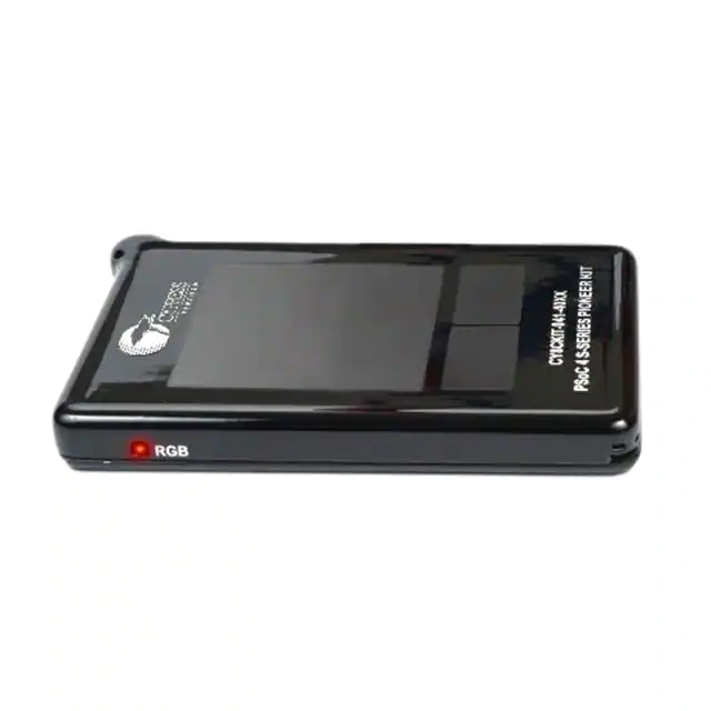
As shown in Figure 1-2, the PSoC 4 S-Series Pioneer Kit features a CapSense trackpad, two
CapSense buttons, and a proximity sensor loop (not visible on the case) that lets you evaluate
Cypress’s fourth-generation CapSense technology. The kit has two user buttons, an RGB LED and a
potentiometer that can be used in your applications. It also has a reset button and three status LEDs.
The kit can be powered from three power sources: USB connector, rechargeable battery or external
power supply. The kit can operate at 1.9 V, 3.3 V, and 5 V when powered from the USB connector or
external power supply and will operate at 3 V when powered from the battery. The USB connector is
also used for programming and debugging your application on PSoC 4000S.
PSoC® 4 S-Series Pioneer Kit Guide, Doc. # 002-10238 Rev. *D
6
�Introduction
Figure 1-2. PSoC 4 S-Series Pioneer Kit
PSoC® 4 S-Series Pioneer Kit Guide, Doc. # 002-10238 Rev. *D
7
�Introduction
Figure 1-3. PSoC 4 S-Series Pioneer Kit without Overlay
PSoC® 4 S-Series Pioneer Kit Guide, Doc. # 002-10238 Rev. *D
8
�Introduction
Figure 1-4. PSoC 4 S-Series Pioneer board (Top View)
PSoC® 4 S-Series Pioneer Kit Guide, Doc. # 002-10238 Rev. *D
9
�Introduction
Figure 1-5. PSoC 4 S-Series Pioneer board (Bottom View)
Figure 1-6. PSoC 4 S-Series Pioneer Board Pinout
PSoC® 4 S-Series Pioneer Kit Guide, Doc. # 002-10238 Rev. *D
10
�Introduction
Table 1-1. Jumpers/Switches Default Position
Jumper/Switch
Purpose
Default Position
SW4 (PWR SEL) VDD Source Selection
1.3
EXT (VREG/VBUS)
SW5
Programming Target Selection
PSoC 4000S
SW6
System Power (VDD) Selection
5V
SW7
Current Measurement Selection
Switches P1, P2, P3, and P4 – OFF;
Switch P5 – ON
PSoC Creator
PSoC Creator is a state-of-the-art, easy-to-use IDE. It introduces revolutionary hardware and software co-design, powered by a library of fully verified and characterized PSoC Components™, as
shown in Figure 1-7. With PSoC Creator, you can:
1. Drag and drop Components to build your hardware system design in the main design workspace
2. Co-design your application firmware with the PSoC hardware
3. Configure Components using configuration tools
4. Explore the library of 100+ Components
5. Access Component datasheets
Figure 1-7. PSoC Creator Features
PSoC Creator also enables you to tap into an entire tool ecosystem with integrated compiler chains
and production programmers for PSoC devices.
For more information, visit www.cypress.com/psoccreator.
PSoC® 4 S-Series Pioneer Kit Guide, Doc. # 002-10238 Rev. *D
11
�Introduction
1.3.1
PSoC Creator Code Examples
PSoC Creator includes a large number of code examples. These examples are accessible from the
PSoC Creator Start Page, as shown in Figure 1-8.
Code examples can speed up your design process by starting you off with a complete design. The
code examples also show how to use PSoC Creator Components for various applications. Code
examples and documentation are included, as shown in Figure 1-9.
In the Find Code Example dialog shown in Figure 1-9, you have several options:
■
Filter for examples based on device family or keyword.
■
Select from the list of examples offered based on the Filter Options.
■
View the project documentation for the selection (on the Documentation tab).
■
View the code for the selection on the Sample Code tab. You can also copy and paste code from
this window to your project, which can help speed up code development.
■
Create a new workspace for the code example or add to your existing workspace. This can speed
up your design process by starting you off with a complete, basic design. You can then adapt that
design to your application.
Figure 1-8. Code Examples in PSoC Creator
PSoC® 4 S-Series Pioneer Kit Guide, Doc. # 002-10238 Rev. *D
12
�Introduction
Figure 1-9. Code Example with Sample Code
1.3.2
Kit Code Examples
You can access the installed kit code examples from the PSoC Creator Start Page. To access these
examples, expand the Kits under the section Examples and Kits; then, expand the specific kit to see
the code examples. Refer to the Code Examples chapter on page 32 for a list of code examples that
you can use on this kit.
1.3.3
PSoC Creator Help
Launch PSoC Creator and navigate to the following items:
■
Quick Start Guide: Choose Help > Documentation > Quick Start Guide. This guide gives you
the basics for developing PSoC Creator projects.
■
Simple Component Code Examples: Choose File > Code Example. These examples demonstrate how to configure and use PSoC Creator Components. To access examples related to a
specific Component, right-click on the Component in the schematic or in the Component Catalog.
Select the Find Code Example option in the context menu that appears.
■
System Reference Guide: Choose Help > System Reference > System Reference Guide.
This guide lists and describes the system functions provided by PSoC Creator.
■
Component Datasheets: Right-click a Component and select Open Datasheet. Visit the
PSoC 4 Component Datasheets page for a list of all PSoC 4 Component datasheets.
■
Document Manager: PSoC Creator provides a document manager to help you easily find and
access the document resources. To open the document manager, choose the menu item Help >
Document Manager.
PSoC® 4 S-Series Pioneer Kit Guide, Doc. # 002-10238 Rev. *D
13
�Introduction
1.4
Getting Started
This guide will help you be acquainted with the PSoC 4 S-Series Pioneer Kit:
1.5
■
The Software Installation chapter on page 17 describes the installation of the kit software. This
includes the PSoC Creator IDE to develop and debug the applications, and PSoC Programmer to
program the .hex files on to the device.
■
The Kit Operation chapter on page 20 describes the major features of the PSoC 4 S-Series Pioneer Kit and functionalities such as programming, debugging, and the USB-UART and USB-I2C
bridges.
■
The Code Examples chapter on page 32 describes multiple PSoC 4000S code examples that will
help you understand how to create your own PSoC 4 projects.
■
The Appendix on page 36 provides the detailed hardware description, method to use the onboard
F-RAM, method to use the on board EZ-BLE PRoC Module, kit schematics, and the bill of materials (BOM).
Additional Learning Resources
Cypress provides a wealth of data at www.cypress.com to help you to select the right PSoC device
for your design, and to help you to quickly and effectively integrate the device into your design. For a
comprehensive list of resources, see KBA86521, How to Design with PSoC 3, PSoC 4, and
PSoC 5LP. The following is an abbreviated list for PSoC 4:
■
Overview: PSoC Portfolio and PSoC Roadmap.
■
Product Selectors: PSoC 4 Product Selector. In addition, PSoC Creator includes a device selection tool.
■
Datasheets: Describe and provide electrical specifications for the PSoC 4000, PSoC 4100,
PSoC 4200, PSoC 4100M, PSoC 4200M, PSoC 4200L, PSoC 4000S and PSoC 4100S device
families.
■
CapSense Design Guide: Learn how to design capacitive touch-sensing applications with the
PSoC 4 family of devices.
■
Application Notes and Code Examples: Cover a broad range of topics, from basic to advanced.
Many of the application notes include code examples. Visit the PSoC 3/4/5 Code Examples web
page for a list of all available PSoC Creator code examples. To access code examples from
within PSoC Creator – see PSoC Creator Code Examples on page 12.
■
Technical Reference Manuals (TRM): Provide detailed descriptions of the architecture and registers in each PSoC 4 device family.
■
Development Kits:
❐
CY8CKIT-041-40XX, CY8CKIT-041-41XX, CY8CKIT-046, CY8CKIT-044, CY8CKIT-042 and
CY8CKIT-040 are easy-to-use and inexpensive development platforms. These kits include
connectors for Arduino-compatible shields. Additionally, CY8CKIT-046, CY8CKIT-044, and
CY8CKIT-042 include connectors for Digilent Pmod Peripheral Modules.
❐
CY8CKIT-049, CY8CKIT-043 and CY8CKIT-145-40XX are very low-cost prototyping platform
for sampling PSoC 4 devices.
❐
CY8CKIT-001 is a common development platform for all PSoC family devices.
❐
MiniProg3 device provides an interface for flash programming and debug.
■
Knowledge Base Articles (KBA): Provide design and application tips from experts on using the
device.
■
Visit www.cypress.com/training for a set of tutorials, including PSoC Creator training. Each tutorial is a series of videos that provide practical examples on various topics starting with basic concepts and moving on to more advanced features.
PSoC® 4 S-Series Pioneer Kit Guide, Doc. # 002-10238 Rev. *D
14
�Introduction
1.6
Technical Support
For assistance, visit Cypress Support or contact customer support at +1(800) 541-4736 Ext. 2 (in the
USA) or +1 (408) 943-2600 Ext. 2 (International).
You can also use the following support resources if you need quick assistance:
1.7
■
Self-help (Technical Documents)
■
Local Sales Office Locations
Documentation Conventions
Table 1-2. Document Conventions for Guides
Convention
1.8
Usage
Courier New
Displays file locations, user entered text, and source code:
C:\...cd\icc\
Italics
Displays file names and reference documentation:
Read about the sourcefile.hex file in the PSoC Creator User Guide.
[Bracketed, Bold]
Displays keyboard commands in procedures:
[Enter] or [Ctrl] [C]
File > Open
Represents menu paths:
File > Open > New Project
Bold
Displays commands, menu paths, and icon names in procedures:
Click the File icon and then click Open.
Times New Roman
Displays an equation:
2+2=4
Text in gray boxes
Describes cautions or unique functionality of the product.
Acronyms
Table 1-3. Acronyms Used in this Document
Acronym
Definition
ADC
Analog-to-Digital Converter
BLE
Bluetooth Low Energy
BOM
Bill of Materials
CINT
Integration Capacitor
CMOD
Modulator Capacitor
CPU
Central Processing Unit
CSD
CapSense Sigma Delta
CTANK
Shield Tank Capacitor
DC
Direct Current
Del-Sig
Delta-Sigma
ESD
Electrostatic Discharge
F-RAM
Ferroelectric Random Access Memory
PSoC® 4 S-Series Pioneer Kit Guide, Doc. # 002-10238 Rev. *D
15
�Introduction
Table 1-3. Acronyms Used in this Document (continued)
Acronym
Definition
FPC
Flexible Printed Circuit
GPIO
General-Purpose Input/Output
HID
Human Interface Device
2
I C
Inter-Integrated Circuit
IC
Integrated Circuit
ICSP
In-Circuit Serial Programming
IDAC
Current Digital-to-Analog Converter
IDE
Integrated Development Environment
LED
Light-emitting Diode
PC
Personal Computer
PTC
Positive Temperature Coefficient
PRoC
Programmable Radio-on-Chip
PSoC
Programmable System-on-Chip
PWM
Pulse Width Modulation
RGB
Red Green Blue
SAR
Successive Approximation Register
SPI
Serial Peripheral Interface
SRAM
Serial Random Access Memory
SWD
Serial Wire Debug
UART
Universal Asynchronous Receiver Transmitter
USB
Universal Serial Bus
WCO
Watch Crystal Oscillator
PSoC® 4 S-Series Pioneer Kit Guide, Doc. # 002-10238 Rev. *D
16
�2.
Software Installation
This chapter describes the steps to install the software tools and packages on a PC for using the
PSoC 4 S-Series Pioneer Kit. This includes the IDE on which the projects will be built and used for
programming.
2.1
Before You Begin
To install Cypress software, you will require administrator privileges. However, they are not required
to run software that is already installed. Before you install the kit software, close any other Cypress
software that is currently running.
2.2
Install Software
Follow these steps to install the PSoC 4 S-Series Pioneer Kit software:
1. Download the CY8CKIT-041-40XX PSoC 4 S-Series Pioneer Kit software from
www.cypress.com/CY8CKIT-041. The kit software is available in three different formats for download.
a. CY8CKIT-041-40XX Kit Complete Setup: This installation package contains the files related
to the kit including PSoC Creator and PSoC Programmer. However, it does not include the
Windows Installer or Microsoft .NET framework packages. If these packages are not on your
computer, the installer directs you to download and install them from the Internet.
b. CY8CKIT-041-40XX Kit Only: This executable file installs only the kit contents, which include
kit code examples, hardware files, and user documents. This package can be used if all the
software prerequisites (listed in step 5) are installed on your PC.
c. CY8CKIT-041-40XX DVD ISO: This file is a complete package, stored in a DVD-ROM image
format, which you can use to create a DVD or extract using an ISO extraction program such
as WinZip® or WinRAR. The file can also be mounted like a virtual CD/DVD using virtual drive
programs such as Virtual CloneDrive and MagicISO. This file includes all the required software, utilities, drivers, hardware files, and user documents.
2. If you have downloaded the ISO file, mount it on a virtual drive. Extract the ISO contents if you do
not have a virtual drive to mount. Double-click cyautorun.exe in the root directory of the extracted
content or the mounted ISO if “Autorun from CD/DVD” is not enabled on the computer. The installation window will appear automatically.
Note: If you are using the “Kit Complete Setup” or “Kit Only” file, then go to step 4 for installation.
PSoC® 4 S-Series Pioneer Kit Guide, Doc. # 002-10238 Rev. *D
17
�Software Installation
3. Click Install CY8CKIT-041-40XX to start the PSoC 4 S-Series Pioneer Kit installation, as shown
in Figure 2-1.
Figure 2-1. Kit Installer Screen
4. Select the folder in which you want to install the PSoC 4 S-Series Pioneer Kit-related files.
Choose the directory and click Next.
5. When you click Next, the installer automatically installs the required software, if it is not present
on your computer. Following are the required software:
a. PSoC Creator 4.0 or later: This software is available for download separately at
www.cypress.com/psoccreator.
b. PSoC Programmer 3.25 or later: This is installed as part of PSoC Creator installation or is
available separately at www.cypress.com/programmer.
6. Choose the Typical, Custom, or Complete installation type (select Typical if you do not know
which one to select) in the Product Installation Overview window, as shown in Figure 2-2. Click
Next after you select the installation type.
PSoC® 4 S-Series Pioneer Kit Guide, Doc. # 002-10238 Rev. *D
18
�Software Installation
Figure 2-2. Product Installation Overview
7. Read the License agreement and select I accept the terms in the license agreement to continue with installation. Click Next.
8. When the installation begins, a list of packages appears on the installation page. A green check
mark appears next to each package after successful installation.
9. Enter your contact information or select the check box Continue Without Contact Information.
Click Finish to complete the CY8CKIT-041-40XX PSoC 4 S-Series Pioneer Kit software installation.
10.After the installation is complete, the kit contents are available at the following location:
\CY8CKIT-041-40XX PSoC 4 S-Series Pioneer Kit
Default location:
Windows 7 (64-bit): C:\Program Files (x86)\Cypress\CY8CKIT-041-40XX PSoC 4 SSeries Pioneer Kit
Windows 7 (32-bit): C:\Program Files\Cypress\CY8CKIT-041-40XX PSoC 4 S-Series
Pioneer Kit
Note: For Windows 7/8/8.1/10 users, the installed files and the folder are read only. To use the
installed code examples, follow the steps outlined in the Code Examples chapter on page 32. These
steps will create an editable copy of the example in a path that you choose so the original installed
example is not modified.
2.3
Uninstall Software
The software can be uninstalled using one of the following methods:
■
Go to Start > All Programs > Cypress > Cypress Update Manager and select the Uninstall
button that corresponds to the kit software.
■
Go to Start > Control Panel > Programs and Features for Windows 7 or Add/Remove Programs for Windows XP; choose the product and select the Uninstall/Change button.
PSoC® 4 S-Series Pioneer Kit Guide, Doc. # 002-10238 Rev. *D
19
�3.
Kit Operation
This chapter introduces you to the various features of the PSoC 4 S-Series Pioneer Kit, including the
theory of operation and the onboard programming and debugging functionality, KitProg2 USB-UART
and USB-I2C bridges.
3.1
Theory of Operation
The PSoC 4 S-Series Pioneer Kit is built around the PSoC 4000S device. Figure 3-1 shows the
block diagram of the PSoC 4000S device.
Figure 3-1. PSoC 4000S Block Diagram
PSoC® 4 One-Chip Solution
MCU Subsystem
Programmable Analog
Blocks
I/O Subsystem
GPIO x8
Smart
I/O
Flash
(16KB to 32KB)
SRAM
(2KB to 4KB)
CMP
x2
7-bit IDAC
x2
Single-Slope
ADC
CapSense
Programmable Digital
Blocks
WCO
TCPWM x5
Serial Wire Debug
SCB x2
Programmable Interconnect and Routing
48 MHz
Advanced High-Performance Bus (AHB)
Cortex®-M0+
GPIO x8
Smart
I/O
GPIOx8
GPIO x8
GPIO x4
PSoC® 4 S-Series Pioneer Kit Guide, Doc. # 002-10238 Rev. *D
20
�Kit Operation
Given below is a list of major features of PSoC 4000S device.
■
■
32-Bit MCU Subsystem
❐
48-MHz ARM® Cortex®-M0+ CPU
❐
Up to 32KB flash, 4KB SRAM
❐
Real-time clock capability with a WCO
Programmable Analog Blocks
❐
One 10-bit, 46.8-Ksps Single-Slope ADC
❐
Two low-power comparators (CMP)
❐
❐
■
■
One CapSense® block that supports low-power operation with self- and mutual-capacitance
sensing
Two 7-bit IDACs configurable as a single 8-bit IDAC
Programmable Digital Blocks
❐
Five 16-bit Timer, Counter, PWM (TCPWM) blocks
❐
Two serial communication blocks (SCBs) that are configurable as I2C, SPI or UART
Packages
❐
25-ball WLCSP, 24-pin QFN, 32-pin QFN, 48-pin TQFP
❐
Up to 36 GPIOs, including 16 Smart I/Os
Refer to the PSoC 4000S datasheet for details on device features.
Figure 3-2 shows the block diagram for the PSoC 4 S-Series Pioneer Kit.
Figure 3-2. Block Diagram of PSoC 4 S-Series Pioneer Kit
���
��+
�����
��� �
���
%�2�
��
����
�
(�� ��
�
�
���� ���
��6��
����)$�"
�
�
���
��
���
����
'�
�6�
�,����
�
���
��
��
�7*�(���
�
�
� ��
�
��+� �,"
(��������
�
�
�
� ��
�
��+� �,"
����
� �
��+
�������6�
���)
��������!
"��"##
$�%�!��
�>2'��
�����
������� ���
���+
��
��
� ����� ���,�
��"
���
��+
��)�
� ��
��$���+� �,"
�
�
���
��
���
�>2'��
�����
���
��������!
"��"##
$�%�!��
(�� ��
�)�
� ���
�('&��(*��#"
/�
�
�
�
����
�
���� �����
����
�%8�%��"
����
�
�
�
�
!�%�
�0-9:;


 工商网监
湘ICP备2023018690号
工商网监
湘ICP备2023018690号
