CY91460D Series
FR60 32-bit Microcontroller
CY91460D series is a line of general-purpose 32-bit RISC microcontrollers designed for embedded control applications which require
high-speed real-time processing, such as consumer devices and on-board vehicle systems. This series uses the FR60 CPU, which
is compatible with the FR family of CPUs.
This series contains the LIN-USART and CAN controllers.
Features
FR60 CPU Core
■
32-bit RISC, load/store architecture, five-stage pipeline
■
16-bit fixed-length instructions (basic instructions)
■
Instruction execution speed: 1 instruction per cycle
■
Instructions including memory-to-memory transfer, bit
manipulation, and barrel shift instructions: Instructions suitable
for embedded applications
■
Function entry/exit instructions and register data multi-load
store instructions : Instructions supporting C language
■
Register interlock function: Facilitating assembly-language
coding
■
Built-in multiplier with instruction-level support
❐ Signed 32-bit multiplication: 5 cycles
❐ Signed 16-bit multiplication: 3 cycles
■
Interrupts (save PC/PS) : 6 cycles (16 priority levels)
■
Harvard architecture enabling program access and data
access to be performed simultaneously
■
Instructions compatible with the FR family
■
Bit search module (for REALOS)
❐ Function to search from the MSB (most significant bit) for the
position of the first “0”, “1”, or changed bit in a word
■
LIN-USART (full duplex double buffer): 5 channels
❐ Clock synchronous/asynchronous selectable
❐ Sync-break detection
❐ Internal dedicated baud rate generator
■
■
CAN controller (C-CAN): 3 channels
❐ Maximum transfer speed: 1 Mbps
❐ 32 transmission/reception message buffers
■
Stepper motor controller : 6 channels
❐ 4 high current output to each channel
❐ 2 synchronized PWMs per channel (8/10-bit)
■
Sound generator : 1 channel
❐ Tone frequency : PWM frequency divide-by-two (reload value
1)
■
Alarm comparator : 1 channel
❐ Monitor external voltage
❐ Generate an interrupt in case of voltage lower/higher than
the defined thresholds (reference voltage)
■
16-bit PPG timer : 12 channels
■
16-bit PFM timer : 1 channel
■
16-bit reload timer: 8 channels
■
16-bit free-run timer: 8 channels (1 channel each for ICU and
OCU)
■
Input capture: 8 channels (operates in conjunction with the
free-run timer)
■
Output compare: 4 channels (operates in conjunction with the
free-run timer)
■
Up/Down counter: 3 channels (3*8-bit or 1*16-bit + 1*8-bit)
■
Watchdog timer
■
Real-time clock
■
Low-power consumption modes : Sleep/stop mode function
■
Supply Supervisor: Low voltage detection circuit for external
VDD5 and internal 1.8V core voltage
Internal Peripheral Resources
■
General-purpose ports : Maximum 170 ports
■
DMAC (DMA Controller)
❐ Maximum of 5 channels able to operate simultaneously.
(External to external : 1 channel)
❐ 3 transfer sources (external pin/internal peripheral/software)
❐ Activation source can be selected using software.
❐ Addressing mode specifies full 32-bit addresses
(increment/decrement/fixed)
❐ Transfer mode (demand transfer/burst transfer/step
transfer/block transfer)
❐ Fly-by transfer support (between external I/O and memory)
❐ Transfer data size selectable from 8/16/32-bit
❐ Multi-byte transfer enabled (by software)
❐ DMAC descriptor in I/O areas (200H to 240H, 1000H to
1024H)
■
■
A/D converter (successive approximation type)
❐ 10-bit resolution: 24 channels
❐ Conversion time: minimum 1 s
External interrupt inputs : 14 channels
❐ 8 channels shared with CAN RX or I2C pins
Cypress Semiconductor Corporation
Document Number: 002-04613 Rev. *B
•
I2C bus interface (supports 400 kbps): 3 channels
❐ Master/slave transmission and reception
❐ Arbitration function, clock synchronization function
198 Champion Court
•
San Jose, CA 95134-1709
•
408-943-2600
Revised November 17, 2017
�CY91460D Series
■
Clock supervisor
❐ Monitors the sub-clock (32 kHz) and the main clock
(4 MHz) , and switches to a recovery clock (CR oscillator,
etc.) when the oscillations stop.
■
Clock modulator
■
Clock monitor
■
Sub-clock calibration
❐ Corrects the real-time clock timer when operating with the 32
kHz or CR oscillator
■
Main oscillator stabilization timer
❐ Generates an interrupt in sub-clock mode after the
stabilization wait time has elapsed on the 23-bit stabilization
wait time counter
Document Number: 002-04613 Rev. *B
■
Sub-oscillator stabilization timer
❐ Generates an interrupt in main clock mode after the
stabilization wait time has elapsed on the 15-bit stabilization
wait time counter
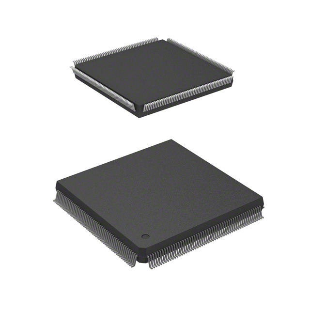
Package and Technology
■
Package : QFP-208
■
CMOS 0.18 m technology
■
Power supply range 3 V to 5 V (1.8 V internal logic provided by
a step-down voltage converter)
■
Operating temperature range: between
40°C and 105°C
Page 2 of 138
�CY91460D Series
Contents
Product Lineup ................................................................. 4
Pin Assignment ................................................................ 7
CY91F465DA, CY91F467Dx ....................................... 7
Pin Description ................................................................. 8
CY91F465DA, CY91F467Dx ....................................... 8
I/O Circuit Types ............................................................. 16
Handling Devices ............................................................ 22
Preventing Latch-up .................................................. 22
Handling of unused input pins ................................... 22
Power supply pins ..................................................... 22
Crystal oscillator circuit .............................................. 22
Notes on using external clock ................................... 22
Mode pins (MD_x) ..................................................... 23
Notes on operating in PLL clock mode ...................... 23
Pull-up control ........................................................... 23
Notes on PS register ................................................. 23
Notes on Debugger ........................................................ 24
Execution of the RETI Command .............................. 24
Break function ........................................................... 24
Operand break .......................................................... 24
Block Diagram ................................................................ 25
CY91F465DA, CY91F467Dx ..................................... 25
CPU and Control Unit ..................................................... 26
Features .................................................................... 26
Internal architecture ................................................... 26
Programming model .................................................. 27
Registers ................................................................... 28
Embedded Program/data Memory (Flash) ................... 31
Flash features ............................................................ 31
Document Number: 002-04613 Rev. *B
Operation modes ....................................................... 31
Flash access in CPU mode ....................................... 32
Parallel Flash programming mode ............................ 36
Poweron Sequence in parallel programming mode .. 38
Flash Security ............................................................ 38
Memory Space ................................................................ 41
Memory Maps .................................................................. 42
CY91F465DA, CY91F467Dx ..................................... 42
I/O Map ............................................................................. 43
CY91F465DA, CY91F467Dx ..................................... 43
Flash memory and external bus area ........................ 69
Interrupt Vector Table .................................................... 71
Recommended Settings ................................................. 76
PLL and Clockgear settings ...................................... 76
Clock Modulator settings ........................................... 77
Electrical Characteristics ............................................... 83
Absolute maximum ratings ........................................ 83
Recommended operating conditions ......................... 86
DC characteristics ..................................................... 87
A/D converter characteristics .................................... 91
Alarm comparator characteristics .............................. 95
FLASH memory program/erase characteristics ........ 96
AC characteristics ..................................................... 97
Ordering Information ................................................... 132
Package Dimension ...................................................... 133
Revision History ........................................................... 134
Document History ......................................................... 136
Page 3 of 138
�CY91460D Series
1. Product Lineup
CY91V460A
CY91F465DA
CY91F467DA
CY91F467DB
Max. core frequency (CLKB)
80MHz
100MHz
96MHz
Max. resource frequency (CLKP)
40MHz
50MHz
48MHz
Max. external bus freq. (CLKT)
40MHz
50MHz
48MHz
Max. CAN frequency
(CLKCAN)
20MHz
50MHz
48MHz
-
-
-
0.35μm
0.18μm
0.18μm
Watchdog timer
yes
yes
yes
Watchdog timer
(RC osc. based)
yes (disengageable)
yes
yes
Bit Search
yes
yes
yes
Reset input (INITX)
yes
yes
yes
Hardware Standby input (HSTX)
yes
no
no
Clock Modulator
yes
yes
yes
Clock Monitor
yes
yes
yes
Low Power Mode
yes
yes
yes
DMA
5 ch
5 ch
5 ch
Feature
Max. FlexRay frequency (SCLK)
Technology
MAC (uDSP)
no
MMU/MPU
MPU (16 ch)
no
1)
MPU (8 ch)
no
1)
MPU (8 ch) 1)
Emulation SRAM 32bit read
data
544 KByte
1088 KByte
Satellite Flash memory
-
no
no
Flash Protection
-
yes
yes
D-RAM
64 KByte
32 KByte
32 KByte
ID-RAM
64 KByte
16 KByte
32 KByte
Flash-Cache
(Instruction cache)
16 KByte
8 KByte
8 KByte
4 KByte fixed
4 KByte
4 KByte
RTC
1 ch
1 ch
1 ch
Free Running Timer
8 ch
8 ch
8 ch
ICU
8 ch
8 ch
8 ch
OCU
8 ch
4 ch
4 ch
Reload Timer
8 ch
8 ch
8 ch
Flash memory
Boot-ROM / BI-ROM
Document Number: 002-04613 Rev. *B
Page 4 of 138
�CY91460D Series
CY91V460A
CY91F465DA
CY91F467DA
CY91F467DB
PPG 16-bit
16 ch
12 ch
12 ch
PFM 16-bit
1 ch
1 ch
1 ch
Sound Generator
1 ch
1 ch
1 ch
4 ch (8-bit) / 2 ch (16-bit)
3 ch (8-bit) / 1 ch (16-bit)
3 ch (8-bit) / 1 ch (16-bit)
6 ch (128msg)
3 ch (32msg)
3 ch (32msg)
4 ch + 4 ch FIFO + 8 ch
1 ch + 4 ch FIFO
1 ch + 4 ch FIFO
4 ch
3 ch
3 ch
yes (32bit addr, 32bit data)
yes (26bit addr, 32bit data)
yes (26bit addr, 32bit data)
External Interrupts
16 ch
14 ch
14 ch
NMI Interrupts
1 ch
-
-
SMC
6 ch
6 ch
6 ch
LCD controller (40x4)
1 ch
-
-
ADC (10 bit)
32 ch
24 ch
24 ch
Alarm Comparator
2 ch
1 ch
1 ch
Supply Supervisor
(low voltage detection)
yes
yes
yes
Clock Supervisor
yes
yes
yes
Main clock oscillator
4MHz
4MHz
4MHz
Sub clock oscillator
32kHz
32kHz
32kHz
RC Oscillator
100kHz
100kHz / 2MHz
100kHz / 2MHz
PLL
x 20
x 25
x 24
DSU4
yes
-
-
EDSU
yes (32 BP) *1
yes (16 BP) *1
yes (16 BP) *1
3V / 5V
3V / 5V
3V / 5V
Regulator
yes
yes
yes
Power Consumption
n.a.
2
• if tSCYCI = (2*k 1)*tCLKP, then m = k 1, where k is an integer > 1
Notes :
• The above values are AC characteristics for CLK synchronous mode.
• tCLKP is the cycle time of the peripheral clock.
Document Number: 002-04613 Rev. *B
Page 99 of 138
�CY91460D Series
Internal Clock Mode (Master Mode)
tSCYCI
SCKn
for ESCR:SCES = 0
VOH
VOL
VOL
VOH
SCKn
for ESCR:SCES = 1
VOH
VOL
tSLOVI
tOVSHI
VOH
VOL
SOTn
tIVSHI
tSHIXI
VOH
VOL
SINn
VOH
VOL
External Clock Mode (Slave Mode)
tSLSHE
SCKn
for ESCR:SCES = 0
VOH
SCKn
for ESCR:SCES = 1
VOL
tSHSLE
VOH
VOL
VOL
VOH
VOH
VOL
VOH
VOL
tRE
tFE
tSLOVE
SOTn
VOH
VOL
tIVSHE
SINn
Document Number: 002-04613 Rev. *B
VOH
VOL
tSHIXE
VOH
VOL
Page 100 of 138
�CY91460D Series
15.7.4 I2C AC Timings at VDD5 = 3.0 to 5.5 V
• Conditions during AC measurements
All AC tests were measured under the following conditions:
- IOdrive = 3 mA
- VDD5 = 3.0 V to 5.5 V, Iload = 3 mA (VDD = 4.5 V to 5.5 V for CY91F467Dx)
- VSS5 = 0 V
- Ta = 40°C to 105°C
- Cl = 50 pF
- VOL = 0.3 × VDD5
- VOH = 0.7 × VDD5
- EPILR = 0, PILR = 0 (CMOS Hysteresis 0.3 × VDD5/0.7 × VDD5)
Fast Mode:
(VDD5 = 3.5 V to 5.5 V, VSS5 = AVSS5 = 0 V, TA = 40°C to 105°C)
Parameter
Symbol
Pin Name
fSCL
Value
Unit
Remark
Min
Max
SCLn
0
400
kHz
tHD;STA
SCLn, SDAn
0.6
—
μs
LOW period of the SCL clock
tLOW
SCLn
1.3
—
μs
HIGH period of the SCL clock
tHIGH
SCLn
0.6
—
μs
Setup time for a repeated START
condition
tSU;STA
SCLn, SDAn
0.6
—
μs
Data hold time for I2C-bus devices
tHD;DAT
SCLn, SDAn
0
0.9
μs
Data setup time
tSU;DAT
SCLn SDAn
100
—
ns
Rise time of both SDA and SCL signals
tr
SCLn, SDAn
20 + 0.1Cb
300
ns
*1
Fall time of both SDA and SCL
signals
tf
SCLn, SDAn
20 + 0.1Cb
300
ns
*1
Setup time for STOP condition
tSU;STO
SCLn, SDAn
0.6
—
μs
tBUF
SCLn, SDAn
1.3
—
μs
Capacitive load for each bus line
Cb
SCLn, SDAn
—
400
pF
Pulse width of spike suppressed by input
filter
tSP
SCLn, SDAn
0
(1..1.5) ×
tCLKP
ns
SCL clock frequency
Hold time (repeated) START
condition. After this period, the first clock
pulse is generated
Bus free time between a STOP and
START condition
*2
*1 : On CY91F467Dx only guaranteed for 4.5 V < VDD5 < 5.5 V.
*2 : The noise filter will suppress single spikes with a pulse width of 0ns and between (1 to 1.5) cycles of peripheral clock, depending
on the phase relationship between I2C signals (SDA, SCL) and peripheral clock.
Note:
tCLKP is the cycle time of the peripheral clock.
Document Number: 002-04613 Rev. *B
Page 101 of 138
�Document Number: 002-04613 Rev. *B
SCL
SDA
tHD;STA
tf
S
tr
tHD;DAT
tLOW
tHIGH
tSU;DAT
tSU;STA
Sr
tHD;STA
tSP
tr
P
tSU;ST0
tBUF
S
tf
CY91460D Series
Page 102 of 138
�CY91460D Series
15.7.5 Free-run Timer Clock
Parameter
(VDD5 = 3.0 V to 5.5 V, VSS5 = AVSS5 = 0 V, TA = 40°C to 105°C)
Symbol
Pin Name
Condition
tTIWH
tTIWL
CKn
—
Input pulse width
Value
Min
Max
4tCLKP
—
Unit
ns
Note : tCLKP is the cycle time of the peripheral clock.
VIH
VIH
CKn
tTIWH
15.7.6 Trigger Input Timing
Parameter
VIL
VIL
tTIWL
(VDD5 = 3.0 V to 5.5 V, VSS5 = AVSS5 = 0 V, TA = 40°C to 105°C)
Symbol
Pin Name
Condition
tINP
ICUn
tATGX
ATGX
Input capture input trigger
A/D converter trigger
Value
Unit
Min
Max
—
5tCLKP
—
ns
—
5tCLKP
—
ns
Note : tCLKP is the cycle time of the peripheral clock.
tATGX, tINP
ICUn,
ATGX
Document Number: 002-04613 Rev. *B
Page 103 of 138
�CY91460D Series
15.7.7 External Bus AC Timings at VDD35 = 4.5 to 5.5 V
• Conditions during AC measurements
All AC tests were measured under the following conditions:
- IOdrive = 5 mA
- VDD35 = 4.5 V to 5.5 V, Iload = 5 mA
- VSS5 = 0 V
- Ta = 40°C to 105°C
- Cl = 50 pF
- VOL = 0.2 × VDD35
- VOH = 0.8 × VDD35
- EPILR = 0, PILR = 1 (Automotive Level = worst case)
Basic Timing
(VDD35 = 4.5 V to 5.5 V, Vss5 = AVss5 = 0 V, TA = 40°C to 105°C)
Parameter
MCLKO
MCLKO ↓ to CSXn delay time
MCLKO ↑ to CSXn delay time
(Addr → CS delay)
MCLKO ↓ to ASX delay time
MCLKO ↓ to BAAX delay time
MCLKO ↓ to Address valid delay time
Symbol
Pin Name
Value
Unit
Min
Max
1/2 x tCLKT 7
1/2 × tCLKT 7
ns
1/2 × tCLKT 7
1/2 × tCLKT 7
ns
—
9
ns
—
8
ns
5
2
ns
MCLKO
ASX
—
8
ns
—
8
ns
—
5
ns
tCLBAH
MCLKO
BAAX
1
—
ns
tCLAV
MCLKO
A25 to A0
—
11
ns
tCLCH
tCHCL
MCLKO
tCLCSL
tCLCSH
tCHCSL
tCLASL
tCLASH
tCLBAL
MCLKO
CSXn
Note : tCLKT is the cycle time of the external bus clock.
Document Number: 002-04613 Rev. *B
Page 104 of 138
�CY91460D Series
tCLCH
tCHCL
tCYC
MCLKO
tCLCSL
tCLCSH
CSXn
tCHCSL
delaved CSXn
tCLASH
tCLASL
ASX
tCLAV
ADDRESS
tCLBAH
tCLBAL
BAAX
Document Number: 002-04613 Rev. *B
Page 105 of 138
�CY91460D Series
Synchronous/Asynchronous Read Access With External Mclki Input
(VDD35 = 4.5 V to 5.5 V, Vss5 = AVss5 = 0 V, TA = 40°C to 105°C)
Parameter
Symbol
Pin Name
tCHRL
Value
Unit
Min
Max
MCLKO
RDX
5
2
ns
tCHRH
MCLKI
RDX
8
16
ns
Data valid to RDX ↑ setup time
tDSRH
RDX
D31 to D0
19
—
ns
RDX ↑ to Data valid hold time
(external MCLKI input)
tRHDX
RDX
D31 to D0
0
—
ns
Data valid to MCLKI ↑ setup time
tDSCH
MCLKI
D31 to D0
3
—
ns
MCLKI ↑ to Data valid hold time
tCHDX
MCLKI
D31 to D0
1
—
ns
MCLKO ↓ to WRXn (as byte enable) delay
time
tCLWRL
—
9
ns
1
—
ns
—
9
ns
—
8
ns
MCLKO ↑ /MCLKI ↑ to RDX delay time
MCLKO ↓ to CSXn delay time
tCLWRH
tCLCSL
tCLCSH
MCLKO
WRXn
MCLKO
CSXn
Note: The usage of the external feedback from MCLKO to MCLKI is not recommended.
Document Number: 002-04613 Rev. *B
Page 106 of 138
�CY91460D Series
MCLKO
MCLKI
tCLCSH
tCLCSL
CSXn
tCLWRH
tCLWRL
WRXn
(as byte enable)
tCHRH
tCHRL
RDX
tDSRH
tDSCH
tRHDX
tCHDX
DATA IN
Document Number: 002-04613 Rev. *B
Page 107 of 138
�CY91460D Series
Synchronous/Asynchronous Read Access with Internal MCLKO --> MCLKI Feedback
(VDD35 = 4.5 V to 5.5 V, Vss5 = AVss5 = 0 V, TA = 40°C to
Parameter
MCLKO ↑ to RDX delay time
Symbol
TCHRL
TCHRH
Pin Name
Value
105°C)
Unit
Min
Max
MCLKO RDX
5
5
2
ns
2
ns
Data valid to RDX ↑ setup time
TDSRH
RDX
D31 to D0
20
—
ns
RDX ↑ to Data valid hold time (internal
MCLKO → MCLKI / /MCLKI feedback)
TRHDX
RDX
D31 to D0
0
—
ns
—
9
ns
1
—
ns
—
9
ns
—
8
ns
MCLKO ↓ to WRXn (as byte enable)
delay time
MCLKO ↓ to CSXn delay time
TCLWRL
TCLWRH
TCLCSL
TCLCSH
MCLKO
WRXn
MCLKO
CSXn
MCLKO
TCLCSL
TCLCSH
CSXn
TCLWRL
TCLWRH
WRXn
(as byte enable)
TCHRH
TCHRL
RDX
TDSRH
TRHDX
DATA IN
Document Number: 002-04613 Rev. *B
Page 108 of 138
�CY91460D Series
Synchronous Write Access - Byte Control Type
Parameter
MCLKO ↓ to WEX delay time
(VDD35 = 4.5 V to 5.5 V, Vss5 = AVss5 = 0 V, TA = 40°C to 105°C)
Symbol
Pin Name
TCLWL
TCLWH
Value
Unit
Min
Max
MCLKO
WEX
—
9
ns
2
—
ns
Data valid to WEX ↓ setup time
TDSWL
WEX
D31 to D0
11
—
ns
WEX ↑ to Data valid hold time
TWHDH
WEX
D31 to D0
tCLKT 10
—
ns
MCLKO ↓ to WRXn (as byte enable) delay time
TCLWRL
MCLKO
WRXn
—
9
ns
1
—
ns
—
9
ns
—
8
ns
MCLKO ↓ to CSXn delay time
TCLWRH
TCLCSL
MCLKO
CSXn
TCLCSH
MCLKO
TCLCSH
TCLCSL
CSXn
TCLWRH
TCLWRL
WRXn
(as byte enable)
TCLWH
TCLWL
WEX
TDSWL
TWHDH
DATA OUT
Document Number: 002-04613 Rev. *B
Page 109 of 138
�CY91460D Series
Synchronous Write Access - No Byte Control Type
Parameter
MCLKO ↓ to WRXn delay time
(VDD35 = 4.5 V to 5.5 V, Vss5 = AVss5 = 0 V, TA = 40°C to 105°C)
Symbol
Pin Name
TCLWRL
MCLKO
WRXn
TCLWRH
Value
Unit
Min
Max
—
9
ns
1
—
ns
Data valid to WRXn ↓ setup time
TDSWRL
WRXn
D31 to D0
12
—
ns
WRXn ↑ to Data valid hold time
TWRHDH
WRXn
D31 to D0
tCLKT 8
—
ns
—
9
ns
—
8
ns
MCLKO ↓ to CSXn delay time
TCLCSL
TCLCSH
MCLKO
CSXn
MCLKO
TCLCSH
TCLCSL
CSXn
TCLWRH
TCLWRL
WRXn
TDSWRL
TWRHDH
DATA OUT
Document Number: 002-04613 Rev. *B
Page 110 of 138
�CY91460D Series
Asynchronous Write Access - Byte Control Type
Parameter
(VDD35 = 4.5 V to 5.5 V, Vss5 = AVss5 = 0 V, TA = 40°C to 105°C)
Symbol
Pin Name
WEX ↓ to WEX ↑ pulse width
TWLWH
Data valid to WEX ↓ setup time
WEX ↑ to Data valid hold time
WEX to WRXn delay time
WEX to CSXn delay time
Value
Unit
Min
Max
WEX
tCLKT 2
—
ns
TDSWL
WEX
D31 to D0
1/2 × tCLKT 13
—
ns
TWHDH
WEX
D31 to D0
1/2 × tCLKT 10
—
ns
—
1/2 × tCLKT 2
ns
1/2 × tCLKT 4
—
ns
—
1/2 × tCLKT
ns
1/2 × tCLKT 5
—
ns
TWRLWL
TWHWRH
TCLWL
TWHCH
WEX
WRXn
WEX
CSXn
CSXn
TCLWL
TWHCH
WRXn
(as byte enable)
TWHWRH
TWRLWL
TWLWH
WEX
TDSWL
TWHDH
DATA OUT
Document Number: 002-04613 Rev. *B
Page 111 of 138
�CY91460D Series
Asynchronous Write Access - No Byte Control Type
Parameter
(VDD35 = 4.5 V to 5.5 V, Vss5 = AVss5 = 0 V, TA = 40°C to 105°C)
Symbol
Pin Name
WRXn ↓ to WRXn ↑ pulse width
TWRLWRH
Data valid to WRXn ↓ setup time
WRXn ↑ to Data valid hold time
WRXn to CSXn delay time
Value
Unit
Min
Max
WRXn
tCLKT 1
—
ns
TDSWRL
WRXn
D31 to D0
1/2 × tCLKT 14
—
ns
TWRHDH
WRXn
D31 to D0
1/2 × tCLKT 7
—
ns
—
1/2 × tCLKT 1
ns
1/2 × tCLKT 3
—
ns
TCLWRL
WRXn
CSXn
TWRHCH
CSXn
TWRHCH
TCLWRL
TWRLWRH
WRXn
TDSWRL
TWRHDH
DATA OUT
Document Number: 002-04613 Rev. *B
Page 112 of 138
�CY91460D Series
RDY Waitcycle Insertion
Parameter
(VDD35 = 4.5 V to 5.5 V, Vss5 = AVss5 = 0 V, TA = 40°C to 105°C)
Symbol
Pin Name
RDY setup time
TRDYS
RDY hold time
TRDYH
Value
Unit
Min
Max
MCLKO
RDY
21
—
ns
MCLKO
RDY
0
—
ns
MCLKO
TRDYS
TRDYH
RDY
Document Number: 002-04613 Rev. *B
Page 113 of 138
�CY91460D Series
Bus Hold Timing
Parameter
MCLKO ↓ to BGRNTX delay time
(VDD35 = 4.5 V to 5.5 V, Vss5 = AVss5 = 0 V, TA = 40°C to 105°C)
Symbol
Pin Name
TCLBGL
MCLKO
BGRNTX
TCLBGH
Bus HIZ to BGRNTX ↓
TAXBGL
BGRNTX ↑ to Bus drive
TBGHAV
BGRNTX
MCLK*
A0 to An
RDX, ASX
WRXn,WEX
CSXn,BAAX
Value
Unit
Min
Max
—
2 × tCLKT 5
ns
—
2 × tCLKT 2
ns
tCLKT 6
—
ns
tCLKT 8
—
ns
Note : BRQ must be kept High until the bus is granted (this is acknowledged by the falling edge of BGRNTX).
It must be kept High as long as the bus shall be hold.
After releasing the bus (BRQ set to Low) this is acknowledged by the rising edge of BGRNTX.
MCLKO
BRQ
TCLBGL
TCLBGH
TAXBGL
TBGHAV
BGRNTX
ADDR,RDX,WRX,
WEX,CSXn,ASX,
MCLKE,MCLKI,
BAAX
Document Number: 002-04613 Rev. *B
Page 114 of 138
�CY91460D Series
Clock Relationships
Parameter
MCLKO ↓ to MCLKE (in sleep mode)
(VDD35 = 4.5 V to 5.5 V, Vss5 = AVss5 = 0 V, TA = 40°C to 105°C)
Symbol
Pin Name
TCLML
MCLKO
MCLKE
TCLMH
Value
Unit
Min
Max
—
7
ns
1
—
ns
MCLKO
TCLML
TCLMH
MCLKE(sleep)
Document Number: 002-04613 Rev. *B
Page 115 of 138
�CY91460D Series
DMA Transfer
(VDD35 = 4.5 V to 5.5 V, Vss5 = AVss5 = 0 V, TA = 40°C to 105°C)
Parameter
MCLKO ↓ to DACKX delay time
MCLKO ↓ to DEOP delay time
Symbol
Pin Name
TCLDAL
MCLKO
DACKXn
TCLDAH
TCLDEL
TCLDEH
MCLKO
DEOPn
Value
Unit
Min
Max
—
9
ns
—
6
ns
—
8
ns
—
9
ns
MCLKO ↑ to DACKX delay time
(ADDR → delayed CS)
TCHDAL
MCLKO
DACKXn
4
3
ns
MCLKO ↑ to DEOP delay time
(ADDR → delayed CS)
TCHDEL
MCLKO
DEOPn
4
3
ns
DREQ setup time
TDRQS
MCLKO
DREQn
23
—
ns
DREQ hold time
TDRQH
MCLKO
DREQn
0
—
ns
DEOTXn setup time
TDTXS
MCLKO
DEOTXn
24
—
ns
DEOTXn hold time
TDTXH
MCLKO
DEOTXn
0
—
ns
Note : DREQ and DEOTX must be applied for at least 5 × tCLKT to ensure that they are really sampled and evaluated.
Under best case conditions (DMA not busy) only setup and hold times are required.
Document Number: 002-04613 Rev. *B
Page 116 of 138
�CY91460D Series
MCLKO
TCLDAL
TCLDAH
TCLDEL
TCLDEH
DACKX
DEOP
TCHDAL
delayed DACKX
TCHDEL
delayed DEOP
TDRQS
TDRQH
TDTXS
TDTXH
DREQ
DEOTX
Document Number: 002-04613 Rev. *B
Page 117 of 138
�CY91460D Series
15.7.8 External Bus AC Timings at VDD35 = 3.0 to 4.5 V
• Conditions during AC measurements
All AC tests were measured under the following conditions:
- IOdrive = 5 mA
- VDD35 = 3.0 V to 4.5 V, Iload = 3 mA
- VSS5 = 0 V
- Ta = 40°C to 105°C
- Cl = 50 pF
- VOL = 0.2 × VDD35
- VOH = 0.8 × VDD35
- EPILR = 0, PILR = 1 (Automotive Level = worst case)
Basic Timing
(VDD35 = 3.0 V to 4.5 V, Vss5 = AVss5 = 0 V, TA = 40°C to 105°C)
Parameter
MCLKO
MCLKO ↓ to CSXn delay time
MCLKO ↑ to CSXn delay time
(Addr → CS delay)
MCLKO ↓ to ASX delay time
MCLKO ↓ to BAAX delay time
MCLKO ↓ to Address valid delay time
Document Number: 002-04613 Rev. *B
Symbol
TCLCH
TCHCL
Pin Name
MCLKO
TCLCSL
TCLCSH
MCLKO
CSXn
TCHCSL
TCLASL
TCLASH
TCLBAL
TCLBAH
TCLAV
MCLKO
ASX
MCLKO
BAAX
MCLKO
A25 to A0
Value
Unit
Min
Max
1/2 × tCLKT 13
1/2 × tCLKT 13
ns
1/2 × tCLKT 13
1/2 × tCLKT 13
ns
—
6
ns
—
7
ns
11
0
ns
—
6
ns
—
9
ns
—
3
ns
1
—
ns
—
13
ns
Page 118 of 138
�CY91460D Series
TCLCH
TCHCL
TCYC
MCLKO
TCLCSL
TCLCSH
CSXn
TCHCSL
delayed CSXn
TCLASH
TCLASL
ASX
TCLAV
ADDRESS
TCLBAH
TCLBAL
BAAX
Document Number: 002-04613 Rev. *B
Page 119 of 138
�CY91460D Series
Synchronous/Asynchronous Read Access With External Mclki Input
(VDD35 = 3.0 V to 4.5 V, Vss5 = AVss5 = 0 V, TA = 40°C to 105°C)
Parameter
Symbol
Pin Name
TCHRL
Value
Unit
Min
Max
MCLKO
RDX
12
0
ns
TCHRH
MCLKI
RDX
12
26
ns
Data valid to RDX ↑ setup time
TDSRH
RDX
D31 to D0
28
—
ns
RDX ↑ to Data valid hold time
(external MCLKI input)
TRHDX
RDX
D31 to D0
0
—
ns
Data valid to MCLKI ↑ setup time
TDSCH
MCLKI
D31 to D0
3
—
ns
MCLKI ↑ to Data valid hold time
TCHDX
MCLKI
D31 to D0
1
—
ns
MCLKO
WRXn
—
6
ns
0
—
ns
MCLKO
CSXn
—
6
ns
—
7
ns
MCLKO ↑/MCLKI ↑ to RDX
delay time
MCLKO ↓ to WRXn
(as byte enable) delay time
MCLKO ↓ to CSXn delay time
TCLWRL
TCLWRH
TCLCSL
TCLCSH
Note: The usage of the external feedback from MCLKO to MCLKI is not recommended.
Document Number: 002-04613 Rev. *B
Page 120 of 138
�CY91460D Series
MCLKO
MCLKI
TCLCSH
TCLCSL
CSXn
TCLWRH
TCLWRL
WRXn
(as byte enable)
TCHRH
TCHRL
RDX
TDSRH
TRHDX
TDSCH
TCHDX
DATA IN
Document Number: 002-04613 Rev. *B
Page 121 of 138
�CY91460D Series
Synchronous/Asynchronous Read Access with Internal MCLKO --> MCLKI Feedback
(VDD35 = 3.0 V to 4.5 V, Vss5 = AVss5 = 0 V, TA = 40°C to 105°C)
Parameter
Symbol
TCHRL
MCLKO ↑ to RDX delay time
TCHRH
Pin Name
MCLKO RDX
Value
Unit
Min
Max
12
0
ns
9
1
ns
Data valid to RDX ↑ setup time
TDSRH
RDX
D31 to D0
29
—
ns
RDX ↑ to Data valid hold time (internal
MCLKO → MCLKI / /MCLKI feedback)
TRHDX
RDX
D31 to D0
0
—
ns
MCLKO
WRXn
—
6
ns
0
—
ns
MCLKO
CSXn
—
6
ns
—
7
ns
MCLKO ↓ to WRXn (as byte enable) delay
time
TCLWRL
TCLWRH
TCLCSL
MCLKO ↓ to CSXn delay time
TCLCSH
MCLKO
TCLCSL
TCLCSH
CSXn
TCLWRL
TCLWRH
WRXn
(as byte enable)
TCHRH
TCHRL
RDX
TDSRH
TRHDX
DATA IN
Document Number: 002-04613 Rev. *B
Page 122 of 138
�CY91460D Series
Synchronous Write Access - Byte Control Type
Parameter
MCLKO ↓ to WEX delay time
(VDD35 = 3.0 V to 4.5 V, Vss5 = AVss5 = 0 V, TA = 40°C to 105°C)
Symbol
Pin Name
TCLWL
MCLKO
WEX
TCLWH
Value
Unit
Min
Max
—
7
ns
1
—
ns
Data valid to WEX ↓ setup time
TDSWL
WEX
D31 to D0
20
—
ns
WEX ↑ to Data valid hold time
TWHDH
WEX
D31 to D0
tCLKT 19
—
ns
MCLKO ↓ to WRXn (as byte enable) delay
time
TCLWRL
MCLKO
WRXn
—
6
ns
0
—
ns
MCLKO
CSXn
—
6
ns
—
7
ns
MCLKO ↓ to CSXn delay time
TCLWRH
TCLCSL
TCLCSH
MCLKO
TCLCSH
TCLCSL
CSXn
TCLWRH
TCLWRL
WRXn
(as byte enable)
TCLWH
TCLWL
WEX
TDSWL
TWHDH
DATA OUT
Document Number: 002-04613 Rev. *B
Page 123 of 138
�CY91460D Series
Synchronous Write Access - No Byte Control Type
Parameter
MCLKO ↓ to WRXn delay time
(VDD35 = 3.0 V to 4.5 V, Vss5 = AVss5 = 0 V, TA = 40°C to
Symbol
Pin Name
TCLWRL
TCLWRH
Value
105°C)
Unit
Min
Max
MCLKO
WRXn
—
6
ns
0
—
ns
Data valid to WRXn ↓ setup time
TDSWRL
WRXn
D31 to D0
20
—
ns
WRXn ↑ to Data valid hold time
TWRHDH
WRXn
D31 to D0
tCLKT 14
—
ns
MCLKO
CSXn
—
6
ns
—
7
ns
MCLKO ↓ to CSXn delay time
TCLCSL
TCLCSH
MCLKO
TCLCSH
TCLCSL
CSXn
TCLWRH
TCLWRL
WRXn
TDSWRL
TWRHDH
DATA OUT
Document Number: 002-04613 Rev. *B
Page 124 of 138
�CY91460D Series
Asynchronous Write Access - Byte Control Type
Parameter
(VDD35 = 3.0 V to 4.5 V, Vss5 = AVss5 = 0 V, TA = 40°C to 105°C)
Symbol
Pin Name
WEX ↓ to WEX ↑ pulse width
TWLWH
Data valid to WEX ↓ setup time
WEX ↑ to Data valid hold time
WEX to WRXn delay time
WEX to CSXn delay time
Value
Unit
Min
Max
WEX
tCLKT 2
—
ns
TDSWL
WEX
D31 to D0
1/2 × tCLKT 20
—
ns
TWHDH
WEX
D31 to D0
1/2 × tCLKT 20
—
ns
—
1/2 × tCLKT 3
ns
1/2 × tCLKT 7
—
ns
—
1/2 × tCLKT 1
ns
1/2 × tCLKT 4
—
ns
TWRLWL
TWHWRH
TCLWL
TWHCH
WEX
WRXn
WEX
CSXn
CSXn
TCLWL
TWHCH
WRXn
(as byte enable)
TWHWRH
TWRLWL
TWLWH
WEX
TDSWL
TWHDH
DATA OUT
Document Number: 002-04613 Rev. *B
Page 125 of 138
�CY91460D Series
Asynchronous Write Access - No Byte Control Type
Parameter
(VDD35 = 3.0 V to 4.5 V, Vss5 = AVss5 = 0 V, TA = 40°C to 105°C)
Symbol
Pin Name
WRXn ↓ to WRXn ↑ pulse width
TWRLWRH
Data valid to WRXn ↓ setup time
WRXn ↑ to Data valid hold time
WRXn to CSXn delay time
Value
Unit
Min
Max
WRXn
tCLKT 2
—
ns
TDSWRL
WRXn
D31 to D0
1/2 × tCLKT 21
—
ns
TWRHDH
WRXn
D31 to D0
1/2 × tCLKT 18
—
ns
—
1/2 × tCLKT 1
ns
1/2 × tCLKT 4
—
ns
TCLWRL
WRXn
CSXn
TWRHCH
CSXn
TWRHCH
TCLWRL
TWRLWRH
WRXn
TDSWRL
TWRHDH
DATA OUT
Document Number: 002-04613 Rev. *B
Page 126 of 138
�CY91460D Series
RDY Waitcycle Insertion
Parameter
(VDD35 = 3.0 V to 4.5 V, Vss5 = AVss5 = 0 V, TA = 40°C to 105°C)
Symbol
Pin Name
RDY setup time
TRDYS
RDY hold time
TRDYH
Value
Unit
Min
Max
MCLKO
RDY
37
—
ns
MCLKO
RDY
0
—
ns
MCLKO
TRDYS
TRDYH
RDY
Document Number: 002-04613 Rev. *B
Page 127 of 138
�CY91460D Series
Bus Hold Timing
(VDD35 = 3.0 V to 4.5 V, Vss5 = AVss5 = 0 V, TA = 40°C to 105°C)
Parameter
MCLKO ↓ to BGRNTX delay time
Symbol
Pin Name
TCLBGL
TCLBGH
Bus HIZ to BGRNTX ↓
TAXBGL
BGRNTX ↑ to Bus drive
TBGHAV
Value
Unit
Min
Max
MCLKO
BGRNTX
—
2 × tCLKT 16
ns
—
2 × tCLKT 3
ns
BGRNTX
MCLK*
A0 to An
RDX, ASX
WRXn,WEX
CSXn,BAAX
tCLKT 1
—
ns
tCLKT 1
—
ns
Note : BRQ must be kept High until the bus is granted (this is acknowledged by the falling edge of BGRNTX).
It must be kept High as long as the bus shall be hold.
After releasing the bus (BRQ set to Low) this is acknowledged by the rising edge of BGRNTX.
MCLKO
BRQ
TCLBGL
TCLBGH
TAXBGL
TBGHAV
BGRNTX
ADDR,RDX,WRX,
WEX,CSXn,ASX,
MCLKE,MCLKI,
BAAX
Document Number: 002-04613 Rev. *B
Page 128 of 138
�CY91460D Series
Clock Relationships
Parameter
MCLKO ↓ to MCLKE
(in sleep mode)
(VDD35 = 3.0 V to 4.5 V, Vss5 = AVss5 = 0 V, TA = 40°C to 105°C)
Symbol
TCLML
TCLMH
Pin Name
MCLKO MCLKE
Value
Unit
Min
Max
—
3
ns
0
—
ns
MCLKO
TCLML
TCLMH
MCLKE(sleep)
Document Number: 002-04613 Rev. *B
Page 129 of 138
�CY91460D Series
DMA Transfer
(VDD35 = 3.0 V to 4.5 V, Vss5 = AVss5 = 0 V, TA = 40°C to 105°C)
Parameter
MCLKO ↓ to DACKX delay time
MCLKO ↓ to DEOP delay time
Symbol
Pin Name
TCLDAL
MCLKO
DACKXn
TCLDAH
TCLDEL
TCLDEH
MCLKO
DEOPn
Value
Unit
Min
Max
—
7
ns
—
8
ns
—
7
ns
—
11
ns
MCLKO ↑ to DACKX delay time
(ADDR → delayed CS)
TCHDAL
MCLKO
DACKXn
10
2
ns
MCLKO ↑ to DEOP delay time
(ADDR → delayed CS)
TCHDEL
MCLKO
DEOPn
10
1
ns
DREQ setup time
TDRQS
MCLKO
DREQn
38
—
ns
DREQ hold time
TDRQH
MCLKO
DREQn
0
—
ns
DEOTXn setup time
TDTXS
MCLKO
DEOTXn
39
—
ns
DEOTXn hold time
TDTXH
MCLKO
DEOTXn
0
—
ns
Note : DREQ and DEOTX must be applied for at least 5 × tCLKT to ensure that they are really sampled and evaluated.
Under best case conditions (DMA not busy) only setup and hold times are required.
Document Number: 002-04613 Rev. *B
Page 130 of 138
�CY91460D Series
MCLKO
TCLDAL
TCLDAH
TCLDEL
TCLDEH
DACKX
DEOP
TCHDAL
delayed DACKX
TCHDEL
delayed DEOP
TDRQS
TDRQH
TDTXS
TDTXH
DREQ
DEOTX
Document Number: 002-04613 Rev. *B
Page 131 of 138
�CY91460D Series
16. Ordering Information
Part Number
Package
Remarks
CY91F467DAPFVS-GS-UJE2
CY91F467DBPFVS-GS-UJE2
CY91F467DAPVSR-GS-UJE2
208-pin plastic QFP
(HQB208)
CY91F467DBPVSR-GS-UJE2
Document Number: 002-04613 Rev. *B
Page 132 of 138
�CY91460D Series
17. Package Dimension
Package Type
Package Code
QFP 208-pin
HQB208
156
104
157
%
0.45
8°
L
'
$
(
/
�
(
+
7
�
)
�
23
�7
,
1
�
2'
,
7$
&(
(/
6�
(
�+
7
$7
/�
)0
�2
(
5
+)
7�
�P
2
7P
��
<
�
/�
�
3�
3'
$1
�$
6
�
1P
2P
,�
6
�
1�
�
(�
01
,(
'
�(
(
:
67
((
+%
7�
�
��
�
�
�
�
2
7
�
(
1
$
/
3
�
*
1
,
7
$
(
6
�
(�
<
+'
72
�%
0
�
2(
5*
)$
�.
(
&
&$
13
$�
7(
6+
,
7
'
�
�)
(
2
+�
77
�1
6
,
$2
�3
'
�
(7
16
,
(
)
(:
'2
�/
6
�
,
(
�
�
+
$7
��
�
�
�
�
�
��
Page 133 of 138
Document Number: 002-04613 Rev. *B
5
$ 1
%E
�2
0'
$(�
'
'((
�&7
(
;$
+(
&
7�
2
�2
�
/
17�
2�(
,+%
7
6
�
7
8'
,2
5:
7�
1
2'
1
5$
$
3(&
/
��
�
5
5
($
$+
�
%
%
7
7
0�
02
$($2
'6')
�
�8�'
(
$�
'&P$
P(
8�
/
/7��
�
&2�
(
11�+
�
�1
,/
7
�
7
/$5
�
2$+
2
1+7
�
�6(
�6
6
(�58
,
262'
' 0$
�1�
5
E
MCLKI is not recommended.
Flash parallel programming mode:
Added notes about the pins to be set fix-0 / fix-1 (MD_2:0,...)
Added section about the wait times after power on
Flash operation modes:
Added note about the BootROM fuction entry address for operation
mode switch.
Package Dimension: Updated package drawing
All pages: Corrected typos and formatting bugs found by FJ proofread
2.9
2008-06-30
EMBEDDED PROGRAM/DATA MEMORY (FLASH): Corrected "The operation mode of the
flash memory ..." instead of "of the MCU"
2.10
2008-08-04
Resources,Product lineup: Added Supply Supervisor (Low voltage detection)
DC Characteristics: Updated pull-up/pull-down resistance values,
updated and re-numbered the table footnotes
2008-08-18
Interrupt Vector Table: corrected the footnotes
Flash Security: Corrected the sector assignments of FSV1/FSV2 bits
Electrical Characteristics: removed the note that analog input/output
pins cannot accept +B signal input.
Ordering information: updated the part numbers
All pages: Kilobytes are now written with "K"
2.11
NOTE: Please see “Document History” about later revised information.
Document Number: 002-04613 Rev. *B
Page 135 of 138
�CY91460D Series
19. Major Changes
Page
Section
Change Results
Rev.*B
-
Marketing Part Numbers changed from an MB prefix to a CY prefix for all of these products.
2. Pin Assignment
P7,P132
,P133 16. Ordering Information
17. Package Dimension
Package description modified to JEDEC description.
FPT-208P-M04 → (HQB208)
P132
Revised Marketing Part Numbers as follows:
16. Ordering Information
Before)
After)
Document Number: 002-04613 Rev. *B
Page 136 of 138
�CY91460D Series
Document History
Document Title: CY91460D Series FR60 32-bit Microcontroller
Document Number: 002-04613
Revision
ECN
Orig. of
Change
**
—
AKIH
to Cypress and assigned document number 002-04613.
08/21/2009 Migrated
No change to document contents or format.
*A
5207167
AKIH
04/06/2016 Updated to Cypress format.
MIYH
Revised the following items:
Marketing Part Numbers changed from an MB prefix to a CY prefix for all of these
products.
11/17/2017 Pin Assignment
Ordering Information
Package Dimension
For details, please see 19. Major Changes.
*B
5969904
Submission
Date
Document Number: 002-04613 Rev. *B
Description of Change
Page 137 of 138
�CY91460D Series
Sales, Solutions, and Legal Information
Worldwide Sales and Design Support
Cypress maintains a worldwide network of offices, solution centers, manufacturer’s representatives, and distributors. To find the office
closest to you, visit us at Cypress Locations.
PSoC® Solutions
Products
ARM® Cortex® Microcontrollers
Automotive
cypress.com/arm
cypress.com/automotive
Clocks & Buffers
Interface
cypress.com/clocks
cypress.com/interface
Internet of Things
Memory
cypress.com/iot
cypress.com/memory
Microcontrollers
cypress.com/mcu
PSoC
cypress.com/psoc
Power Management ICs
Cypress Developer Community
Forums | WICED IOT Forums | Projects | Video | Blogs |
Training | Components
Technical Support
cypress.com/support
cypress.com/pmic
Touch Sensing
cypress.com/touch
USB Controllers
Wireless Connectivity
PSoC 1 | PSoC 3 | PSoC 4 | PSoC 5LP | PSoC 6
cypress.com/usb
cypress.com/wireless
© Cypress Semiconductor Corporation, 2009-2017. This document is the property of Cypress Semiconductor Corporation and its subsidiaries, including Spansion LLC ("Cypress"). This document,
including any software or firmware included or referenced in this document ("Software"), is owned by Cypress under the intellectual property laws and treaties of the United States and other countries
worldwide. Cypress reserves all rights under such laws and treaties and does not, except as specifically stated in this paragraph, grant any license under its patents, copyrights, trademarks, or other
intellectual property rights. If the Software is not accompanied by a license agreement and you do not otherwise have a written agreement with Cypress governing the use of the Software, then Cypress
hereby grants you a personal, non-exclusive, nontransferable license (without the right to sublicense) (1) under its copyright rights in the Software (a) for Software provided in source code form, to
modify and reproduce the Software solely for use with Cypress hardware products, only internally within your organization, and (b) to distribute the Software in binary code form externally to end users
(either directly or indirectly through resellers and distributors), solely for use on Cypress hardware product units, and (2) under those claims of Cypress's patents that are infringed by the Software (as
provided by Cypress, unmodified) to make, use, distribute, and import the Software solely for use with Cypress hardware products. Any other use, reproduction, modification, translation, or compilation
of the Software is prohibited.
TO THE EXTENT PERMITTED BY APPLICABLE LAW, CYPRESS MAKES NO WARRANTY OF ANY KIND, EXPRESS OR IMPLIED, WITH REGARD TO THIS DOCUMENT OR ANY SOFTWARE
OR ACCOMPANYING HARDWARE, INCLUDING, BUT NOT LIMITED TO, THE IMPLIED WARRANTIES OF MERCHANTABILITY AND FITNESS FOR A PARTICULAR PURPOSE. To the extent
permitted by applicable law, Cypress reserves the right to make changes to this document without further notice. Cypress does not assume any liability arising out of the application or use of any
product or circuit described in this document. Any information provided in this document, including any sample design information or programming code, is provided only for reference purposes. It is
the responsibility of the user of this document to properly design, program, and test the functionality and safety of any application made of this information and any resulting product. Cypress products
are not designed, intended, or authorized for use as critical components in systems designed or intended for the operation of weapons, weapons systems, nuclear installations, life-support devices or
systems, other medical devices or systems (including resuscitation equipment and surgical implants), pollution control or hazardous substances management, or other uses where the failure of the
device or system could cause personal injury, death, or property damage ("Unintended Uses"). A critical component is any component of a device or system whose failure to perform can be reasonably
expected to cause the failure of the device or system, or to affect its safety or effectiveness. Cypress is not liable, in whole or in part, and you shall and hereby do release Cypress from any claim,
damage, or other liability arising from or related to all Unintended Uses of Cypress products. You shall indemnify and hold Cypress harmless from and against all claims, costs, damages, and other
liabilities, including claims for personal injury or death, arising from or related to any Unintended Uses of Cypress products.
Cypress, the Cypress logo, Spansion, the Spansion logo, and combinations thereof, WICED, PSoC, CapSense, EZ-USB, F-RAM, and Traveo are trademarks or registered trademarks of Cypress in
the United States and other countries. For a more complete list of Cypress trademarks, visit cypress.com. Other names and brands may be claimed as property of their respective owners.
Document Number: 002-04613 Rev. *B
Revised November 17, 2017
Page 138 of 138
�


 工商网监
湘ICP备2023018690号
工商网监
湘ICP备2023018690号
