物料型号:GBU10A ... GBU10M
器件简介:单相桥式整流器,适用于50/60 Hz 主电网整流和电源供应。
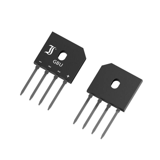
引脚分配:文档未提供具体的引脚分配信息。
参数特性:
- 最大交流输入电压:GBU10A为35V,GBU10M为700V
- 重复峰值反向电压:根据型号不同,从50V至1000V不等
- 最大整流输出电流:在自由站立条件下,GBU10A为7.0A,GBU10M为10.0A
- 存储温度范围:-50°C至+150°C
- 封装材料:UL 94V-0
- 焊接和组装条件:260°C/10s
功能详解:
- 器件符合RoHS、REACH和冲突矿产标准
- 可以独立放置或安装在散热器上
应用信息:适用于需要高电流整流的应用,例如主电网整流和电源供应。
封装信息:封装材料为UL 94V-0,器件可以散装在纸板托盘或封装在管中出售。