Specification No.:
Product Specification for Reference Only
( Preliminary )
Issued Date: July, 2013
Rev. : 1.01
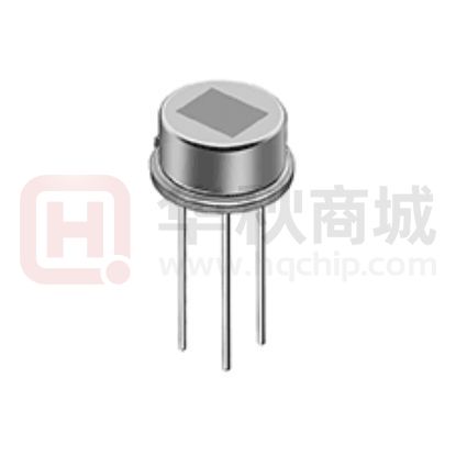
P a r t D e s c r i p t i o n : P yroelectric infrared sensor
焦電型赤外線センサ
MURATA Part No.:
村田品番
.:
IRA-S210ST01
IRA-S210ST01
The product specification in this sheet is for reference only.
The contents of this specification is subject to change.
この仕様書は参考図です。
この仕様書の内容は変更される場合があります。
You are requested to receive the latest specification and to return one
copy of the specification to us with your receipt signature before going
into mass production.
量産の際には、署名していただいた納入仕様書一部を返却していただきます。
Product Promotion Section 2
Sensor Products Department 1
Sensor Products Division
Murata MFG. Co.,Ltd.
�Specification No.:
焦電型赤外線センサ
IRA-S210ST01
Pyroelectric infrared sensor
Date
1,July,2013
P.2/8
暫定納入仕様書案
Product specification
承認
確認
作成
Approved by
Checked by
Prepared by
1. 適用 Scope
この納入仕様書は、人感赤外線検知に使用されるデュアルタイプ焦電型赤外線センサ
IRA-S210ST01 について規定します。この用途以外にご使用の場合には事前に弊社へ
ご連絡下さい。
This product specification is applied to a dual element type pyroelectric infrared sensor
IRA-S210ST01 used to detect infrared ray.
Please contact us when using this product for any other applications than described in the above.
2. 弊社品番 Murata Part Number
IRA-S210ST01
3. 外観 Outline Drawing and Dimensions
3-1 形状および寸法
Outline Dimensions
B C D
光学フィルタ/ Optical Filter
焦電素子/ Pyro-Element
A
E
F
H
G
I
d
s
g
Notes)
1. ニッケルメッキ
Nickel-plated on stem
2. J is specified on bottom of stem
3-2 受光電極配置及び寸法 Pyroelectric Element
2.0
1.0 1.0 1.0
(mm)
Symbol
A
B
C
D
E
F
G
H
I
Dimension
4.7±0.1mm
3.7±0.1mm
8.10.2mm
9.20.2mm
3.50.2mm
4.70.2mm
0.450.05mm
13.52mm
5.080.05mm
Symbol
d (Drain)
s (Source)
g (Ground)
Description
Supply voltage
Output
Ground
�Specification No.:
3-3 内部回路構成 Equivalent Circuit
d
s
(RG)
g
4. 表示 Numbering
製品側面に印字します。
It has a marking on a side of the sensor.
D01XXXXXX
D01
XXXXXX
: Model code
: Internal control number
5. 定格 (指定なき場合は25℃、50%RH時とします。)
Ratings and Characteristics (25C, 50%RH)
5-1 電圧感度 Responsivity (Rv)
Min.
Typ.
電圧感度Responsivity
3.6mVpp
4.6mVpp
(Rv)
ただし、電圧感度の測定は以下の測定器構成で行います。
Responsivity is measured with following system.
ロックアンプ 1Hz
Lock-in Amp. 1Hz
140mm
黒体炉
+5V
Black
Body
500K
d 47kΩ
s
g
メカニカルチョッパー1Hz
Mechanical Chopper 1Hz
22uF
赤外線センサ
Infrared Sensor
オシロスコープ
Oscilloscope
図2 電圧感度測定方法
Figure 1. Test system of responsivity
5-2 受光電極間感度差
Balance of Responsivity
受光電極感度差
Balance
10% 以下.
10% Max.
ただし、感度差(%)= | ( Rr-Rl ) / ( Rr+Rl ) | 100
Balance(%) = | ( Rr-Rl )/( Rr+Rl ) | 100
Rr : 右受光電極の感度
RI : 左受光電極の感度
Rr : Response from right element
Rl : Response from left element
P.3/8
�Specification No.:
P.4/8
5-3 ホワイトノイズ
White Noise Level
ホワイトノイズ
200mVpp 以下
White Noise
200mVpp Max.
測定条件 Conditions for measurement
・使用回路:図2測定回路を使用します。
Test circuit : With the circuit shown in figure2.
・測定点 :図2測定回路図中 OUT端子 GND端子間を測定します。
Measure Point : Across OUT and GND.
・記録
:ペンレコーダーで記録します。
Record : With Pen-recorder.
・指定環境 :シールボックス内、暗視野の状態で測定します。
Environment : In the electrically and optically shielded box kept at 25C.
LM78L05
100u
10n
33k
22u
47u
22n
33k
2.2meg
12VDC
1meg
33k
OUT
47u
d
s
A
A10k
g
1n
47k
10k LM358
1n
10k
22k
LM358
4.7k
1n
22u
GND
利得76.5 dB (6700倍)
Gain:76.5dB (x6700)
図2 測定回路
Figure 2. Test circuit
�Specification No.:
P.5/8
5-4 ソース電圧
Source Voltage
ソース電圧
(Vs)
0.2 to 2.5 V
Source voltage(Vs)
測定条件 Conditions for measurement
・使用回路: 5-3記載 図2 測定回路を使用します。
Test circuit : With the circuit shown in figure2.
・測定点:標準測定回路図中 A点 GND端子間
Measure Point : Across A and GND.
・測定環境:専用シールドボックスを用い、温度槽内にて測定します。
Environment : In the electrically and optically shielded and temperature controlled box.
5-5 立上がり時間 Warm-up Time
立上がり時間
30秒以下
Warm-up time
30sec. Max.
測定条件 Conditions for measurement
・使用回路: 5-3記載 図2 測定回路を使用します。
Test circuit : With the circuit shown in figure2.
・測定環境:専用シールドボックス内、暗視野の状態で測定します。
ただし、通電後、ソース電圧が規定値内に達するまでを立上がり時間とします。
Environment : In the electrically and optically shielded box kept at 25C.
Warm-up time is defined as time for Source Voltage to reach to specified value
from turning on.
5-6 電源電圧 Supply Voltage Range
2.0 to 15.0 VDC
5-7 推奨ソース抵抗範囲 Recommendable Rs Value
47kΩ ≦ Rs ≦ 200kΩ
ただしソース抵抗Rsは、S端子、GND端子間抵抗とします。
Resistance Rs is inserted across terminal-S and GND.
5-8 標準視野角 Field of View
45deg.
45deg.
図3 標準視野角
Figure3. Field of View
�Specification No.:
5-9 干渉フィルター Optical Filter
透過率 :以下の特性によります
Transmittance : See the graph shown in figure4.
基板材質:シリコン
Material : Single crystal silicon
基板厚さ:0.50±0.05mm
Thickness : 0.50 ± 0.05mm
3.0
(%)
100
4.0
5.0
6.0
7.0
8.0
10.0
12.0 (µm)
Transmittance
80
60
40
20
0
4000 3500 3000 2500 2000 1800 1600 1400 1200 1000 800 (cm -1 )
Wave number
図4 赤外線透過特性(例)
Figure4. Transmittance of optical filter (example)
6.使用温度範囲
Operating Temperature
-40 to 70 C
7.使用温度範囲
-40 to 85 C
Storage Temperature
P.6/8
�Specification No.:
8. 梱包・表示
P.7/8
Package and Marking
1号トムソン箱を使用して、図(A)のように100個/1箱で梱包し図(B)のように外箱に表示します。
100 pieces sensors are packed in a unit box as shown in (A).
Marking is on the box as per (B).
トムソン箱
Unit box
段ボール
Cardboard
導電性スポンジ
Conductive sponge
(A)
IRA-S210ST01
Inspection lot No.
100pcs
(B)
�Specification No.:
P.8/8
9. 信頼性 Reliability
9-1項から9-7項までの試験を実施します。常温にて 3時間 以上放置してから測定したとき、表1の判定基
準を満足します。
Judgment criteria for 9-1 to 9-7. After each one of the test, the sensor is kept for three hours at room
temperature, then it is evaluated with the following criteria.
項目
Items
外観
External appearance
感度
Responsivity
ノイズ
White noise
ソース電圧
Source voltage
判定基準
Judgment criteria
著しい損傷がありません。
No significant damage
初期値に対して変化率20%以内です。
Within ±20% shift from initial value
初期値+100mV以下です。
within initial value +100mV
規格範囲内です。
within rated value
表1 判定基準
Table 1. Judgment criteria
9-1
高温放置試験 High temperature
周囲温度 100℃、500時間経過後、常温にて 3時間 放置後測定します。
100C for 500hours
9-2 低温放置試験 Low temperature
周囲温度 -40℃、500時間経過後、常温にて 3時間放置後測定します。
-40C for 500hours
9-3
高温湿中放置試験 Humidity
周囲温度 60℃、湿度 95%RHで 500時間経過後、常温にて 3時間 放置後測定します。
60C, 95%RH for 500hours
9-4
熱サイクル試験 Heat cycle
-25℃、30分 → 常温、30分 → 55℃、30分 を 1サイクルとして、20回繰り返します。
その後、常温にて 3時間 放置後測定します。
20 times of the following cycle
-25C, 30min. Room temp. 30min. 55C, 30min. Room temp.
9-5
振動試験 Vibration
振動周波数 10~55Hz、全振幅 1.5mmの振動を、X,Y,Zの 3方向に各々 60分加えます。
その後、常温にて 3時間 放置後測定します。
Apply vibration of amplitude of 1.5mm with 10 to 55Hz bands to each of 3 perpendicular
directions (x, y, z) for an hour.
9-6
衝撃試験 Shock
標準衝撃試験機にて、100Gの加速度を、X,Y,Zの 3方向に加えます。その後、常温にて 3時間
放置後測定します。(1G=9.8m/s2)
Apply shock of 100G sinewave by standard shock tester to each 3 perpendicular
directions (x, y, z). (1G=9.8m/s2)
9-7 はんだ耐熱性 Soldering heat
温度 260±5℃のはんだ槽に、端子根元 3mmの位置まで 10±1秒間浸します。
その後、常温にて 3時間 放置後測定します。
Immerse up to 3mm from the bottom of stem in solder bath of 2605C for 101sec..
�Specification No.:
9-8
P.9/8
密閉試験(グロスリークテスト)Hermetic sealing
MIL-STD-202F、試験方法 112D、試験条件 Dに準じます。
温度 125±5℃の フロロカーボン液(FC-40)に 20秒間浸します。
このとき、気泡が発生しません。
Conform to MIL-STD-202F chapter 112D, condition D.
Immerse in fluorocarbon bath (FC-40) of 1255C for 20sec..
There should be no generation of bubbles.
9-10
はんだ付性
MIL-STD-202F、試験方法 208Bに準じます。
ロジン系フラックスに浸した後、温度 230±5℃のはんだ槽に、端子根元 2~2.5mmの位置まで
5±0.5秒間浸します。
このとき、端子には 95%以上はんだが付着します。
Conform to MIL-STD-202F chapter 208B.
Terminal immerse the Rosin flux after immerse in fluorocarbon bath of 2305C for 5sec ±
0.5sec when a solder attaches to a terminal more than 95%.
10.
注意
Caution
10-1用途の限定 Limitation of Applications
当製品について、その故障や誤動作が人命または財産に危害を及ぼす恐れがある等の理由により、
高信頼性が要求される以下の用途では使用しないで下さい。
万一、購入者側の責任で以下の用途に当製品を使用された場合、当社はいかなる責も負いかねますの
でご了承ください。
Please avoid using this product for the applications listed below which require especially high reliability
for the prevention of defects that might directly cause damage to the third party's life, body or property.
When this product is used for the applications listed below, we shall not be liable for any claims on the
product.
①航空機器 ②宇宙機器 ③海底機器 ④発電所制御機器 ⑤医療機器
⑥輸送機器(自動車、列車、船舶等) ⑦交通用信号機器
⑧情報処理機器 ⑨その他上記機器と同等の機器
1. Aircraft equipment
2. Aerospace equipment
3. Undersea equipment
4. Power plant control equipment
5. Medical equipment
6. Transportation equipment (vehicles, trains, ships, etc.)
7. Traffic signal equipment
8. Data-processing equipment
9. Application of similar complexity and/or reliability requirement to the applications listed in the above
10-2 フェールセーフ機能の付加 Fail-safe
当製品に万が一異常や不具合が生じた場合でも、二次災害防止のために完成品に適切なフェー
ルセーフ機能を必ず付加して下さい。
Be sure to provide an appropriate fail-safe function on your product to prevent a second damage
that may be caused by the abnormal function or the failure of our product.
�Specification No.:
11. 使用上の注意
P.10/8
Caution in use
11-1 設計時
11-1 Notice in design
1) 屋外で使用される場合や、防水性を要求されるような環境で使用される場合は、適切な光学フ
ィルターの設置、防水構造の採用、及び、結露対策等を十分施して下さい。誤動作や、回路シ
ョート等の原因となります。
In the case of outdoor use, suitable optical filter and water and humidity proof structure should be
applied.
2) 電源には安定化電源を使用して下さい。
To prevent failure or malfunction, Please use a stabilized power supply.
3) 誤動作や動作しないことが予想されますので、下記のような状態ではご使用しないでください。
Please avoid using the sensor in the following conditions because it may cause failure or
malfunction ;
a) 液 体 中 ( 水 、 有 機 溶 媒 等 ) や 腐 蝕 性 ガ ス ( 亜 硫 酸 ガ ス 、 窒 素 酸 化 ガ ス 等 )
及び、潮風中での使用。
In such a fluid as water, alcohol etc. corrosive gas (S02, Cl2, NOX etc.) or sea breeze.
b) 高湿下での連続使用。
In high humidity.
c) 太陽光、自動車のヘッドライト等の直射を受ける場所での使用。
In a place exposed directly to sunlight or headlight of automobile.
d) 急激な温度変化がある場所での使用。
In a place exposed to rapid ambient temperature change.
e) 温風ヒーター、エアコン等の送風を直接受ける場所での使用。
In a place exposed directly to blow from air-conditioner or heater.
f) 強い振動がある場所での使用。
In a place exposed to strong vibration.
g) 強い電磁波がある場所での使用。
In a place exposed to strong electromagnetic field.
h) 当センサの検知エリア内に赤外線を透さない障害物(ガラスや壁等)がある場所での使用。
In such a place where infrared ray is shaded.
i) 帯電、静電気が発生する場所での使用。
In such a place are charge field and static electricity field.
j) その他、上記a)~h)項に準じる場所での使用。
In any other place similar to the above (a) through (h).
�Specification No.:
P.11/8
11-2 保管および使用時 Notice in handling and storage
1) 当センサの光学フィルタを汚したり、傷をつけないで下さい。
Optical filter of sensor should not be scratched or soiled.
2) センサ本体、および、端子部に強い衝撃を与えないで下さい。
Strong shock should be avoided.
3) 静電気や、電磁波の環境下では誤動作する可能性があります。
十分ご評価の上、ご使用ください。
It may malfunction under electrostatics and electromagnetic field. Please use it after enough
evaluating.
4) 静電気や、強い電磁波等のある場所で保管しないで下さい。
Electrostatics and strong electromagnetic field should be avoided.
5) 端子を、導電性スポンジから外した状態で保管しないで下さい。
Sensor should be kept on conductive sponge
6) 高温、多湿、塵埃の多い場所、液体中(水、有機溶媒等)、腐蝕性ガス(亜硫酸ガス、窒素
酸化物ガス等)及び、潮風の存在する場所で保管しないで下さい。
High temperature, high humidity, fluid as water or alcohol etc., corrosive gas ( S0 2, Cl2, NOX
etc.) and sea breeze should be avoided.
7) 保管環境は、周囲温度-10~40℃、相対湿度15~95%とし、納入後6ヶ月以内にご使用くださ
い。
Store the products where the temperature and relative humidity do not exceed -10 to 40
degrees centigrade, and 30 to 80%RH. Use the products within 6 months after receiving.
11-3 実装時 Notice in mounting
1) はんだ付け Soldering
i) 端子のはんだ付けは、こて先はんだで行って下さい。
Please perform the soldering of the terminal with an iron point solder.
ii) 端子のはんだ付けは、できるだけすばやく行って下さい。具体的には下記の範囲で行っ
てください。
Please mount the soldering of the terminal as quick as possible. Specifically, please go in the
range of follows.
はんだのこて先温度:350℃
iron point temperature : 350 degree C
端子根元からの長さ
時間
Terminal length from stem
time
1 ~ 3mm
1ヶ所につき 3秒以内
Less than 3sec by a terminal
3mm以上
1ヶ所につき 10秒以内
Over 3mm
Less than 3sec by a terminal
iii) フラックスは、塩素含有率 0.2wt%以下の水溶性のものをご使用下さい。
The flux use a water-soluble thing less than chlorine content 0.2% by weight.
尚、はんだ付け後のフラックスは、完全に除去して下さい。不十分な場合は、誤動作等の原
因となります。
Please completely remove the flux after the soldering. When you are insufficient, it causes the
malfunction.
2) 洗浄 Cleaning
洗浄は、ブラシ洗浄を行ってください。これ以外の洗浄方法では、受光部の汚れやリーク不
良等により、誤動作等の原因となります。
Please use the cleaning of brush. By the cleaning method except this, it causes the malfunction
by poor dirt and leak of the light receiving department.
2) 当製品は、一度でも限度を超えた高温状態になると、特性を失い機能しなくなります。当納入仕
�Specification No.:
P.12/8
様書記載の条件を越えた温度が加わらないように実装して下さい。
Please follow soldering conditions described in the specification. This product can permanently
stop operating if the piezoelectric(pyroelectric) characteristic is decreased due to excessive
heating.
12.
お願いNote
ご使用に際しては、貴社製品に実装された状態で必ず評価して下さい。
1) 当製品を当納入仕様書の記載内容を逸脱して使用しないで下さい。
Please make sure that your product has been evaluated in view of your specifications with
our product being mounted to your product.
2) 当製品を当納入仕様書の記載内容を逸脱して使用しないで下さい。
You are requested not to use our product deviating from the agreed specifications.
3) 弊社は、仕様書、図面その他の技術資料には、取引に関する契約事項を記載することは
適切ではないものと存じております。従って、もし、貴社が作成されたこれら技術資料
に、品質保証、PL、工業所有権等にかかる弊社の責任の範囲に関する記載がある場合
は、当該記載は無効とさせていただきます。これらの事項につきましては、別途取引基
本契約書等においてお申し越しいただきたくお願いします
We consider it not to appropriate to include any terms and conditions with regard to the
business transaction in the product specifications, drawings or other technical documents.
Therefore, if your technical documents as above include such terms and conditions such
as warranty clause, product liability clause, or intellectual property infringement liability
clause, they will be deemed to be invalid.
�
很抱歉,暂时无法提供与“IRA-S210ST01”相匹配的价格&库存,您可以联系我们找货
免费人工找货- 国内价格
- 1+13.90500
- 10+13.39000
- 100+11.84500
- 500+11.53600