AQY210LS
TESTING
GU (General Use) Type SOP Series 1-Channel (Form A) Current Limit Function 4-Pin Type FEATURES
4.3 .169 4.4 .173 2.1 .083
PhotoMOS RELAYS
(6-pin) Volume (4-pin) Approx. 70%
mm inch
1
4
2
3
1. Current Limit Function To control an over current from flowing, the current limit function has been realized. It keeps an output current at a constant value when the current reaches a specified current limit value. 2. Enhancing the capability of surge resistance between output terminals The current limit function controls the ON time surge current to enhance the capability of surge resistance between output terminals. 3. SO package 4-Pin type in super miniature design The device comes in a super-miniature SO package 4-Pin type measuring (W) 4.3×(L) 4.4×(H) 2.1 mm (W) .169×(L) .173×(H) .083 inch—approx. 70% of the volume and 70% of the footprint size of SO package 6-pin type PhotoMOS Relays.
Approx. 70% Footprint
4. Tape and reel The device comes standard in a tape and reel (1,000 pcs./reel) to facilitate automatic insertion machines. 4. Controls low-level analog signals 5. Low-level off state leakage current
TYPICAL APPLICATIONS
• Telephone equipment • Modem
TYPES
Output rating* Type AC/DC type Load voltage 350 V Load current 120 mA Picked from the 1/2-pin side 1 Form A AQY210LSX Part No. Picked from the 3/4-pin side 1 Form A AQY210LSZ Packing quantity in tape and reel 1,000 pcs.
* Indicate the peak AC and DC values. Notes: (1) Tape package is the standard packing style. Also available in tube. (Part No. suffix "X" or "Z" is not needed when ordering; Tube: 100 pcs.; Case: 2,000 pcs.) (2) For space reasons, the initial letters of the product number "AQY" and "S" are ommited on the product seal. The package type indicator "X" and "Z" are omitted from the seal. (Ex. the label for product number AQY210LS is 210L).
RATING
1. Absolute maximum ratings (Ambient temperature: 25°C 77°F)
Item LED forward current LED reverse voltage Input Peak forward current Power dissipation Load voltage (peak AC) Output Continuous load current Power dissipation Total power dissipation I/O isolatiom voltage Operating Temperature limits Storage Symbol IF VR IFP Pin VL IL Pout PT Viso Topr Tstg AQY210LS 50 mA 3V 1A 75 mW 350 V 0.12 A 350 mW 400 mW 1,500 V AC –40°C to +85°C –40°F to +185°F –40°C to +100°C –40°F to +212°F Remarks
f = 100 Hz, Duty factor = 0.1%
Non-condensing at low temperatures
101
�AQY210LS
2. Electrical characteristics (Ambient temperature: 25°C 77°F)
Item LED operate current Input LED turn off current LED dropout voltage On resistance Output Off state leakage current Current limit Typical Maximum Minimum Typical Minimum Typical Typical Maximum Maximum Symbol IFon IFoff VF Ron ILeak — Ton Toff Ciso Riso AQY210LS 0.9 mA 3 mA 0.4 mA 0.85 mA 1.14 (1.25 V at IF = 50mA) 1.5 V 20Ω 25Ω 1µA 0.18 A 0.3 ms 2.0 ms 0.05 ms 1.0 ms 0.8 pF 1.5 pF 1,000 MΩ Condition IL = Max. IL = Max. IF = 5 mA IF = 5 mA IL = Max. Within 1 s on time IF = 0 VL = Max. IF = 5 mA IF = 5 mA IL = Max. IF = 5 mA IL = Max. f = 1 MHz VB = 0 500 V DC For type of connection, see page 31. *Turn on/Turn off time
Typical Typical Turn on time* Maximum Typical Turn off time* Transfer charMaximum acteristics Typical I/O capacitance Maximum Initial I/O isolaMinimum tion resistance
Note: Recommendable LED forward current IF= 5 mA.
Input
90% Output Ton Toff 10%
s For Dimensions, see Page 28. s For Schematic and Wiring Diagrams, see Page 31. s For Cautions for Use, see Page 36.
REFERENCE DATA
1. Load current vs. ambient temperature characteristics
Allowable ambient temperature: –40°C to +85°C –40°F to +185°F
140 120 On resistance, Ω Load current, mA 100 80 60 40 10 20 0 –40 –20 0 20 40 60 80 85 100 Ambient temperature, °C 0 –40 –20 0 20 40 60 80 85 Ambient temperature, °C 0.5 0
2. On resistance vs. ambient temperature characteristics
Measured portion: between terminals 3 and 4; LED current: 5 mA; Load voltage: Max. (DC) Continuous load current: Max.(DC)
50
3. Turn on time vs. ambient temperature characteristics
LED current: 5 mA; Load voltage: Max.(DC); Continuous load current: Max.(DC)
3.0 2.5 Turn on time, ms 2.0 1.5 1.0
40
30
20
–40 –20
0
20
40
60
80 85
Ambient temperature, °C
102
�AQY210LS
4. Turn off time vs. ambient temperature characteristics
LED current: 5 mA; Load voltage: Max.(DC); Continuous load current: Max.(DC)
0.5 LED operate current, mA
5. LED operate current vs. ambient temperature characteristics
Load voltage: Max.(DC); Continuous load current: Max.(DC)
5
6. LED turn off current vs. ambient temperature characteristics
Load voltage: Max.(DC); Continuous load current: Max.(DC)
5 LED turn off current, mA
Turn off time, ms
0.4
4
4
0.3
3
3
0.2
2
2
0.1
1
1
0
–40
–20
0
20
40
60
80 85
0
–40 –20
0
20
40
60
80 85
0
–40 –20
0
20
40
60
80 85
Ambient temperature, °C
Ambient temperature, °C
Ambient temperature, °C
7. LED dropout voltage vs. ambient temperature characteristics
LED current: 5 to 50 mA
1.5
8. Voltage vs. current characteristics of output at MOS portion
Measured portion: between terminals 3 and 4; Ambient temperature: 25°C 77°F
Current, mA 100 80 60 40
9. Off state leakage current
Measured portion: between terminals 3 and 4; Ambient temperature: 25°C 77°F
1.4 1.3 1.2 1.1 1.0 0 50mA 30mA 20mA 10mA 5mA
20 –5 –4 –3 –2 –1 12345 –20 Voltage, V –40 –60 –80 –100 –40 –20 0 20 40 60 80 85 Ambient temperature, °C
Off state leakage current, A
LED dropout voltage, V
10 –3
10 –6
10 –9
10 –12 0 20 40 60 80 Load voltage, V 100
10. LED forward current vs. turn on time characteristics
Measured portion: between terminals 3 and 4; Load voltage: Max.(DC); Continuous load current: Max.(DC); Ambient temperature: 25°C 77°F
1.2 1.0 Turn on time, ms
11. LED forward current vs. turn off time characteristics
Measured portion: between terminals 3 and 4; Load voltage: Max.(DC); Continuous load current: Max.(DC); Ambient temperature: 25°C 77°F
0.12 0.10 Turn off time, ms 0.08 0.06 0.04 0.02 0
12. Applied voltage vs. output capacitance characteristics
Measured portion: between terminals 3 and 4; Frequency: 1 MHz; Ambient temperature: 25°C 77°F
200 Output capacitance, pF
150
0.8 0.6 0.4 0.2 0
100
50
0
10
20
30
40
50
60
0
10
20
30
40
50
60
0
0
10
20
30
40
50
LED forward current, mA
LED forward current, mA
Applied voltage, V
What is current limit
When a load current reaches the specified output control current, a current limit function works against the load current to keep the current a constant value. The current limit circuit built into the PhotoMOS relay thus controls the instantaneous load current to effectively ensure circuit safety. This safety feature protects circuits downstream of the PhotoMOS relay against over-current. But, if the current-limiting feature is used longer than the specified time, the PhotoMOS relay can be destroyed. Therefore, set the output loss to the max. rate or less. • Comparison of output voltage and output current characteristics V-I Characteristics
Output current
Output voltage
5/7/2001
All Rights Reserved, © Copyright Matsushita Electric Works, 103 Ltd. Go To Online Catalog
�
很抱歉,暂时无法提供与“AQY210LS”相匹配的价格&库存,您可以联系我们找货
免费人工找货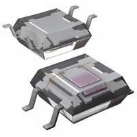


 工商网监
湘ICP备2023018690号
工商网监
湘ICP备2023018690号
