DC 3-wire Cylindrical Inductive Proximity Sensor
Amplifier Built-in
Oil resistant Metal embedding
possible
GXL
INDUCTIVE
PROXIMITY SENSORS
GX-N SERIES
GX-U/FU
GL-18H/18HL
GL-N12
Amplifier Built-in
GL-8/8U
GL-6
High performance and
environmental
resistance at low price
Robust in tightening
Long sensing range
Cost effective
The tightening torque has been improved to approx. four times greater
than that of conventional models
because of its thick case. As the
sensor can be securely tightened, it
does not get loose due to vibration or
shock.
The GX-N series features 1.6 times
longer sensing range than conventional models. Setting with enough margin
is possible.
It combines high reliability with cost
effectiveness.
Conventional
GX-18M(B) model
GX-N12ML(B)
8 mm
0.315 in
GX-N18M(B)
s
19.6 N䡠m or less 4 times approx. 80 N䡠m or less
1.6
GX-N
GX-12ML(B)
time
Conventional model
5 mm
0.197 in
The operation indicator (orange) is
easily observable from any direction
since it is housed in the transparent tail
section, which lights up brightly.
GA-10/GH
Amplifier-separated
GX
Visible operation indicator
Operation indicator
(Orange)
736
Ramco Innovations - 1207 Maple Street, West Des Moines IA USA 50265 - 800-280-6933 - www.ramcoinnovations.com
�APPLICATIONS
Controlling depth of drilling
Detecting workpiece in robot hand
By detecting the
dog, the sensor
decides the depth
of the drilled hole.
It can reliably detect even
aluminum pallets because
of its long sensing range.
It checks handling
by the robot.
GL-6
GXL
Detecting traveling aluminum pallets
INDUCTIVE
PROXIMITY SENSORS
GX-N
Shielded type
M12
40.5
1.594
(0 to 2.4 mm 0 to 0.094 in)
Stable sensing range
7 mm 0.276 in
M18
41.5
1.634
(0 to 5.6 mm 0 to 0.220 in)
10 mm 0.394 in
M30
44.5
1.752
40.5
1.594
15 mm 0.591 in
M18
41.5
1.634
(0 to 12 mm 0 to 0.472 in)
22 mm 0.866 in
M30
44.5
1.752
Normally open
GX-N12MB
Normally closed
GX-N18M
Normally open
GX-N18MB
Normally closed
GX-N30M
Normally open
GX-N12ML
(0 to 6.4 mm 0 to 0.252 in)
(0 to 17.6 mm 0 to 0.693 in)
Output operation
GX-N12M
GX-N30MB
8 mm 0.315 in
M12
Non-shielded type
(0 to 8 mm 0 to 0.315 in)
Output
NPN
open-collector
transistor
Normally closed
GX-U/FU
Maximum operation distance
3 mm 0.118 in
Model No.
Normally open
GX-N12MLB
Normally closed
GX-N18ML
Normally open
GX-N18MLB
Normally closed
GX-N30ML
Normally open
GX-N30MLB
Normally closed
GX-N
Sensing range (Note)
GX
Appearance (mm in)
Amplifier Built-in
GL-18H/18HL
GL-N12
Type
GL-8/8U
ORDER GUIDE
Amplifier-separated
GA-10/GH
Note: The maximum operation distance stands for the maximum distance for which the sensor can detect the standard sensing object.
The stable sensing range stands for the sensing range for which the sensor can stably detect the standard sensing object even if
there is an ambient temperature drift and/or supply voltage fluctuation.
Ramco Innovations - 1207 Maple Street, West Des Moines IA USA 50265 - 800-280-6933 - www.ramcoinnovations.com
737
�INDUCTIVE
PROXIMITY SENSORS
GX-N
ORDER GUIDE
5 m 16.404 ft cable length type
5 m 16.404 ft cable length type (standard: 2 m 6.562 ft) is also available.
GL-18H/18HL
GL-N12
Amplifier Built-in
Shielded type
Type
Non-shielded type
GL-8/8U
GL-6
GXL
• Table of Model Nos.
Standard
5 m 16.404 ft cable length type
GX-N12M
GX-N12M-C5
GX-N12MB
GX-N12MB-C5
GX-N18M
GX-N18M-C5
GX-N18MB
GX-N18MB-C5
GX-N30M
GX-N30M-C5
GX-N30MB
GX-N30MB-C5
GX-N12ML
GX-N12ML-C5
GX-N12MLB
GX-N12MLB-C5
GX-N18ML
GX-N18ML-C5
GX-N18MLB
GX-N18MLB-C5
GX-N30ML
GX-N30ML-C5
GX-N30MLB
GX-N30MLB-C5
OPTIONS
Protection cover
Designation
Description
MS-H12
For GX-N12M(B)
MS-H18
For GX-N18M(B)
MS-H30
For GX-N30M(B)
It protects the sensing surface from welding sparks
(spatter), etc.
• MS-H12
• MS-H18
• MS-H30
GA-10/GH
Amplifier-separated
GX
GX-N
GX-U/FU
Protection cover
Model No.
738
Ramco Innovations - 1207 Maple Street, West Des Moines IA USA 50265 - 800-280-6933 - www.ramcoinnovations.com
�SPECIFICATIONS
Type
Item
Shielded type
Non-shielded type
Model No. GX-N12M GX-N12MB GX-N18M GX-N18MB GX-N30M GX-N30MB GX-N12ML GX-N12MLB GX-N18ML GX-N18MLB GX-N30ML GX-N30MLB
INDUCTIVE
PROXIMITY SENSORS
GX-N
Stable sensing range (Note 1)
0 to 2.4 mm 0 to 0.094 in 0 to 5.6 mm 0 to 0.220 in 0 to 8 mm 0 to 0.315 in 0 to 6.4 mm 0 to 0.252 in 0 to 12 mm 0 to 0.472 in 0 to 17.6 mm 0 to 0.693 in
Standard sensing object
Iron sheet 12�12�t 1 mm Iron sheet 18�18�t 1 mm Iron sheet 30�30�t 1 mm Iron sheet 30�30�t 1 mm Iron sheet 50�50�t 1 mm Iron sheet 70�70�t 1 mm
0.472�0.472�t 0.039 in 0.709�0.709�t 0.039 in 1.181�1.181�t 0.039 in 1.181�1.181�t 0.039 in 1.969�1.969�t 0.039 in 2.756�2.756�t 0.039 in
Hysteresis
20 % or less of operation distance
10 mA or less
NPN open-collector transistor
• Maximum sink current: 100 mA
• Applied voltage: 30 V DC or less (between output and 0 V)
• Residual voltage: 1.5 V or less (at 100 mA sink current)
0.4 V or less (at 16 mA sink current)
Output
Output operation
Normally open Normally closed Normally open Normally closed Normally open Normally closed Normally open Normally closed Normally open Normally closed Normally open Normally closed
Short-circuit protection
Incorporated
Max. response frequency
450 Hz
300 Hz
300 Hz
Operation indicator
350 Hz
100 Hz
100 Hz
GL-8/8U
Current consumption
GL-6
10
12 to 24 V DC �
�15 % Ripple P-P 10 % or less
Supply voltage
IP67 (IEC), IP67g (JEM)
�25 to�70 �C �13 to�158 �F, Storage:�30 to�80 �C �22 to�176 �F
Ambient humidity
45 to 85 % RH, Storage: 35 to 95 % RH
Noise immunity
Power line: 240 Vp, 0.5 !s pulse width (with noise simulator)
Voltage withstandability
1,000 V AC for one min. between all supply terminals connected together and enclosure
Insulation resistance
50 MΩ, or more, with 250 V DC megger between all supply terminals connected together and enclosure
Vibration resistance
10 to 55 Hz frequency, 1.5 mm 0.059 in amplitude in X, Y and Z directions for two hours each
1,000 m/s2 acceleration (100 G approx.) in X, Y and Z directions for three times each
Shock resistance
Over ambient temperature range �25 to�70 �C �13 to�158 �F: Within�10 % of sensing range at �20 �C �68 �F
Within�2 % for�10 % fluctuation of the supply voltage
Material
Enclosure: Brass (Nickel plated), Sensing part: Nylon, Indicator part: Nylon
Cable
0.3 mm2 3-core oil, heat and cold resistant cabtyre cable, 2 m 6.562 ft long
GX-U/FU
Sensing range Temperature characteristics
variation
Voltage characteristics
Extension up to total 100 m 328.084 ft is possible with 0.3 mm2, or more, cable.
Cable extension
Weight (Note 2)
65 g approx.
110 g approx.
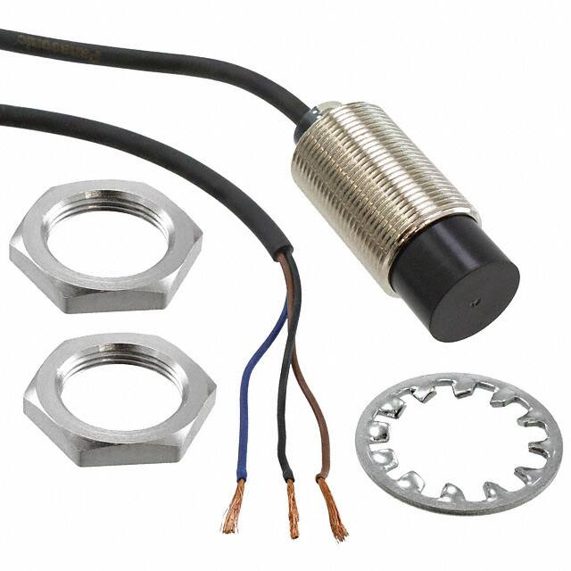
Accessories
240 g approx.
65 g approx.
110 g approx.
240 g approx.
Nut: 2 pcs., Toothed lock washer: 1 pc.
Notes: 1) The maximum operation distance stands for the maximum distance for which the sensor can detect the standard sensing object.
The stable sensing range stands for the sensing range for which the sensor can stably detect the standard sensing object even if there is an ambient
temperature drift and/or supply voltage fluctuation.
Notes: 2) The given weight includes the weight of two nuts and one toothed lock washer.
GX-N
Ambient temperature
Amplifier Built-in
GL-18H/18HL
GL-N12
Orange LED (lights up when the output is ON)
Protection
Environmental resistance
GXL
Max. operation distance (Note 1) 3 mm 0.118 in�10 % 7 mm 0.276 in�10 % 10 mm 0.394 in�10 % 8 mm 0.315 in�10 % 15 mm 0.591 in�10 % 22 mm 0.866 in �10 %
I/O circuit diagram
Wiring diagram
Sensor circuit
(Brown)�V
Load
Black
D
Load
(Black) Output (Note)
ZD
100 mA max.
�
�
12 to 24 V DC
�10 %
�15
� 12 to 24 V DC
10
� �
�15 %
Blue
(Blue) 0 V
Internal circuit
Users’ circuit
Note: If a capacitive load is directly connected to the output, malfunction
may occur.
Symbols ... D : Reverse supply polarity protection diode
ZD: Surge absorption zener diode
Tr : NPN output transistor
Ramco Innovations - 1207 Maple Street, West Des Moines IA USA 50265 - 800-280-6933 - www.ramcoinnovations.com
739
Amplifier-separated
GA-10/GH
Brown
Color code
Tr
GX
I/O CIRCUIT AND WIRING DIAGRAMS
�SENSING CHARACTERISTICS (TYPICAL)
GX-N12M
GX-N12MB
Brass
Aluminum
2
0
2
4
0.079
0.079
0.157
Center
Left
Right
Operating point #(mm in)
0
10
20
30
0.394
0.787
1.181
Sensing object side
length a (mm in)
40
1.575
GX-N18M
GX-N18MB
Standard sensing object
Iron sheet 18�18�t 1 mm 0.709�0.709�t 0.039 in
#
10
L
0.394
5
0.197
Correlation between sensing object size and sensing range
As the sensing object size becomes smaller than
Sensing object a�a mm a�a in
the standard size (iron sheet 18�18�t 1 mm
t 1 mm
10 L
t 0.039 in
0.709� 0.709� t 0.039 in), the sensing range
0.394
shortens as shown in the left figure.
Sensing range L (mm in)
Setting distance L (mm in)
Sensing field
Iron
Stainless steel
(SUS304)
5
0.197
0
20
0.787
10
0
10
20
0.394
0.394
0.787
Center
Left
Right
Operating point #(mm in)
Brass
Aluminum
0
10
20
30
0.394 0.787
1.181
Sensing object side
length a (mm in)
40
1.575
GX-N30M
GX-N30MB
Standard sensing object
Iron sheet 30�30�t 1 mm 1.181�1.181�t 0.039 in
#
10
L
0.394
5
0.197
GX
20
0.787
Correlation between sensing object size and sensing range
As the sensing object size becomes smaller than
the standard size (iron sheet 30�30�t 1 mm
Iron
10
1.181� 1.181� t 0.039 in), the sensing range
0.394
shortens as shown in the left figure.
Stainless steel
Sensing range L (mm in)
Sensing field
0
(SUS304)
5
0.197
Brass
Sensing object a�a mm a�a in Aluminum
L
0
10
0
10
20
0.394
0.394
0.787
Center
Left
Right
Operating point #(mm in)
t 1 mm
t 0.039 in
20
40
60
0.787 1.575
2.362
Sensing object side
length a (mm in)
80
3.150
GX-N12ML
GX-N12MLB
Setting distance L (mm in)
Sensing field
GA-10/GH
Amplifier-separated
Stainless steel
(SUS304)
2
0.079
0
4
0.157
Setting distance L (mm in)
GX-N
GX-U/FU
GL-18H/18HL
GL-N12
Amplifier Built-in
GL-8/8U
GL-6
2
0.079
Correlation between sensing object size and sensing range
As the sensing object size becomes smaller than
Sensing object a�a mm a�a in
the standard size (iron sheet 12�12�t 1 mm
t
1
mm
4 L
t 0.039 in
0.472� 0.472� t 0.039 in), the sensing range
0.157
shortens as shown in the left figure.
Iron
Sensing range L (mm in)
Standard sensing object
Iron sheet 12�12�t 1 mm 0.472�0.472�t 0.039 in
#
4
L
0.157
Setting distance L (mm in)
GXL
Sensing field
Standard sensing object
Iron sheet 30�30�t 1 mm 1.181�1.181�t 0.039 in
#
10
L
0.394
740
Stainless steel
(SUS304)
5
0.197
5
0.197
0
20
0.787
Correlation between sensing object size and sensing range
As the sensing object size becomes smaller than
Sensing object a�a mm a�a in
t 1 mm
the standard size (iron sheet 30�30�t 1mm
L
t 0.039 in
10
1.181� 1.181� t 0.039 in), the sensing range
0.394
Iron
shortens as shown in the left figure.
Sensing range L (mm in)
INDUCTIVE
PROXIMITY SENSORS
GX-N
10
0
10
20
0.394
0.394
0.787
Center
Left
Right
Operating point #(mm in)
Brass
Aluminum
0
20
40
60
0.787
1.575
2.362
Sensing object side
length a (mm in)
80
3.150
Ramco Innovations - 1207 Maple Street, West Des Moines IA USA 50265 - 800-280-6933 - www.ramcoinnovations.com
�SENSING CHARACTERISTICS (TYPICAL)
GX-N18ML
GX-N18MLB
0
20
0.787
GXL
Iron
10
0.394
Brass
Aluminum
0
10
0
10
20
0.394
0.394
0.787
Center
Left
Right
Operating point #(mm in)
Stainless steel
(SUS304)
20
40
60
0.787 1.575
2.362
Sensing object side
length a (mm in)
GL-6
10
0.394
Correlation between sensing object size and sensing range
As the sensing object size becomes smaller than
Sensing object a�a mm a�a in
t 1 mm
the standard size (iron sheet 50�50�t 1 mm
L
t 0.039 in
20
1.969� 1.969� t 0.039 in), the sensing range
0.787
shortens as shown in the left figure.
80
3.150
GL-8/8U
Setting distance L (mm in)
Standard sensing object
Iron sheet 50�50�t 1 mm 1.969�1.969�t 0.039 in
#
20
L
0.787
Sensing range L (mm in)
Sensing field
GX-N30ML
GX-N30MLB
10
0.394 Standard sensing object
Iron sheet 70�70�t 1 mm 2.756�2.756�t 0.039 in
#
L
10
0
10
20
0.394
0.394
0.787
Center
Left
Right
Operating point #(mm in)
0
Brass
Sensing object a�a mm a�a in Aluminum
t 1 mm
L
t 0.039 in
20
40
60
0.787 1.575
2.362
Sensing object side
length a (mm in)
80
3.150
Amplifier-separated
GA-10/GH
GX
GX-N
GX-U/FU
0
20
0.787
10
0.394
Amplifier Built-in
GL-18H/18HL
GL-N12
20
0.787
Correlation between sensing object size and sensing range
As the sensing object size becomes smaller than
Iron
the standard size (iron sheet 70�70�t 1 mm
20
2.756� 2.756� t 0.039 in), the sensing range
0.787
Stainless steel
shortens as shown in the left figure.
(SUS304)
Sensing range L (mm in)
Setting distance L (mm in)
Sensing field
INDUCTIVE
PROXIMITY SENSORS
GX-N
Ramco Innovations - 1207 Maple Street, West Des Moines IA USA 50265 - 800-280-6933 - www.ramcoinnovations.com
741
�INDUCTIVE
PROXIMITY SENSORS
GXL
GX-N
PRECAUTIONS FOR PROPER USE
Refer to p.1152l for general precautions.
This product is not a safety sensor. Its use is not
intended or designed to protect life and prevent body
injury or property damage from dangerous parts of
machinery. It is a normal object detection sensor.
Face to face mounting
Mounting
• The tightening torque should be as given below.
Shielded type
GX-N12M(B)
GX-N18M(B)
Attached toothed
lock washer
Parallel mounting
GL-6
A
GX-N12ML(B)
GX-N18ML(B)
GL-8/8U
Model No.
Mounting plate
GX-N30ML(B)
Dimension A (mm in)
Tightening torque
3.5 to 13.5 0.138 to 0.531
10 N�m
13.5 0.531 or more
20 N�m
4 to 18 0.157 to 0.709
45 N�m
18 0.709 or more
80 N�m
5 to 21 0.197 to 0.827
80 N�m
GL-18H/18HL
GL-N12
Amplifier Built-in
GX-U/FU
15
0.591
35
1.378
55
2.165
70
2.756
125
4.921
190
7.480
Correction coefficient
Model No.
GX-N30M(B)
21 0.827 or more
180 N�m
GX-N12ML(B)
15 0.591 or more
20 N�m
Metal
GX-N18ML(B)
25 0.984 or more
80 N�m
Iron
GX-N12M(B) GX-N18M(B) GX-N30M(B) GX-N12ML(B) GX-N18ML(B) GX-N30ML(B)
1
1
1
1
1
1
Stainless steel
0.77 approx. 0.73 approx. 0.70 approx. 0.66 approx. 0.68 approx. 0.65 approx.
(SUS304)
180 N�m
30 1.181 or more
25
0.984
50
1.969
90
3.543
120
4.724
180
7.087
290
11.417
Sensing range
• The sensing range is specified for the standard sensing
object. With a non-ferrous metal, the sensing range is
obtained by multiplying with the correction coefficient
specified below.
GX-N12M(B)
GX-N30ML(B)
E (mm in) F (mm in)
E05H0236
GX-N18M(B)
Note: Mount such that the nuts do not protrude from the threaded portion.
Brass
0.52 approx. 0.50 approx. 0.45 approx. 0.44 approx. 0.46 approx. 0.44 approx.
Distance from surrounding metal
• As metal around the sensor may affect the sensing
performance, pay attention to the following points.
Aluminum
0.51 approx. 0.48 approx. 0.44 approx. 0.43 approx. 0.44 approx. 0.43 approx.
Influence of surrounding metal
• The surrounding metal will affect the sensing
performance. Keep the minimum distance specified in the
table below.
Model No.
GX-N12M(B)
Background metal
GX-N
GX-N30M(B)
F
Mounting plate
GX-N18M(B)
B
GX-N30M(B)
GX-N12ML(B)
GX
GX-N18ML(B)
GX-N30ML(B)
B (mm in)
8
0.315
20
0.787
40
1.575
22
0.866
45
1.772
75
2.953
Embedding of the sensor in metal
GA-10/GH
Amplifier-separated
Model No.
E
Non-shielded type
Attached toothed
lock washer
A
Mutual interference
• When two or more sensors are installed in parallel or face
to face, keep the minimum separation distance specified
below to avoid mutual interference.
• Sensing range may decrease if the sensor is completely
embedded in metal. Especially for the non-shielded type,
keep the minimum distance specified in the table below.
Model No.
GX-N12ML(B)
C
GX-N18ML(B)
D
Metal
GX-N30ML(B)
Protection cover (Optional)
• It protects the sensing surface from welding sparks (spatter), etc.
Mounting method
Protection cover
Sensor
Material: Fluorine resin
Model No. Applicable model No.
MS-H12
GX-N12M(B)
MS-H18
GX-N18M(B)
MS-H30
GX-N30M(B)
Note: Mount the protection cover so that there is no gap between it and the
sensing surface.
Others
• Do not use during the initial transient time (50 ms) after
the power supply is switched on.
• When the sensor is mounted on a moving base, stress
should not be applied to the sensor cable joint.
C (mm in) D (mm in)
"50
"1.969
"75
"2.953
"105
"4.134
15
0.591
25
0.984
30
1.181
Note: With the non-shielded type, the sensing range may vary depending
on the position of the nuts.
742
Note: The sensing range also changes if the sensing object is plated.
Stress
Stress
Ramco Innovations - 1207 Maple Street, West Des Moines IA USA 50265 - 800-280-6933 - www.ramcoinnovations.com
�Toothed lock washer
(Internally toothed)
GX-N18M
GX-N18MB
"29
"1.142
Toothed lock washer
(Internally toothed)
24
0.945
GX-N30ML
GX-N30MLB
1.3
0.051
Toothed lock washer
(Internally toothed)
36
1.417
1.3
0.051
"5.5
"0.217
"10.4
"0.409
"3.6 "0.142 cable,
2 m 6.562 ft long
Toothed lock washer
(Internally toothed)
Operation indicator
(Orange)
39.5
1.555
12
0.472
5
0.197 2
0.079
1.3
0.051
M30�1.5 0.059
"5.5
"0.217
"26.6
"1.047
"10.4
"0.409
"43
"1.693
Operation indicator
(Orange)
5
0.197
Symbol
A
B
5
0.197
6
0.236
8
0.315
"11.5
"0.453
"17.5
"0.689
"29.4
"1.157
Model No.
MS-H12
BC
MS-H18
MS-H30
INDUCTIVE
PROXIMITY SENSORS
Sensor
"3.6 "0.142 cable,
2 m 6.562 ft long
Toothed lock washer
(Internally toothed)
Operation indicator
(Orange)
Protection cover (Optional)
A
Material: Fluorine resin
M18�1 0.039
4
0.157
"3.6 "0.142 cable,
2 m 6.562 ft long
Thickness of
front face
0
0.7�0.2
0
0.028�0.008
10
0.394
5
0.197 2
0.079
GX
MS-H12 MS-H18
MS-H30
36.5
1.437
"29
"1.142
Operation indicator
(Orange)
"5.5
"0.217
"10.4
"0.409
5
0.197
Operation indicator
(Orange)
Sensor
"15.2
"0.598
Sensor
"43
"1.693
"5.5
"0.217
"10.4
"0.409
Toothed lock washer
(Internally toothed)
1.3
0.051
5
0.197 2
39.5
0.079
1.555
M30�1.5 0.059
36
1.417
1.3
0.051
"3.6 "0.142 cable,
2 m 6.562 ft long
GX-N18ML
GX-N18MLB
"3.6 "0.142 cable,
2 m 6.562 ft long
GX-N30M
GX-N30MB
M12�1 0.039
3.5
0.138
Operation indicator
(Orange)
Sensor
4
0.157
7
0.276
5
0.197 2
0.079
"10.2
"0.402
"21
"0.827
5
0.197 2
36.5
0.079
1.437
M18�1 0.039
"5.5
"0.217
"10.4
"0.409
24
0.945
35.5
1.398
GL-8/8U
"3.6 "0.142 cable,
2 m 6.562 ft long
3.5
0.138
17
0.669
1.3
0.051
GX-U/FU
"21
"0.827
2
0.079
"5.5
"0.217
"10.4
"0.409
GX-N
5
0.197
35.5
1.398
M12�1 0.039
17
0.669
Sensor
GL-6
GX-N12ML
GX-N12MLB
Sensor
C
Amplifier-separated
GA-10/GH
GX-N12M
GX-N12MB
The CAD data in the dimensions can be downloaded from the SUNX website: http://www.sunx.co.jp/
Amplifier Built-in
GL-18H/18HL
GL-N12
DIMENSIONS (Unit: mm in)
GXL
GX-N
Applicable
model No.
"14
"0.551 GX-N12M(B)
"20
"0.787 GX-N18M(B)
"33
"1.299 GX-N30M(B)
Ramco Innovations - 1207 Maple Street, West Des Moines IA USA 50265 - 800-280-6933 - www.ramcoinnovations.com
743
�


 工商网监
湘ICP备2023018690号
工商网监
湘ICP备2023018690号
