6mm Tactiles
Series HP02
Distinctive Characteristics
.244” (6.2mm) square body allows compact mounting. Heat resistant resin body meets lead-free solder processing requirements and UL flammability rating of 94V-0.
Stick-tube packaging allows rapid automated placement of devices.
Gold plated contacts available for very low voltage/current applications offer advantages of little or no oxidization or sulfurization and stable contact resistance.
Crimped terminals provide a spring type action which ensures secure mounting and prevents dislodging during automated soldering.
Insert molded terminals lock out flux, solvents, and other contaminants and allow automated soldering.
Actual Size
N KK Switches • email: sales@nkkswitches.com • Phone (480) 991-0942 • Fax (480) 998-1435 • www.nkkswitches.com
03-07
�6mm Tactiles
Series HP02
General Specifications
Electrical Capacity (Resistive Load)
Power Level (code P2): Logic Level (code P4): 3VA maximum @ 28V DC maximum (Applicable Range 10mA ~ 125mA @ 0.1V ~ 28V) 0.4VA maximum @ 28V AC/DC maximum (Applicable Range 0.1mA ~ 0.1A @ 20mV ~ 28V) Note: See Supplement for further explanation of operating range.
Other Ratings
Contact Resistance: Insulation Resistance: Dielectric Strength: Mechanical Life: Electrical Life: Nominal Operating Force: Total Travel: 100 milliohms maximum 100 megohms minimum @ 100V DC 250V AC minimum for 1 minute minimum between contacts & between contacts & case 500,000 operations minimum 500,000 operations minimum 1.60N .008” (0.2mm)
Materials & Finishes
Actuator: Case: Base: Movable Contacts: Stationary Contacts: Terminals:
Glass fiber reinforced polyamide (UL94V-0) Stainless steel Glass fiber reinforced polyamide (UL94V-0) Stainless steel with silver or gold plating Brass with silver or gold plating Brass with silver or gold plating
Environmental Data
Operating Temperature Range: Humidity: Vibration: Shock:
–20°C through +70°C (–4°F through +158°F) 90 ~ 95% humidity for 240 hours @ 40°C (104°F) 10 ~ 55Hz with peak-to-peak amplitude of 1.5mm traversing the frequency range & returning in 1 minute; 3 right angled directions for 2 hours 100G (981m/s2) acceleration (tested in 6 right angled directions, with 5 shocks in each direction)
PCB Processing
Soldering: Cleaning:
Wave Soldering Recommended. See Profile A in Supplement section. Manual Soldering: See Profile A in Supplement section. These devices are not process sealed. Hand clean locally using alcohol based solution.
Standards & Certifications
Flammability Standards: UL Recognition & CSA Certification:
UL94V-0 actuator and base These switches are designed for use in a low-voltage, low-current circuit. When used as intended, the results do not produce hazardous energy.
N KK Switches • email: sales@nkkswitches.com • Phone (480) 991-0942 • Fax (480) 998-1435 • www.nkkswitches.com
03-07
�6mm Tactiles
TYPICAL SWITCH ORDERING EXAMPLE
Series HP02 S
HP02
POLE & CIRCUIT
15A SPST OFF (ON) ( ) = Momentary Normally Open Contacts
15A
F
K
P2
ACTUATOR COLOR
K Black
TERMINALS & CONTACTS ACTUATOR
F Flat Button P2 P4 Straight PC; Silver Contacts Rated 3VA max. DC Straight PC; Gold Contacts Rated 0.4VA max. @ 28V AC/DC max.
PACKAGING
S Stick-Tube 100 Pieces/ Tube
DESCRIPTION FOR TYPICAL ORDERING EXAMPLE
HP0215AFKP2-S
Flat Black Button SPST OFF-(ON) Circuit and Normally Open Contacts Stick-Tube Packaging Silver Contacts with 3VA Rating Straight PC Terminals
POLE & CIRCUIT
Actuator Position ( ) = Momentary Normal Pole SP Model HP0215A OFF (ON) Down
1 3 4
Switch Throw & Schematic
SPST
2
Note: Terminal numbers are not actually on the switch.
TYPICAL SWITCH DIMENSIONS
Straight PC
(3.5) Dia .138 (6.2) .244 (0.8) .031 (6.2) .244 (4.3) .169 (0.5) Max .020 (3.5) .138
1 3 3 1
(6.7) .264
2 4
4
2
(6.7) .264 (1.0) Dia Typ .039
(0.3) Typ .012 (4.5) .177
(0.7) Typ .028
(4.5) .177
HP0215AFKP2 N KK Switches • email: sales@nkkswitches.com • Phone (480) 991-0942 • Fax (480) 998-1435 • www.nkkswitches.com 03-07
�6mm Tactiles
PACKAGING S
Stick-Tube
Switches must be ordered in 100-piece increments.
Series HP02
Stick-Tube Dimensions
Each stick-tube contains 100 switches.
(12.5) .492
(10.5) .413
(660.0) 25.984
K EYBOARD MATRIX
Common Bus Matrix
5 1 2 9 3 13
X-Y Matrix
Keys (Switches)
4
4 7 3 8
6 11 8 12
2 7 8
9
9 6
A 1 2
0
B
A
0
B 7
= ON
5 4 3
7
Blue = PCB Trace, Black = Switch Circuit These single pole, single throw switches can be used in a keyboard matrix and, using strapped terminals, achieve a common bus electrical configuration on a single-sided PC board.
Blue = PCB Trace, Black = Switch Circuit These single pole, single throw switches can be arranged on a single-sided PC board matrix with strapped terminals to achieve an X-Y type electrical interconnection.
Keys (Switches)
4
5
6
10
1 2 3 4 5 6 7 8 9 0 A B
P C Te r m i n a t i o n s 1 2 3 4 5 6 7 8 9 10 11 12 13
1
2
3 1
5
6
P C Termi nat ions 1 234 567 1 2 3 4 5 6 7 8 9 0 A B = ON
N KK Switches • email: sales@nkkswitches.com • Phone (480) 991-0942 • Fax (480) 998-1435 • www.nkkswitches.com
03-07
�
很抱歉,暂时无法提供与“HP0215AFKP4-S”相匹配的价格&库存,您可以联系我们找货
免费人工找货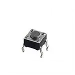


 工商网监
湘ICP备2023018690号
工商网监
湘ICP备2023018690号
