AN11231
KNX evaluation board using LPC1227 and NCN5120
Rev. 1 — 1 July 2012
Application note
Document information
Info
Content
Keywords
KNX, LPC1227, On Semiconductor NCN5120, Weinzierl Engineering
GmbH, Building Automation, Sensors, HVAC, Lighting, ARM Cortex M0,
Twisted pair TP1
Abstract
This application note describes the OM13042 KNX evaluation board that
uses the LPC1227 Cortex M0 microcontroller and the NCN5120 KNX
TP1 physical layer transceiver from On Semiconductor.
�AN11231
NXP Semiconductors
KNX evaluation board
Revision history
Rev
Date
Description
1
Initial version
20120701
Contact information
For more information, please visit: http://www.nxp.com
For sales office addresses, please send an email to: salesaddresses@nxp.com
AN11231
Application note
All information provided in this document is subject to legal disclaimers.
Rev. 1 — 1 July 2012
© NXP B.V. 2012. All rights reserved.
2 of 18
�AN11231
NXP Semiconductors
KNX evaluation board
1. Document purpose
The purpose of this document is to describe the OM13042 KNX evaluation board design.
This document is intended for technical persons such as system architects, hardware
and software engineers interested in designing and developing a KNX device using an
NXP microcontroller.
2. Introduction
The KNX evaluation board is an example implementation for KNX devices using an NXP
Cortex M0 microcontroller LPC1227, the KNX twisted pair transceiver NCN1520 from On
Semiconductor and a KNX System B software stack from Weinzierl Engineering GmbH.
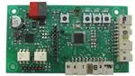
Fig 1.
OM 13042 KNX TP1 NCN5120 LPC1227 evaluation board
The board supports the connection of actuators, sensors, switches or other applications
in a building automation network. The evaluation board is available under the full name
OM13042,598 and order code 935298293598.
3. Hardware
This chapter provides an overview of the board, its partitioning and all other hardware
related information of the evaluation board.
3.1 Overview
An overview of the main components of the evaluation board is given in Fig 2. The
transceiver IC NCN5120 connects via UART to the LPC1227 microcontroller.
Furthermore the transceiver creates a regulated 3.3 V power supply for the
microcontroller from the unregulated bus supply. The LPC1227 creates a clock signal for
AN11231
Application note
All information provided in this document is subject to legal disclaimers.
Rev. 1 — 1 July 2012
© NXP B.V. 2012. All rights reserved.
3 of 18
�AN11231
NXP Semiconductors
KNX evaluation board
the digital control part of the transceiver. Several buttons and LEDs are available as
sensor and actuator inputs to the system.
Buttons LEDs
+ 3.3 V
CLK
KNX TP1
NCN5120
UART
LPC1227
Mode
UART
isolation
debug
UART
Extension header
Fig 2.
Evaluation board overview
3.2 PCB overview
The evaluation board is a two layer board with all components on the top side of the
board. The component placement is given in Fig 5.
Fig 3.
Component placement top side
The upper left part of the board contains the KNX TP1 header K1 to connect the KNX
bus. Below the KNX connector, the board contains the physical transceiver part of the
design. On the left bottom side the isolated UART interface is available on header SV2.
AN11231
Application note
All information provided in this document is subject to legal disclaimers.
Rev. 1 — 1 July 2012
© NXP B.V. 2012. All rights reserved.
4 of 18
�AN11231
NXP Semiconductors
KNX evaluation board
User interface
KNX Physical Layer
Fig 4.
SWD
Measure
Isolated UART
Microcontroller
Expansion connector
Partitioning of the design
In the middle of the board, a header is available to measure the various signals between
the microcontroller and the transceiver. The top part contains the user interaction: LEDs
and buttons. The header on the right hand side provides a debug probe connection that
complies with the Serial Wire Debug (SWD) interface standard. To interface with other
boards an extension connector is present on the lower part of the board. See Fig 4.
3.3 Microcontroller
To allow easy KNX application development, the development board is equipped with an
LPC1227 Cortex M0 microcontroller with a flash memory size of 128 kB and 8 kB of
RAM. This allows for downgrading to other LPC122x microcontrollers with smaller
memory sizes while maintaining software and hardware compatibility. More information
on the LPC122x microcontroller series is available in the LPC122x datasheet [1].
The microcontroller uses UART1 to connect to the transceiver. Furthermore, some
GPIO’s are used to connect to the KNX Phy. The second UART (UART0) on the design
can be used to connect an external terminal program for debugging messages. The
debug UART is electrically isolated from the design and the KNX bus.
Software can be downloaded via the SWD interface and debugged to the microcontroller
on header J4. The LPC1227 user manual [2] contains a full description of the processing
core and all the on board peripherals of the microcontroller. Fig 5 gives the schematic of
the microcontroller section of the board.
AN11231
Application note
All information provided in this document is subject to legal disclaimers.
Rev. 1 — 1 July 2012
© NXP B.V. 2012. All rights reserved.
5 of 18
�AN11231
NXP Semiconductors
KNX evaluation board
Fig 5.
LPC1227 Microcontroller section of the schematic
AN11231
Application note
All information provided in this document is subject to legal disclaimers.
Rev. 1 — 1 July 2012
© NXP B.V. 2012. All rights reserved.
6 of 18
�AN11231
NXP Semiconductors
KNX evaluation board
3.4 KNX physical layer
The twisted pair 1 (TP1) KNX physical layer standard is used in the design. The design
uses an NCN5120 receiver-transmitter IC for TP1 communication. The NCN5120
handles the transmission and reception of data on the bus. It generates stabilized
voltages from the unregulated KNX bus for its own power needs as well as power for
external devices as the microcontroller in this design. The NCN5120 assures safe
coupling to and decoupling from the bus. Bus monitoring warns the external
microcontroller for loss of power so that critical data can be stored in time.
AN11231
Application note
All information provided in this document is subject to legal disclaimers.
Rev. 1 — 1 July 2012
© NXP B.V. 2012. All rights reserved.
7 of 18
�AN11231
NXP Semiconductors
KNX evaluation board
Fig 6.
KNX physical layer using OnSemi NCN5120
AN11231
Application note
All information provided in this document is subject to legal disclaimers.
Rev. 1 — 1 July 2012
© NXP B.V. 2012. All rights reserved.
8 of 18
�AN11231
NXP Semiconductors
KNX evaluation board
3.5 Isolated UART interface
The isolated debug UART can be used for showing messages on a terminal. The 6-pin
connector is compatible with a TTL-232R-3V3 cable from FTDI (Farnell order code:
1329311). This cable is shown in Fig 7.
Fig 7.
FTDI TTL-232R-3V3 cable
Fig 8 gives the schematic diagram of the electrical isolate debug UART. This connection
can both be used for input and output to the design and is not necessary for an end
product.
Fig 8.
Isolated debug UART Interface
3.6 Expansion connector
To facilitate the connection of external hardware the expansion connector SV1 is
available. The expansion connector can be used to connect external hardware boards for
lighting, sensor, HVAC or other control purposes.
The connections of the expansion connector are given in Fig 9. All the connections,
except ground and power, are directly connected to the microcontroller. The connections
available support the usage of the 16-bit timers CTB16B0 and CTB16B1, and the 32-bit
timers CT32B0 and CT32B1 for PWM generation. Furthermore, two analog to digital
inputs are available; for communication purposes an SPI/SSP or I2C connection is
available.
AN11231
Application note
All information provided in this document is subject to legal disclaimers.
Rev. 1 — 1 July 2012
© NXP B.V. 2012. All rights reserved.
9 of 18
�AN11231
NXP Semiconductors
KNX evaluation board
Not all these I/O connections are available simultaneously as the microcontroller uses pin
multiplexing to select the specific function of an I/O pin. For detailed information on the
pin multiplexing possibilities of the LPC1227 microcontroller see the LPC1227 user
manual [2].
Fig 9.
Expansion connector
AN11231
Application note
All information provided in this document is subject to legal disclaimers.
Rev. 1 — 1 July 2012
© NXP B.V. 2012. All rights reserved.
10 of 18
�AN11231
NXP Semiconductors
KNX evaluation board
4. Bill of Materials
Table 1.
Part
Component list
Value
Device
Package
Description
C1
22pF
C0805K
CAPACITOR, European symbol
C2
22pF
C-EUC0805K
C0805K
CAPACITOR, European symbol
C4
100nF
C-EUC0805K
C0805K
CAPACITOR, European symbol
C5
100nF
C-EUC0805K
C0805K
CAPACITOR, European symbol
C8
470nF/50V
C-EUC0805K
C0805K
CAPACITOR, European symbol
C9
10uF/10V/X7R
C-EUC0805K
C0805K
CAPACITOR, European symbol
C11
100nF
C-EUC0805K
C0805K
CAPACITOR, European symbol
C12
22pF
C-EUC0805K
C0805K
CAPACITOR, European symbol
C13
22pF
C-EUC0805K
C0805K
CAPACITOR, European symbol
C14
4u7
C-EUC0805K
C0805K
CAPACITOR, European symbol
C15
100nF
C-EUC0805K
C0805K
CAPACITOR, European symbol
C16
100nF
C-EUC0805K
C0805K
CAPACITOR, European symbol
C24
4n7
C-EUC0805K
C0805K
CAPACITOR, European symbol
C25
100uF/35V
CPOL-EUF
PANASONIC_F
POLARIZED CAPACITOR, European
symbol
C26
100nF
C-EUC0805K
C0805K
CAPACITOR, European symbol
D1
BYG21
DIODEDO214AC
DO214AC
DIODE
1021748
D2
SMBJ43CA
SUPPRESSORSMBJ
SMBJ
Suppressor diode
1827691
J4
MC9A22-2034
MC9A22-2034
HEADER, RIGHT ANGLE, 20 WAY
1099248
JP10
C-EUC0805K
PINHD-2X2
2X02
Farnell
1712595
PIN HEADER
TP1 pins and connector
2x
1336225 +
4016014
NPI54C221KTRF 5.8x5.2
NIC Components, SMD non-shielded
RS online
740-9619
RED0805
LEDCHIPLED_08
05
CHIPLED_0805
LED (Check Anode/Cathode
placement!)
1716768
LED2
GREEN0805
LEDCHIPLED_08
05
CHIPLED_0805
LED
1716766
LED3
GREEN0805
LEDCHIPLED_08
05
CHIPLED_0805
LED
1716766
OK1
H11L2MS
H11L2MS
DIL6-SMD
6-Pin DIP Optocoupler
1086683
OK2
H11L2MS
H11L2MS
DIL6-SMD
6-Pin DIP Optocoupler
1086683
Q1
16MHz
CRYSTAL4
XTAL4
1712816
Q2
32.768kHz
RTCCRYSTAL
XTAL2
1278036
R1
27E/1W/2512
R-EU_R2512
R2512
RESISTOR, European symbol, +/- 5%
R2
1k0
R-EU_R0805
R0805
RESISTOR, European symbol
R3
1k0
R-EU_R0805
R0805
RESISTOR, European symbol
R4
nc
R-EU_R0805
R0805
RESISTOR, European symbol
K1
KNX
KNX
L5
220uH
LED1
AN11231
Application note
KNX
All information provided in this document is subject to legal disclaimers.
Rev. 1 — 1 July 2012
1265189
© NXP B.V. 2012. All rights reserved.
11 of 18
�AN11231
NXP Semiconductors
KNX evaluation board
Part
Value
Device
Package
Description
R5
470E
R-EU_R0805
R0805
RESISTOR, European symbol
R6
1k0
R-EU_R0805
R0805
RESISTOR, European symbol
R7
1k0
R-EU_R0805
R0805
RESISTOR, European symbol
R8
nc
R-EU_R0805
R0805
RESISTOR, European symbol
R14
47E
R-EU_R0805
R0805
RESISTOR, European symbol
R17
10k
R-EU_R0805
R0805
RESISTOR, European symbol
R18
10k
R-EU_R0805
R0805
RESISTOR, European symbol
R19
470E
R-EU_R0805
R0805
RESISTOR, European symbol
R20
470E
R-EU_R0805
R0805
RESISTOR, European symbol
R26
1E
R-EU_R0805
R0805
RESISTOR, European symbol
R27
10k
R-EU_R0805
R0805
RESISTOR, European symbol
B3FS-1000
SWITCHTACT_DTSM-6
OMRON ELECTRONIC
COMPONENTS - B3FS-1000 SWITCH, FLAT, SPNO
3121161
B3FS-1000
SWITCHTACT_DTSM-6
OMRON ELECTRONIC
COMPONENTS - B3FS-1000 SWITCH, FLAT, SPNO
3121161
B3FS-1000
SWITCHTACT_DTSM-6
OMRON ELECTRONIC
COMPONENTS - B3FS-1000 SWITCH, FLAT, SPNO
3121161
SWITCHTACT_DTSM-6
OMRON ELECTRONIC
COMPONENTS - B3FS-1000 SWITCH, FLAT, SPNO
3121161
HEADER, RIGHT ANGLE, 20 WAY
1099248
S1
S2
S3
B3FS-1000
B3FS-1000
B3FS-1000
S4
B3FS-1000
B3FS-1000
SV1
MC9A22-2034
MC9A22-2034
SV2
MA06-1
MA06-1
PIN HEADER
SV3
MA10-1
MA10-1
PIN HEADER
TP1
PINHD-1X1
1X01
PIN HEADER
TP2
PINHD-1X1
1X01
PIN HEADER
U1
NCN5120
NCN5120
QFN40_6X6_NCN On Semiconductor KNX TP1
5120
transceiver
U3
LPC1227FBD48
LPC122XFBD48
SOT313-2
AN11231
Application note
NXP ARM Cortex M0 32 bit
Microcontroller
All information provided in this document is subject to legal disclaimers.
Rev. 1 — 1 July 2012
Farnell
1862476
© NXP B.V. 2012. All rights reserved.
12 of 18
�AN11231
NXP Semiconductors
KNX evaluation board
5. Device configuration
The demo board is programmed with the App_DemoBoardNXP_LPC12xx.hex file to
create an example KNX device. Together with an example project for the ETS tool (the
manufacturer independent configuration tool from KNX Association), the user can setup
a small KNX network using the OM13042 board.
The example application file for the microcontroller contains a limited version of the KNX
stack from Weinzierl Engineering. For more information on the KNX system stack refer to
Weinzierl Engineering [4].
AN11231
Application note
Table 2.
Accompanying files AN11231
File name
Description
App_DemoBoardNXP_LPC12xx.hex
Flash file for the LPC1227 microcontroller
Test_Project_App_Demo_NXP_2012_04_11.pr5
Example project for KNX ETS configuration
tool
All information provided in this document is subject to legal disclaimers.
Rev. 1 — 1 July 2012
© NXP B.V. 2012. All rights reserved.
13 of 18
�AN11231
NXP Semiconductors
KNX evaluation board
6. References
AN11231
Application note
[1]
Product data sheet LPC122x 32-bit ARM Cortex-M0 microcontroller, Rev. 2 — 26
August 2011 http://www.nxp.com/documents/data_sheet/LPC122X.pdf
[2]
UM10441, LPC1224/25/26/27 User manual, Rev. 2 — 19 September 2011,
http://www.nxp.com/documents/user_manual/UM10441.pdf
[3]
NCN5120 datasheet, Rev.1 – May 2011 On Semiconductors
[4]
Weinzierl Engineering GmbH, http://www.weinzierl.de/
All information provided in this document is subject to legal disclaimers.
Rev. 1 — 1 July 2012
© NXP B.V. 2012. All rights reserved.
14 of 18
�AN11231
NXP Semiconductors
KNX evaluation board
7. Legal information
7.1 Definitions
Draft — The document is a draft version only. The content is still under
internal review and subject to formal approval, which may result in
modifications or additions. NXP Semiconductors does not give any
representations or warranties as to the accuracy or completeness of
information included herein and shall have no liability for the consequences
of use of such information.
7.2 Disclaimers
Limited warranty and liability — Information in this document is believed to
be accurate and reliable. However, NXP Semiconductors does not give any
representations or warranties, expressed or implied, as to the accuracy or
completeness of such information and shall have no liability for the
consequences of use of such information. NXP Semiconductors takes no
responsibility for the content in this document if provided by an information
source outside of NXP Semiconductors.
In no event shall NXP Semiconductors be liable for any indirect, incidental,
punitive, special or consequential damages (including - without limitation lost profits, lost savings, business interruption, costs related to the removal
or replacement of any products or rework charges) whether or not such
damages are based on tort (including negligence), warranty, breach of
contract or any other legal theory.
Notwithstanding any damages that customer might incur for any reason
whatsoever, NXP Semiconductors’ aggregate and cumulative liability
towards customer for the products described herein shall be limited in
accordance with the Terms and conditions of commercial sale of NXP
Semiconductors.
Right to make changes — NXP Semiconductors reserves the right to make
changes to information published in this document, including without
limitation specifications and product descriptions, at any time and without
notice. This document supersedes and replaces all information supplied prior
to the publication hereof.
Suitability for use — NXP Semiconductors products are not designed,
authorized or warranted to be suitable for use in life support, life-critical or
safety-critical systems or equipment, nor in applications where failure or
malfunction of an NXP Semiconductors product can reasonably be expected
to result in personal injury, death or severe property or environmental
damage. NXP Semiconductors and its suppliers accept no liability for
inclusion and/or use of NXP Semiconductors products in such equipment or
applications and therefore such inclusion and/or use is at the customer’s
own risk.
Applications — Applications that are described herein for any of these
products are for illustrative purposes only. NXP Semiconductors makes no
representation or warranty that such applications will be suitable for the
specified use without further testing or modification.
Semiconductors accepts no liability for any assistance with applications or
customer product design. It is customer’s sole responsibility to determine
whether the NXP Semiconductors product is suitable and fit for the
customer’s applications and products planned, as well as for the planned
application and use of customer’s third party customer(s). Customers should
provide appropriate design and operating safeguards to minimize the risks
associated with their applications and products.
NXP Semiconductors does not accept any liability related to any default,
damage, costs or problem which is based on any weakness or default in the
customer’s applications or products, or the application or use by customer’s
third party customer(s). Customer is responsible for doing all necessary
testing for the customer’s applications and products using NXP
Semiconductors products in order to avoid a default of the applications and
the products or of the application or use by customer’s third party
customer(s). NXP does not accept any liability in this respect.
Export control — This document as well as the item(s) described herein
may be subject to export control regulations. Export might require a prior
authorization from competent authorities.
Evaluation products — This product is provided on an “as is” and “with all
faults” basis for evaluation purposes only. NXP Semiconductors, its affiliates
and their suppliers expressly disclaim all warranties, whether express,
implied or statutory, including but not limited to the implied warranties of noninfringement, merchantability and fitness for a particular purpose. The entire
risk as to the quality, or arising out of the use or performance, of this product
remains with customer.
In no event shall NXP Semiconductors, its affiliates or their suppliers be
liable to customer for any special, indirect, consequential, punitive or
incidental damages (including without limitation damages for loss of
business, business interruption, loss of use, loss of data or information, and
the like) arising out the use of or inability to use the product, whether or not
based on tort (including negligence), strict liability, breach of contract, breach
of warranty or any other theory, even if advised of the possibility of such
damages.
Notwithstanding any damages that customer might incur for any reason
whatsoever (including without limitation, all damages referenced above and
all direct or general damages), the entire liability of NXP Semiconductors, its
affiliates and their suppliers and customer’s exclusive remedy for all of the
foregoing shall be limited to actual damages incurred by customer based on
reasonable reliance up to the greater of the amount actually paid by
customer for the product or five dollars (US$5.00). The foregoing limitations,
exclusions and disclaimers shall apply to the maximum extent permitted by
applicable law, even if any remedy fails of its essential purpose.
7.3 Trademarks
Notice: All referenced brands, product names, service names and
trademarks are property of their respective owners.
Customers are responsible for the design and operation of their applications
and products using NXP Semiconductors products, and NXP
AN11231
Application note
All information provided in this document is subject to legal disclaimers.
Rev. 1 — 1 July 2012
© NXP B.V. 2012. All rights reserved.
15 of 18
�AN11231
NXP Semiconductors
KNX evaluation board
8. List of figures
Fig 1.
Fig 2.
Fig 3.
Fig 4.
Fig 5.
Fig 6.
Fig 7.
Fig 8.
Fig 9.
OM 13042 KNX TP1 NCN5120 LPC1227
evaluation board ............................................... 3
Evaluation board overview ................................ 4
Component placement top side ........................ 4
Partitioning of the design .................................. 5
LPC1227 Microcontroller section of the
schematic .......................................................... 6
KNX physical layer using OnSemi NCN5120 .... 8
FTDI TTL-232R-3V3 cable ................................ 9
Isolated debug UART Interface ......................... 9
Expansion connector ...................................... 10
AN11231
Application note
All information provided in this document is subject to legal disclaimers.
Rev. 1 — 1 July 2012
© NXP B.V. 2012. All rights reserved.
16 of 18
�AN11231
NXP Semiconductors
KNX evaluation board
9. List of tables
Table 1.
Table 2.
Component list ................................................ 11
Accompanying files AN11231 ......................... 13
AN11231
Application note
All information provided in this document is subject to legal disclaimers.
Rev. 1 — 1 July 2012
© NXP B.V. 2012. All rights reserved.
17 of 18
�AN11231
NXP Semiconductors
KNX evaluation board
10. Contents
1.
2.
3.
3.1
3.2
3.3
3.4
3.5
3.6
4.
5.
6.
7.
7.1
7.2
7.3
8.
9.
10.
Document purpose .............................................. 3
Introduction ......................................................... 3
Hardware .............................................................. 3
Overview ............................................................ 3
PCB overview..................................................... 4
Microcontroller.................................................... 5
KNX physical layer ............................................. 7
Isolated UART interface ..................................... 9
Expansion connector .......................................... 9
Bill of Materials .................................................. 11
Device configuration ......................................... 13
References ......................................................... 14
Legal information .............................................. 15
Definitions ........................................................ 15
Disclaimers....................................................... 15
Trademarks ...................................................... 15
List of figures..................................................... 16
List of tables ...................................................... 17
Contents ............................................................. 18
Please be aware that important notices concerning this document and the product(s)
described herein, have been included in the section 'Legal information'.
© NXP B.V. 2012.
All rights reserved.
For more information, visit: http://www.nxp.com
For sales office addresses, please send an email to: salesaddresses@nxp.com
Date of release: 1 July 2012
Document identifier: AN11231
�