NCT375
Industry Standard Digital
Temperature Sensor with
2‐wire Interface
The NCT375 is a two-wire serially programmable temperature
sensor with an over-temperature/interrupt output pin to signal out of
limit conditions. This is an open-drain pin and can operate in either
comparator or interrupt mode. Temperature measurements are
converted into digital form using a high resolution (12 bit),
sigma-delta, analog-to-digital converter (ADC). The device operates
over the –55°C to +125°C temperature range.
Communication with the NCT375 is accomplished via the
SMBus/I2C interface. Three address selection pins, A2, A1 and A0,
can be used to connect up to 8 NCT375s to a single bus. Through this
interface the NCT375s internal registers may be accessed. These
registers allow the user to read the current temperature, change the
configuration settings and adjust the temperature limits.
The NCT375 has a wide supply voltage range of 3.0 V to 5.5 V. The
average supply current is 575 mA at 3.3 V. It also offers a shutdown
mode to conserve power. The typical shutdown current is 3 mA.
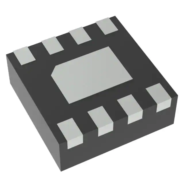
The NCT375 is available in three, space saving packages – 8-lead
DFN, 8-lead Micro8t and 8-lead SOIC and is also fully pin and
register compatible with the NCT75, LM75 and TCN75.
www.onsemi.com
DFN8
CASE 506AA
SOIC8
CASE 751
PIN ASSIGNMENT
SDA 1
8 VDD
SCL 2
(Top View)
OS/ALERT 3
6 A1
MARKING DIAGRAMS
8
12-bit Temperature-to-Digital Converter
Input Voltage Range from 3.0 V to 5.5 V
Temperature Range from −55°C to +125°C
SMBus/I2C Interface
Overtemperature Indicator
Support for SMBus/ALERT
Shutdown Mode for Low Power Consumption
One-shot Mode
Available in 8-pin DFN, 8-pin Micro8t and SOIC Packages
These Devices are Pb-Free, Halogen Free/BFR Free and are RoHS
Compliant
1
T375
AYWG
G
35MG
G
1
DFN8
Micro8t
M
= Date Code
A
= Assembly Location
Y
= Year
W
= Work Week
G
= Pb-Free Package
(Note: Microdot may be in either location)
8
Applications
•
•
•
•
•
•
•
•
7 A0
5 A2
GND 4
Features
•
•
•
•
•
•
•
•
•
•
Micro8t
CASE 846A
Computer Thermal Monitoring
Thermal Protection
Isolated Sensors
Battery Management
Office Electronics
Electronic Test Equipment
Thermostat Controls
System Thermal Management
1
NCT375
ALYW
G
SOIC8
A
L
Y
W
G
= Assembly Location
= Wafer Lot
= Year
= Work Week
= Pb-Free Package
ORDERING INFORMATION
See detailed ordering and shipping information in the package
dimensions section on page 13 of this data sheet.
© Semiconductor Components Industries, LLC, 2015
June, 2015 − Rev. 0
1
Publication Order Number:
NCT375/D
�NCT375
VDD
8
SDA
SCL
A2
A1
A0
1
2
5
REGISTERS
TWO-WIRE
INTERFACE
6
7
CONFIGURATION
THYST
TEMPERATURE
TOS
3
ONE-SHOT
OS/ALERT
CONTROL
LOGIC
DELTA-SIGMA
ADC
GND
4
Figure 1. Simplified Block Diagram
VDD 3.0 V To 5.5 V
CBYPASS
A2
ADDRESS
(SET AS DESIRED)
A1
A0
5
6
1
7
NCT375
OS/ALERT
2
SDA
SCL
SERIAL INTERFACE
3
NOTE: SDA, SCL AND OS/ALERT PINS
REQUIRE PULL-UP RESISTORS TO VDD
4
GND
Figure 2. Typical Application Circuit
Table 1. PIN FUNCTION DESCRIPTION
Pin No.
Pin Name
1
SDA
SMBus/I2C Serial Bi-directional Data Input/Output. Open-drain pin; needs a pull-up resistor.
Description
2
SCL
Serial Clock Input. Open-drain pin; needs a pull-up resistor.
3
OS/ALERT
4
GND
5
A2
SMBus/I2C Serial Bus Address Selection Pin. Connect to GND or VDD to set the desired I2C address.
6
A1
SMBus/I2C Serial Bus Address Selection Pin. Connect to GND or VDD to set the desired I2C address.
7
A0
SMBus/I2C Serial Bus Address Selection Pin. Connect to GND or VDD to set the desired I2C address.
8
VDD
Over-temperature Indicator. Open-drain output; needs a pullup resistor. Active Low output.
Power Supply Ground.
Positive Supply Voltage, 3.0 V to 5.5 V. Bypass to ground with a 0.1 mF bypass capacitor.
www.onsemi.com
2
�NCT375
Table 2. ABSOLUTE MAXIMUM RATINGS
Rating
Symbol
Supply Voltage
VDD
Input Voltage on SCL, SDA, A2, A1, A0 and OS/ALERT.
Input Current on SDA, A2, A1, A0 and OS/ALERT.
Value
Unit
−0.3 to +7
V
−0.3 to VDD + 0.3
V
IIN
−1 to +50
mA
TJ(max)
150.7
°C
Operating Temperature Range
TOP
−55 to 125
°C
Storage Temperature Range
TSTG
−65 to 160
°C
ESD Capability, Human Body Model (Note 1)
ESDHBM
2,000
V
ESD Capability, Machine Model (Note 1)
ESDMM
400
V
Maximum Junction Temperature
Stresses exceeding those listed in the Maximum Ratings table may damage the device. If any of these limits are exceeded, device functionality
should not be assumed, damage may occur and reliability may be affected.
1. This device series incorporates ESD protection and is tested by the following methods:
ESD Human Body Model tested per AEC−Q100−002 (EIA/JESD22−A114)
ESD Machine Model tested per AEC−Q100−003 (EIA/JESD22−A115)
Table 3. OPERATING RANGES
Rating
Symbol
Min
Max
Unit
Operating Supply Voltage
VIN
3.0
5.5
V
Operating Ambient Temperature Range
TA
−55
125
°C
Table 4. SMBus TIMING SPECIFICATIONS
Parameter
Symbol
Min
Typ
Max
Unit
fSCL
DC
−
400
kHz
Start Condition Hold Time
tHD:STA
0.6
−
−
ms
Stop Condition Setup Time
tSU:STO
100
−
−
ns
1.3
−
−
ms
Serial Clock Frequency
Clock Low Period
Test Conditions
90% of SCL to 10% of SDA
tLOW
Clock High Period
0.6
−
−
ms
tSU:STA
tHIGH
90% of SCL to 90% of SDA
100
−
−
ns
Data Setup Time
tSU:DAT
10% of SDA to 10% of SCL
100
−
−
ns
Data Hold Time (Note 2)
tHD:DAT
10% of SCL to 10% of SDA
0
−
76
ns
Start Condition Setup Time
SDA/SCL Rise Time
tR
−
300
−
ns
SDA/SCL Fall Time
tF
−
300
−
ns
tRESET
1.3
−
−
ms
tBUF
1.3
−
−
ms
tTIMEOUT
75
−
325
ms
Minimum RESET Pulse Width
Bus Free Time Between STOP & START Conditions
SDA Time Low for Reset of Serial Interface
Functional operation above the stresses listed in the Recommended Operating Ranges is not implied. Extended exposure to stresses beyond
the Recommended Operating Ranges limits may affect device reliability.
2. This refers to the hold time when the NCT375 is writing data to the bus.
tR
tF
tHD;STA
tLOW
SCL
tHD;STA
tHD;DAT
tHIGH
tSU;STA
tSU;DAT
tSU;STO
SDA
tBUF
STOP START
START
Figure 3. Serial Interface Timing
www.onsemi.com
3
STOP
�NCT375
Table 5. ELECTRICAL CHARACTERISTICS
(TA = TMIN to TMAX, VDD = 3.0 V to 5.5 V. All specifications for −55°C to +125°C, unless otherwise noted.)
Parameter
Test Conditions
Min
Typ
Max
Unit
−
−
−
−
−
−
±1
±2
±3
°C
TEMPERATURE SENSOR AND ADC
Accuracy at VDD = 3.0 V to 5.5 V
TA = 0°C to +70°C
TA = −25°C to +100°C
TA = −55°C to +125°C
ADC Resolution
−
12
−
Bits
Temperature Resolution
−
0.0625
−
°C
−
48.5
−
ms
−
80
−
ms
3.0
−
5.5
V
2.75
−
−
V
−
−
0.8
mA
Temperature Conversion Time
One-shot Mode
Update Rate
POWER REQUIREMENTS
Supply Voltage
POR Threshold
I2 C
Supply Current
Peak Current while Converting and
Interface Inactive
Average Current
Average Current over 1 Conversion Cycle
−
0.44
0.575
mA
Shutdown Mode at 3.3 V
Supply Current in Shutdown Mode
−
3
12
mA
IOL = 4 mA
−
0.15
0.4
V
OS/ALERT OUTPUT (OPEN DRAIN)
Output Low Voltage, VOL
Pin Capacitance
−
10
−
pF
OS/ALERT Pin Pulled Up to 5.5 V
−
0.1
5
mA
Input Current
VIN = 0 V to VDD
−
−
1
mA
Input Low Voltage, VIL
VDD = 3.3 V (Note 3)
−
−
0.3 x VDD
V
Input High Voltage, VIH
VDD = 3.3 V (Note 3)
0.7xVDD
−
−
V
SCL, SDA Glitch Rejection
Input Filtering Suppresses Noise Spikes of
Less than 50 ns
−
−
50
ns
−
3
−
pF
High Output Leakage Current, IOH
DIGITAL INPUTS (SDA, SCL)
Pin Capacitance
DIGITAL OUTPUT (SDA) (OPEN DRAIN)
Output High Current, IOH
VOH = 5 V
−
−
1
mA
Output Low Voltage, VOL
IOL = 3 mA
−
−
0.4
V
−
3
−
pF
Output Capacitance, COUT
Product parametric performance is indicated in the Electrical Characteristics for the listed test conditions, unless otherwise noted. Product
performance may not be indicated by the Electrical Characteristics if operated under different conditions.
3. Guaranteed by characterization, not production tested.
www.onsemi.com
4
�NCT375
APPLICATION INFORMATION
Functional Description
While the ADC of the NCT375 can theoretically measure
temperatures in the range of −128°C to 127°C, the NCT375
is guaranteed to measure from −55°C to +125°C.
Table 6 shows the relevant temperature bits for a 12 bit
temperature reading. A 2-byte read is required to obtain the
full 12 bit temperature reading. If an 8 bit (1°C resolution)
reading is required then a single byte read is sufficient.
The NCT375 temperature sensor converts an analog
temperature measurement to a digital representation by
using an on-chip measurement transistor and a 12 bit
Delta-Sigma ADC.
The device includes an open drain ALERT output which
can be used to signal that the programmed temperature limit
has been exceeded.
The two main modes of operation are normal and
shutdown mode. In normal mode the NCT375 performs
a new temperature conversion every 80 ms. This new value
is then updated to the temperature value register
(address 0x00) and also compared to the TOS register limit
(default = 80°C). If the temperature value register is read
during the conversion sequence the value returned is the
previously stored value. A bus read does not affect the
conversion that is in progress.
In shutdown mode temperature conversion is disabled and
the temperature value register holds the last valid
temperature reading. The NCT375 can still be
communicated with in this mode as the interface is still
active. The device mode is controlled via bit 0 of the
configuration register.
While in shutdown mode a conversion can be initiated by
writing an arbitrary value to the one-shot register (0x04).
This has the effect of powering up the NCT375, performing
a conversion, comparing the new temperature with the
programmed limit and then going back into shutdown mode.
The OS/ALERT pin can be configured in many ways to
allow it to be used in many different system configurations.
The overtemperature output can be configured to operate
as a comparator type output (which is self clearing once the
temperature has returned below the hysteresis value) or an
interrupt type output (which requires the master to read an
internal register AND the temperature to return below the
hysteresis value before going into an inactive state). The
ALERT pin can also be configured as an active high or active
low output.
Table 6. 12-BIT TEMPERATURE DATA FORMAT
Temperature
Binary Value
D15 to D4
Hex Value
−55°C
1100 1001 0000
0xC90
−25°C
1110 0111 0000
0xE70
−0.0625°C
1111 1111 1111
0xFFF
0°C
0000 0000 0000
0x000
+0.0625°C
0000 0000 0001
0x001
+25°C
0001 1001 0000
0x190
+75.25°C
0100 1011 0100
0x4B4
+100°C
0110 0100 0000
0x640
+125°C
0111 1101 0000
0x7D0
Temperature Data Conversion
12-bit Temperature Data Format
Positive Temperature = ADC Code (decimal)/16
Example 190h = 400d/16 = +25°C
Negative Temperature = (ADC Code(decimal) − 4096)/16
Example E70h = (3696d – 4096)/16 = −25°C
One-shot Mode
One of the features of the NCT375 is a One-shot
Temperature Measurement Mode. This mode is useful if
reduced power consumption is a design requirement.
To enable one-shot mode bit 5 of the configuration
register needs to be set. Once, enabled, the NCT375 goes
immediately into shutdown mode. Here, the current
consumption is reduced to a typical value of 3 mA. Writing
address 0x04 to the address pointer register initiates a
one-shot temperature measurement. This powers up the
NCT375, carries out a temperature measurement, and then
powers down again. The data written to this register is
irrelevant and is not stored. It is the write operation that
causes the one-shot conversion.
Temperature Measurement Results
The results of the on chip temperature measurements are
stored in the temperature value register and compared with
the TOS and THYST limit register.
The temperature value, TOS and THYST registers are
16 bits wide and have a resolution of 0.0625°C. The data is
stored as a 12 bit 2s complement word. The data is left
justified, D15 is the MSB and is the sign bit. The four LSBs
(D3 to D0) are always 0 as they are not part of the result.
www.onsemi.com
5
�NCT375
Registers
The NCT375 contains six registers for configuring and
reading the teperature: the address pointer register, 4 data
registers and a one-shot register. The configuration register,
the address pointer register and the one-shot register are all
8 bits wide while the temperature register, THYST and TOS
registers are all 16 bits wide. All registers, except for the
temperature register, can be be read from and written to (the
temperature register is read only). The power on state and
address of each register are listed in Table 9.
82°C
81°C
80°C
TOS
Temperature
79°C
78°C
77°C
76°C
75°C
THYST
74°C
Address Pointer Register
The address pointer register is used to select which
register is to respond to a read or write operation. The three
LSBs (P2, P1 & P0) of this write only register are used to
select the appropriate register. On power up this register is
loaded with a value of 0x00 and so points to the temperature
register. Table 7 shows the bits of the address pointer register
and Table 8 shows the pointer address selecting each of the
registers available.
73°C
72°C
OS/ALERT PIN
(COMPARATOR MODE)
POLARITY = 0
OS/ALERT PIN
(INTERRUPT MODE)
POLARITY = 0
Table 7. ADDRESS POINTER REGISTER
OS/ALERT PIN
(COMPARATOR MODE)
POLARITY = 1
Default
OS/ALERT PIN
(INTERRUPT MODE)
POLARITY = 1
P7
P6
P5
P4
P3
P2
P1
P0
0
0
0
0
0
0
0
0
Read
Read
Read
Table 8. REGISTER ADDRESSES SELECTION
Figure 4. One-shot OS/ALERT Pin Operation
Fault Queue
A fault is defined as when the temperature exceeds
a pre-defined temperature limit. This limit can be
programmed in the THYST and the TOS setpoint registers.
Bits 3 and 4 of the configuration register determine the
number of faults necessary to trigger the OS/ALERT pin. Up
to six faults can be programmed to prevent false tripping
when the NCT375 is used in a noisy temperature
environment. In order for the OS/ALERT output to be set
these faults must occur consecutively.
P2
P1
P0
Register Selected
0
0
0
Stored Temperature
0
0
1
Configuration
0
1
0
THYST Setpoint
0
1
1
TOS Setpoint
1
0
0
One-shot
Table 9. NCT375 REGISTER SET
Register Name
Hex
5C
0x00 (R)
Stored Temperature Value
0x0000
0
0x01 (R/W)
Configuration
0x00
−
0x02 (R/W)
THYST
0x4B00
75
0x03 (R/W)
TOS
0x5000
80
0x04 (R/W)
One-shot
0xXX
−
www.onsemi.com
6
Power-on
Default Value
Register
Address
�NCT375
Temperature Register
The temperature measured by the parts internal sensor is
stored in this 16-bit read only register. The data is stored in
twos complement format with the MSB as the sign bit. The
8 MSBs must be read frist followed by the 8 LSBs.
Table 10. TEMPERATURE VALUE REGISTER
MSB
LSB
D15
D14
D13
D12
D11
D10
D9
D8
D7
D6
D5
D4
D3
D2
D1
D0
0
0
0
0
0
0
0
0
0
0
0
0
X
X
X
X
Configuration Register
D[4:3]: Fault Queue
D4 D3 These two bits determine how many
overtemperature conditions occur before the OS/Alert
pin is triggered. This helps to prevent false triggering of
the output.
0 0 = 1 Fault (Default)
0 1 = 2 Faults
1 0 = 4 Faults
2 1 = 6 Faults
This 8-bit read/write register is used to configure the
NCT375 into its various modes of operation. The different
modes are listed in Table 11 and explained in more detail
below.
Table 11. CONFIGURATION REGISTER
Bit
Configuration
Default Value
D7
Reserved
0
D6
Reserved
0
D5
One-shot Mode
0
D4
Fault-queue
0
D3
Fault-queue
0
D2
OS/ALERT Pin Polarity
0
D1
Cmp/Int Mode
0
D0
Shutdown Mode
0
D2: OS/Alert pin polarity
This selects the polarity of the OS/Alert output pin.
D2 = 0 Output is active low. (Default)
D2 = 1 Output is active high.
D1: Cmp/Int
D1 = 0 Comparator mode. (Default)
D1 = 1 Interrupt mode.
D7: Reserved
Write 0 to this bit.
D0: Shutdown
D0 = 0 Normal mode – part is fully powered. (Default)
D0 = 1 Shutdown mode – all circuitry except for the
SMBus interface is powered down. Write a 0 to this bit to
power up again.
D6: Reserved
Write 0 to this bit.
D5: One-shot Mode
D5 = 0 Part is in normal mode and converting every
60 ms. (Default)
D5 = 1 Setting this bit puts the part into one-shot mode.
The part is normally powered down in this mode until the
one shot register is written to. Once this register is written
to one conversion is performed and the part returns to its
shutdown state.
THYST Register
The THYST register stores the temperature hysteresis
value for the overtemperature output. This value is picked to
stop the OS/Alert pin from being asserted and de-asserted in
noisy temperature environments. This limit is stored in the
16 bit register in twos complement format. The MSB is the
temperature sign bit. The 8 MSBs must be read first
followed by the 8 LSBs. The default value is +75°C.
Table 12. THYST REGISTER
MSB
LSB
D15
D14
D13
D12
D11
D10
D9
D8
D7
D6
D5
D4
D3
D2
D1
D0
0
1
0
0
1
0
1
1
0
0
0
0
X
X
X
X
TOS Register
This register stores the temperature limit at which the part
asserts an OS/Alert. Once the measured temperature reaches
this value an alert or overtemperature output is generated.
The data is stored in twos complement format with the MSB
as the sign bit. The 8 MSBs must be read frist followed by
the 8 LSBs. The default limit +80°C.
www.onsemi.com
7
�NCT375
Table 13. TOS REGISTER
MSB
LSB
D15
D14
D13
D12
D11
D10
D9
D8
D7
D6
D5
D4
D3
D2
D1
D0
0
1
0
1
0
0
0
0
0
0
0
0
X
X
X
X
www.onsemi.com
8
�NCT375
Serial Interface
Control of the NCT375 is carried out via the SMBus/I2C
compatible serial interface. The NCT375 is connected to this
bus as a slave device, under the control of a master device.
master writes to the slave device. If the R/W bit is
a one then the master reads from the slave device.
2. Data is sent over the serial bus in sequences of
nine clock pulses, eight bits of data followed by an
acknowledge bit from the receiver of data.
Transitions on the data line must occur during the
low period of the clock signal and remain stable
during the high period, since a low-to-high
transition when the clock is high can be interpreted
as a stop signal.
3. When all data bytes have been read or written,
stop conditions are established. In write mode, the
master pulls the data line high during the tenth
clock pulse to assert a stop condition. In read
mode, the master overrides the acknowledge bit by
pulling the data line high during the low period
before the ninth clock pulse. This is known as no
acknowledge. The master takes the data line low
during the low period before the tenth clock pulse,
then high during the tenth clock pulse to assert a
stop condition.
Serial Bus Address
Control of the NCT375 is carried out via the serial bus.
The NCT375 is connected to this bus as a slave device under
the control of a master device. The NCT375 has a 7-bit
serial address. The four MSBs are fixed and set to 1001
while the 3 LSBs can be configured by the user using pins
5, 6 and 7 (A2, A1 and A0). Each of these pins can be
configured in one of two ways low or high. This gives eight
different address options listed in Table 14 below. The state
of these pins is continually sampled and so can be changed
after power up.
Table 14. SERIAL BUS ADDRESS OPTIONS
MSBs
LSBs
Address
A6
A5
A4
A3
A2
A1
A0
Hex
1
0
0
1
0
0
0
0x48
1
0
0
1
0
0
1
0x49
1
0
0
1
0
1
0
0x4A
1
0
0
1
0
1
1
0x4B
1
0
0
1
1
0
0
0x4C
1
0
0
1
1
0
1
0x4D
1
0
0
1
1
1
0
0x4E
1
0
0
1
1
1
1
0x4F
Any number of bytes of data can be transferred over the
serial bus in one operation. However, it is not possible to mix
read and write in one operation because the type of operation
is determined at the beginning and cannot subsequently be
changed without starting a new operation.
Writing Data
There are two types of writes used in the NCT375:
The NCT375 also features a SMBus/I2C timeout function
whereby the SMBus/I2C interface times out after the
specified time when there is no activity on the SDA line. After
this time, the NCT375 resets the SDA line back to its idle state
(high impedance) and waits for the next start condition.
The serial bus protocol operates as follows:
1. The master initiates data transfer by establishing
a start condition, defined as a high to low
transition on the serial data line SDA, while the
serial clock line SCL remains high. This indicates
that an address/data stream is going to follow. All
slave peripherals connected to the serial bus
respond to the start condition and shift in the next
eight bits, consisting of a 7-bit address (MSB first)
plus a read/write (R/W) bit, which deternimes the
direction of the data transfer i.e. whether data is
written to, or read from, the slave device. The
peripheral with the address corresponding to the
transmitted address responds by pulling the data
line low during the low period before the ninth
clock pulse, known as the acknowledge bit. All
other devices on the bus now remain idle while the
selected device waits for data to be read from or
written to it. If the R/W bit is a zero then the
Setting up the Address Pointer Register for a Register
Read
To read data from a particular register, the address pointer
register must hold the address of the register being read. To
configure the address pointer register a single write
operation (shown in Figure 5). It consists of the device
address followed by the address being written to the address
pointer register. This will then be followed by a read
operation.
Writing Data to a Register
Due to the different size registers used by the NCT375,
there are two types of write operations. One is for the 8 bit
wide configuration register and the other for the 16 bit wide
limit registers.
Figure 6 shows the sequence required to write to the
configuration register. It consists of the device address, the
data register being written to and the data being written the
selected register.
The two temperature limit registers (THYST and TOS) are
16 bits wide and require two data bytes to be written to these
registers. This sequence is shown in Figure 7. It consists of
the device address, the data register being written to and the
two data byes being written to the selected register.
www.onsemi.com
9
�NCT375
1
9
1
9
SCL
SDA
A6
A5
START BY
MASTER
A4
A3
A2
A1
R/W
A0
D7
D6
ACK. BY
NCT375
FRAME 1
SERIAL BUS ADDRESS BYTE
D5
D4
D3
D2
D1
D0
ACK. BY
NCT375
FRAME 2
ADDRESS POINTER REGISTER BYTE
STOP BY
MASTER
Figure 5. Writing to the Address Pointer Register
1
9
1
9
SCL
SDA
A6
A5
START BY
MASTER
A4
A3
A2
A1
R/W
A0
D7
D6
ACK. BY
NCT375
FRAME 1
SERIAL BUS ADDRESS BYTE
D5
D4
D3
D2
D1
D0
FRAME 2
ADDRESS POINTER REGISTER BYTE
1
ACK. BY
NCT375
9
SCL (CONTINUED)
D7
SDA (CONTINUED)
D6
D5
D4
D3
D2
D1
D0
ACK. BY STOP BY
NCT375 MASTER
FRAME 3
DATA BYTE
Figure 6. Writing a Register Address to the Address Pointer Register, then
Writing a Single Byte of Data to the Configuration Register
1
9
1
9
SCL
SDA
A6
START BY
MASTER
A5
A4
A3
A2
A1
A0
FRAME 1
SERIAL BUS ADDRESS BYTE
R/W
D7
SDA
(CONTINUED)
D9
D4
D3
D1
D0
9
D7
D8
D6
D5
D4
ACK. BY
NCT375
FRAME 3
DATA BYTE
D2
1
9
D15 D14 D13 D12 D11 D10
D5
ACK. BY
NCT375
FRAME 2
ADDRESS POINTER REGISTER BYTE
1
SCL
(CONTINUED)
D6
ACK. BY
NCT375
D3
D2
D1
D0
ACK. BY
NCT375
FRAME 4
DATA BYTE
STOP BY
MASTER
Figure 7. Writing to the Address Pointer Register Followed by
Two Bytes of Data to a 16 Bit Limit Register
1
9
1
9
SCL
SDA
START BY
MASTER
A6
A5
A4
A3
A2
A1
A0 R/W
ACK. BY
NCT375
D7
D6
FRAME 1
SERIAL BUS ADDRESS BYTE
D5
D4
D3
10
D1
D0
NO ACK. BY
MASTER
FRAME 2
DATA BYTE FROM REGISTER
Figure 8. Reading Data from the Configuration Register
www.onsemi.com
D2
STOP BY
MASTER
�NCT375
1
9
1
9
SCL
SDA
A6
A5
START BY
MASTER
A4
A3
A2
A1
A0 R/W
D15 D14
ACK. BY
NCT375
FRAME 1
SERIAL BUS ADDRESS BYTE
D13
D12
D11 D10
D9
D8
ACK. BY
MASTER
FRAME 2
MSB DATA FROM TEMPERATURE
VALUE REGISTER
1
9
SCL (CONTINUED)
D7
SDA (CONTINUED)
D6
D5
D4
D3
D2
D1
D0
NO ACK. BY STOP BY
MASTER
MASTER
FRAME 3
LSB DATA FROM TEMPERATURE
VALUE REGISTER
Figure 9. Reading Data from the Temperature Value Register with Preset Pointer Register
1
9
1
9
SCL
SDA
A6
A5
A4
A3
A2
A1
A0
D7
R/W
D6
D5
D4
D3
D2
D1
D0
ACK. BY
NCT375
START BY
MASTER
ACK. BY
NCT375
FRAME 2
ADDRESS POINTER REGISTER BYTE
FRAME 1
SERIAL BUS ADDRESS BYTE
1
9
1
9
SCL
SDA
A6
A5
A4
A3
A2
A1
A0
R/W
D15 D14
D13
D12
D11
D10
D9
D8
ACK. BY
MASTER
ACK. BY
NCT375
REPEATED START BY
MASTER
FRAME 2
MSB DATA FROM TEMPERATURE
VALUE REGISTER
FRAME 1
SERIAL BUS ADDRESS BYTE
9
1
SCL (CONTINUED)
SDA (CONTINUED)
D7
D6
D5
D4
D3
D2
D1
D0
NO ACK. BY STOP BY
MASTER
MASTER
FRAME 3
LSB DATA FROM TEMPERATURE
VALUE REGISTER
Figure 10. Typical Pointer Set followed by Two Bytes Register Read
www.onsemi.com
11
�NCT375
Reading Data
Reading data from the NCT375 is done in two different
ways depending on the register being read. The
configuration register is only 8 bits wide so a single byte
read is used for this (shown in Figure 8). This consists of the
device address followed by the data from the register.
Reading the data in the temperature value register requires
a two byte read (shown in Figure 9). This consists of the
device address, followed by two bytes of data from the
temperature register (the first byte is the MSB). In both cases
the address pointer register of the register being read must
be written to prior to performing a read operation.
More information on comparator and interrupt modes
alsong with the SMBus alert mode are explained below.
Comparator Mode
In Comparator Mode, the OS/ALERT pin becomes active
when the measured temperature equals or exceeds the limit
stored in the TOS setpoint register. The pin returns to its
inactive status when the temperature drops below the THYST
setpoint register value.
NOTE: Shutdown mode does not reset the output state for
comparator mode.
Interrupt Mode
OS/ALERT Output Overtemperature Modes
The OS/ALERT output pin can operate in two different
modes – overtemperature mode and SMBus alert mode. The
pin defaults to overtemperature mode on power up. This
means that it becomes active when the measured
temperature meets or exceeds the limit stored in the TOS
setpoint register. At this point it can deal with the event in
one of two ways which depends on the mode it is in. The two
overtemperature modes are: comparator mode and interrupt
mode. Comparator mode is the default mode on power up.
In the interrupt mode, the OS/ALERT pin becomes active
when the temperature equals or exceeds the TOS limit for
a consecutive number of faults. It can be reset by performing
a read operation on any register in the NCT375. The output
can only become active again when the TOS limit has been
equalled or exceeded.
Figure 11 shows how both the interrupt and comparator
modes operate in relation to the output pin (OS/ALERT). It
also shows the operation of the polarity bit in the
configuration register.
www.onsemi.com
12
�NCT375
82°C
81°C
TOS
80°C
Temperature
79°C
78°C
77°C
76°C
75°C
THYST
74°C
73°C
72°C
OS/ALERT PIN
(COMPARATOR MODE)
POLARITY = 0
OS/ALERT PIN
(INTERRUPT MODE)
POLARITY = 0
OS/ALERT PIN
(COMPARATOR MODE)
POLARITY = 1
Read
Read
Read
OS/ALERT PIN
(INTERRUPT MODE)
POLARITY = 1
Figure 11. OS/ALERT Output Temperature Response Diagram
Table 15. ORDERING INFORMATION
Temperature Range
Temperature Accuracy
Package Description
Package Option†
NCT375DMR2G
−55°C to +125°C
±1°C
Micro8
(Pb−Free)
3,000 / Tape & Reel
NCT375DR2G
−55°C to +125°C
±1°C
SOIC−8
(Pb−Free)
2,500 / Tape & Reel
NCT375MNR2G
−55°C to +125°C
±1°C
DFN8
(Pb−Free)
3,000 / Tape & Reel
Model Number
†For information on tape and reel specifications, including part orientation and tape sizes, please refer to our Tape and Reel Packaging
Specifications Brochure, BRD8011/D.
Micro8 is a trademark of International Rectifier.
www.onsemi.com
13
�MECHANICAL CASE OUTLINE
PACKAGE DIMENSIONS
DFN8 2x2, 0.5P
CASE 506AA
ISSUE F
DATE 04 MAY 2016
1
SCALE 4:1
D
PIN ONE
REFERENCE
2X
0.10 C
2X
0.10 C
A
B
L1
ÇÇ
ÇÇ
ÇÇ
DETAIL A
E
OPTIONAL
CONSTRUCTIONS
ÉÉ
ÇÇ
ÉÉ
ÇÇ
EXPOSED Cu
TOP VIEW
A
DETAIL B
0.10 C
NOTES:
1. DIMENSIONING AND TOLERANCING PER
ASME Y14.5M, 1994 .
2. CONTROLLING DIMENSION: MILLIMETERS.
3. DIMENSION b APPLIES TO PLATED
TERMINAL AND IS MEASURED BETWEEN
0.15 AND 0.20 MM FROM TERMINAL TIP.
4. COPLANARITY APPLIES TO THE EXPOSED
PAD AS WELL AS THE TERMINALS.
L
L
DIM
A
A1
A3
b
D
D2
E
E2
e
K
L
L1
ÉÉ
ÉÉ
ÇÇ
A3
MOLD CMPD
A1
DETAIL B
0.08 C
(A3)
NOTE 4
SIDE VIEW
DETAIL A
ALTERNATE
CONSTRUCTIONS
A1
C
D2
8X
4
1
SEATING
PLANE
RECOMMENDED
SOLDERING FOOTPRINT*
L
5
8
e/2
e
8X
0.90
b
0.05 C
8X
0.50
2.30
1
0.10 C A B
8X
0.30
NOTE 3
BOTTOM VIEW
0.50
PITCH
DIMENSIONS: MILLIMETERS
*For additional information on our Pb−Free strategy and soldering
details, please download the ON Semiconductor Soldering and
Mounting Techniques Reference Manual, SOLDERRM/D.
GENERIC
MARKING DIAGRAM*
1
1.30
PACKAGE
OUTLINE
E2
K
MILLIMETERS
MIN
MAX
0.80
1.00
0.00
0.05
0.20 REF
0.20
0.30
2.00 BSC
1.10
1.30
2.00 BSC
0.70
0.90
0.50 BSC
0.30 REF
0.25
0.35
−−−
0.10
XXMG
G
XX = Specific Device Code
M = Date Code
G
= Pb−Free Device
*This information is generic. Please refer to
device data sheet for actual part marking.
Pb−Free indicator, “G” or microdot “G”, may
or may not be present. Some products may
not follow the Generic Marking.
DOCUMENT NUMBER:
DESCRIPTION:
98AON18658D
Electronic versions are uncontrolled except when accessed directly from the Document Repository.
Printed versions are uncontrolled except when stamped “CONTROLLED COPY” in red.
DFN8, 2.0X2.0, 0.5MM PITCH
PAGE 1 OF 1
onsemi and
are trademarks of Semiconductor Components Industries, LLC dba onsemi or its subsidiaries in the United States and/or other countries. onsemi reserves
the right to make changes without further notice to any products herein. onsemi makes no warranty, representation or guarantee regarding the suitability of its products for any particular
purpose, nor does onsemi assume any liability arising out of the application or use of any product or circuit, and specifically disclaims any and all liability, including without limitation
special, consequential or incidental damages. onsemi does not convey any license under its patent rights nor the rights of others.
© Semiconductor Components Industries, LLC, 2016
www.onsemi.com
�MECHANICAL CASE OUTLINE
PACKAGE DIMENSIONS
SOIC−8 NB
CASE 751−07
ISSUE AK
8
1
SCALE 1:1
−X−
DATE 16 FEB 2011
NOTES:
1. DIMENSIONING AND TOLERANCING PER
ANSI Y14.5M, 1982.
2. CONTROLLING DIMENSION: MILLIMETER.
3. DIMENSION A AND B DO NOT INCLUDE
MOLD PROTRUSION.
4. MAXIMUM MOLD PROTRUSION 0.15 (0.006)
PER SIDE.
5. DIMENSION D DOES NOT INCLUDE DAMBAR
PROTRUSION. ALLOWABLE DAMBAR
PROTRUSION SHALL BE 0.127 (0.005) TOTAL
IN EXCESS OF THE D DIMENSION AT
MAXIMUM MATERIAL CONDITION.
6. 751−01 THRU 751−06 ARE OBSOLETE. NEW
STANDARD IS 751−07.
A
8
5
S
B
0.25 (0.010)
M
Y
M
1
4
−Y−
K
G
C
N
X 45 _
SEATING
PLANE
−Z−
0.10 (0.004)
H
M
D
0.25 (0.010)
M
Z Y
S
X
J
S
8
8
1
1
IC
4.0
0.155
XXXXX
A
L
Y
W
G
IC
(Pb−Free)
= Specific Device Code
= Assembly Location
= Wafer Lot
= Year
= Work Week
= Pb−Free Package
XXXXXX
AYWW
1
1
Discrete
XXXXXX
AYWW
G
Discrete
(Pb−Free)
XXXXXX = Specific Device Code
A
= Assembly Location
Y
= Year
WW
= Work Week
G
= Pb−Free Package
*This information is generic. Please refer to
device data sheet for actual part marking.
Pb−Free indicator, “G” or microdot “G”, may
or may not be present. Some products may
not follow the Generic Marking.
1.270
0.050
SCALE 6:1
INCHES
MIN
MAX
0.189
0.197
0.150
0.157
0.053
0.069
0.013
0.020
0.050 BSC
0.004
0.010
0.007
0.010
0.016
0.050
0 _
8 _
0.010
0.020
0.228
0.244
8
8
XXXXX
ALYWX
G
XXXXX
ALYWX
1.52
0.060
0.6
0.024
MILLIMETERS
MIN
MAX
4.80
5.00
3.80
4.00
1.35
1.75
0.33
0.51
1.27 BSC
0.10
0.25
0.19
0.25
0.40
1.27
0_
8_
0.25
0.50
5.80
6.20
GENERIC
MARKING DIAGRAM*
SOLDERING FOOTPRINT*
7.0
0.275
DIM
A
B
C
D
G
H
J
K
M
N
S
mm Ǔ
ǒinches
*For additional information on our Pb−Free strategy and soldering
details, please download the ON Semiconductor Soldering and
Mounting Techniques Reference Manual, SOLDERRM/D.
STYLES ON PAGE 2
DOCUMENT NUMBER:
DESCRIPTION:
98ASB42564B
SOIC−8 NB
Electronic versions are uncontrolled except when accessed directly from the Document Repository.
Printed versions are uncontrolled except when stamped “CONTROLLED COPY” in red.
PAGE 1 OF 2
onsemi and
are trademarks of Semiconductor Components Industries, LLC dba onsemi or its subsidiaries in the United States and/or other countries. onsemi reserves
the right to make changes without further notice to any products herein. onsemi makes no warranty, representation or guarantee regarding the suitability of its products for any particular
purpose, nor does onsemi assume any liability arising out of the application or use of any product or circuit, and specifically disclaims any and all liability, including without limitation
special, consequential or incidental damages. onsemi does not convey any license under its patent rights nor the rights of others.
© Semiconductor Components Industries, LLC, 2019
www.onsemi.com
�SOIC−8 NB
CASE 751−07
ISSUE AK
DATE 16 FEB 2011
STYLE 1:
PIN 1. EMITTER
2. COLLECTOR
3. COLLECTOR
4. EMITTER
5. EMITTER
6. BASE
7. BASE
8. EMITTER
STYLE 2:
PIN 1. COLLECTOR, DIE, #1
2. COLLECTOR, #1
3. COLLECTOR, #2
4. COLLECTOR, #2
5. BASE, #2
6. EMITTER, #2
7. BASE, #1
8. EMITTER, #1
STYLE 3:
PIN 1. DRAIN, DIE #1
2. DRAIN, #1
3. DRAIN, #2
4. DRAIN, #2
5. GATE, #2
6. SOURCE, #2
7. GATE, #1
8. SOURCE, #1
STYLE 4:
PIN 1. ANODE
2. ANODE
3. ANODE
4. ANODE
5. ANODE
6. ANODE
7. ANODE
8. COMMON CATHODE
STYLE 5:
PIN 1. DRAIN
2. DRAIN
3. DRAIN
4. DRAIN
5. GATE
6. GATE
7. SOURCE
8. SOURCE
STYLE 6:
PIN 1. SOURCE
2. DRAIN
3. DRAIN
4. SOURCE
5. SOURCE
6. GATE
7. GATE
8. SOURCE
STYLE 7:
PIN 1. INPUT
2. EXTERNAL BYPASS
3. THIRD STAGE SOURCE
4. GROUND
5. DRAIN
6. GATE 3
7. SECOND STAGE Vd
8. FIRST STAGE Vd
STYLE 8:
PIN 1. COLLECTOR, DIE #1
2. BASE, #1
3. BASE, #2
4. COLLECTOR, #2
5. COLLECTOR, #2
6. EMITTER, #2
7. EMITTER, #1
8. COLLECTOR, #1
STYLE 9:
PIN 1. EMITTER, COMMON
2. COLLECTOR, DIE #1
3. COLLECTOR, DIE #2
4. EMITTER, COMMON
5. EMITTER, COMMON
6. BASE, DIE #2
7. BASE, DIE #1
8. EMITTER, COMMON
STYLE 10:
PIN 1. GROUND
2. BIAS 1
3. OUTPUT
4. GROUND
5. GROUND
6. BIAS 2
7. INPUT
8. GROUND
STYLE 11:
PIN 1. SOURCE 1
2. GATE 1
3. SOURCE 2
4. GATE 2
5. DRAIN 2
6. DRAIN 2
7. DRAIN 1
8. DRAIN 1
STYLE 12:
PIN 1. SOURCE
2. SOURCE
3. SOURCE
4. GATE
5. DRAIN
6. DRAIN
7. DRAIN
8. DRAIN
STYLE 13:
PIN 1. N.C.
2. SOURCE
3. SOURCE
4. GATE
5. DRAIN
6. DRAIN
7. DRAIN
8. DRAIN
STYLE 14:
PIN 1. N−SOURCE
2. N−GATE
3. P−SOURCE
4. P−GATE
5. P−DRAIN
6. P−DRAIN
7. N−DRAIN
8. N−DRAIN
STYLE 15:
PIN 1. ANODE 1
2. ANODE 1
3. ANODE 1
4. ANODE 1
5. CATHODE, COMMON
6. CATHODE, COMMON
7. CATHODE, COMMON
8. CATHODE, COMMON
STYLE 16:
PIN 1. EMITTER, DIE #1
2. BASE, DIE #1
3. EMITTER, DIE #2
4. BASE, DIE #2
5. COLLECTOR, DIE #2
6. COLLECTOR, DIE #2
7. COLLECTOR, DIE #1
8. COLLECTOR, DIE #1
STYLE 17:
PIN 1. VCC
2. V2OUT
3. V1OUT
4. TXE
5. RXE
6. VEE
7. GND
8. ACC
STYLE 18:
PIN 1. ANODE
2. ANODE
3. SOURCE
4. GATE
5. DRAIN
6. DRAIN
7. CATHODE
8. CATHODE
STYLE 19:
PIN 1. SOURCE 1
2. GATE 1
3. SOURCE 2
4. GATE 2
5. DRAIN 2
6. MIRROR 2
7. DRAIN 1
8. MIRROR 1
STYLE 20:
PIN 1. SOURCE (N)
2. GATE (N)
3. SOURCE (P)
4. GATE (P)
5. DRAIN
6. DRAIN
7. DRAIN
8. DRAIN
STYLE 21:
PIN 1. CATHODE 1
2. CATHODE 2
3. CATHODE 3
4. CATHODE 4
5. CATHODE 5
6. COMMON ANODE
7. COMMON ANODE
8. CATHODE 6
STYLE 22:
PIN 1. I/O LINE 1
2. COMMON CATHODE/VCC
3. COMMON CATHODE/VCC
4. I/O LINE 3
5. COMMON ANODE/GND
6. I/O LINE 4
7. I/O LINE 5
8. COMMON ANODE/GND
STYLE 23:
PIN 1. LINE 1 IN
2. COMMON ANODE/GND
3. COMMON ANODE/GND
4. LINE 2 IN
5. LINE 2 OUT
6. COMMON ANODE/GND
7. COMMON ANODE/GND
8. LINE 1 OUT
STYLE 24:
PIN 1. BASE
2. EMITTER
3. COLLECTOR/ANODE
4. COLLECTOR/ANODE
5. CATHODE
6. CATHODE
7. COLLECTOR/ANODE
8. COLLECTOR/ANODE
STYLE 25:
PIN 1. VIN
2. N/C
3. REXT
4. GND
5. IOUT
6. IOUT
7. IOUT
8. IOUT
STYLE 26:
PIN 1. GND
2. dv/dt
3. ENABLE
4. ILIMIT
5. SOURCE
6. SOURCE
7. SOURCE
8. VCC
STYLE 29:
PIN 1. BASE, DIE #1
2. EMITTER, #1
3. BASE, #2
4. EMITTER, #2
5. COLLECTOR, #2
6. COLLECTOR, #2
7. COLLECTOR, #1
8. COLLECTOR, #1
STYLE 30:
PIN 1. DRAIN 1
2. DRAIN 1
3. GATE 2
4. SOURCE 2
5. SOURCE 1/DRAIN 2
6. SOURCE 1/DRAIN 2
7. SOURCE 1/DRAIN 2
8. GATE 1
DOCUMENT NUMBER:
DESCRIPTION:
98ASB42564B
SOIC−8 NB
STYLE 27:
PIN 1. ILIMIT
2. OVLO
3. UVLO
4. INPUT+
5. SOURCE
6. SOURCE
7. SOURCE
8. DRAIN
STYLE 28:
PIN 1. SW_TO_GND
2. DASIC_OFF
3. DASIC_SW_DET
4. GND
5. V_MON
6. VBULK
7. VBULK
8. VIN
Electronic versions are uncontrolled except when accessed directly from the Document Repository.
Printed versions are uncontrolled except when stamped “CONTROLLED COPY” in red.
PAGE 2 OF 2
onsemi and
are trademarks of Semiconductor Components Industries, LLC dba onsemi or its subsidiaries in the United States and/or other countries. onsemi reserves
the right to make changes without further notice to any products herein. onsemi makes no warranty, representation or guarantee regarding the suitability of its products for any particular
purpose, nor does onsemi assume any liability arising out of the application or use of any product or circuit, and specifically disclaims any and all liability, including without limitation
special, consequential or incidental damages. onsemi does not convey any license under its patent rights nor the rights of others.
© Semiconductor Components Industries, LLC, 2019
www.onsemi.com
�MECHANICAL CASE OUTLINE
PACKAGE DIMENSIONS
Micro8
CASE 846A−02
ISSUE K
DATE 16 JUL 2020
SCALE 2:1
GENERIC
MARKING DIAGRAM*
8
XXXX
AYWG
G
1
XXXX
A
Y
W
G
= Specific Device Code
= Assembly Location
= Year
= Work Week
= Pb−Free Package
(Note: Microdot may be in either location)
*This information is generic. Please refer to
device data sheet for actual part marking.
Pb−Free indicator, “G” or microdot “G”, may
or may not be present. Some products may
not follow the Generic Marking.
DOCUMENT NUMBER:
DESCRIPTION:
98ASB14087C
MICRO8
STYLE 1:
PIN 1.
2.
3.
4.
5.
6.
7.
8.
SOURCE
SOURCE
SOURCE
GATE
DRAIN
DRAIN
DRAIN
DRAIN
STYLE 2:
PIN 1.
2.
3.
4.
5.
6.
7.
8.
SOURCE 1
GATE 1
SOURCE 2
GATE 2
DRAIN 2
DRAIN 2
DRAIN 1
DRAIN 1
STYLE 3:
PIN 1.
2.
3.
4.
5.
6.
7.
8.
N-SOURCE
N-GATE
P-SOURCE
P-GATE
P-DRAIN
P-DRAIN
N-DRAIN
N-DRAIN
Electronic versions are uncontrolled except when accessed directly from the Document Repository.
Printed versions are uncontrolled except when stamped “CONTROLLED COPY” in red.
PAGE 1 OF 1
ON Semiconductor and
are trademarks of Semiconductor Components Industries, LLC dba ON Semiconductor or its subsidiaries in the United States and/or other countries.
ON Semiconductor reserves the right to make changes without further notice to any products herein. ON Semiconductor makes no warranty, representation or guarantee regarding
the suitability of its products for any particular purpose, nor does ON Semiconductor assume any liability arising out of the application or use of any product or circuit, and specifically
disclaims any and all liability, including without limitation special, consequential or incidental damages. ON Semiconductor does not convey any license under its patent rights nor the
rights of others.
© Semiconductor Components Industries, LLC, 2019
www.onsemi.com
�onsemi,
, and other names, marks, and brands are registered and/or common law trademarks of Semiconductor Components Industries, LLC dba “onsemi” or its affiliates
and/or subsidiaries in the United States and/or other countries. onsemi owns the rights to a number of patents, trademarks, copyrights, trade secrets, and other intellectual property.
A listing of onsemi’s product/patent coverage may be accessed at www.onsemi.com/site/pdf/Patent−Marking.pdf. onsemi reserves the right to make changes at any time to any
products or information herein, without notice. The information herein is provided “as−is” and onsemi makes no warranty, representation or guarantee regarding the accuracy of the
information, product features, availability, functionality, or suitability of its products for any particular purpose, nor does onsemi assume any liability arising out of the application or use
of any product or circuit, and specifically disclaims any and all liability, including without limitation special, consequential or incidental damages. Buyer is responsible for its products
and applications using onsemi products, including compliance with all laws, regulations and safety requirements or standards, regardless of any support or applications information
provided by onsemi. “Typical” parameters which may be provided in onsemi data sheets and/or specifications can and do vary in different applications and actual performance may
vary over time. All operating parameters, including “Typicals” must be validated for each customer application by customer’s technical experts. onsemi does not convey any license
under any of its intellectual property rights nor the rights of others. onsemi products are not designed, intended, or authorized for use as a critical component in life support systems
or any FDA Class 3 medical devices or medical devices with a same or similar classification in a foreign jurisdiction or any devices intended for implantation in the human body. Should
Buyer purchase or use onsemi products for any such unintended or unauthorized application, Buyer shall indemnify and hold onsemi and its officers, employees, subsidiaries, affiliates,
and distributors harmless against all claims, costs, damages, and expenses, and reasonable attorney fees arising out of, directly or indirectly, any claim of personal injury or death
associated with such unintended or unauthorized use, even if such claim alleges that onsemi was negligent regarding the design or manufacture of the part. onsemi is an Equal
Opportunity/Affirmative Action Employer. This literature is subject to all applicable copyright laws and is not for resale in any manner.
PUBLICATION ORDERING INFORMATION
LITERATURE FULFILLMENT:
Email Requests to: orderlit@onsemi.com
onsemi Website: www.onsemi.com
◊
TECHNICAL SUPPORT
North American Technical Support:
Voice Mail: 1 800−282−9855 Toll Free USA/Canada
Phone: 011 421 33 790 2910
Europe, Middle East and Africa Technical Support:
Phone: 00421 33 790 2910
For additional information, please contact your local Sales Representative
�


 工商网监
湘ICP备2023018690号
工商网监
湘ICP备2023018690号
