FERD30SM100S
Field effect rectifier
Datasheet - production data
Description
The FERD30SM100S is based on a proprietary
technology that achieves the best in class VF/IR
trade-off for a given silicon surface.
$
.
$
.
72����$%
This 100 V rectifier has been optimized for use in
confined applications where both efficiency and
thermal performance are key.
$
.
Table 1. Device summary
$
Features
Symbol
Value
IF(AV)
30 A
VRRM
100 V
Tj (max)
+175 °C
VF(typ)
0.39 V
• ST proprietary process
• Reduce leakage current
• Low forward voltage drop
• High frequency operation
• ECOPACK®2 compliant component
January 2015
This is information on a product in full production.
DocID027344 Rev 1
1/7
www.st.com
�Characteristics
1
FERD30SM100S
Characteristics
Table 2. Absolute ratings (limiting values, at 25 °C, unless otherwise specified, anode terminals
short-circuited)
Symbol
Value
Unit
VRRM
Repetitive peak reverse voltage
100
V
IF(RMS)
Forward rms current
60
A
IF(AV)
Average forward current, δ = 0.5
Tc = 130 °C
30
A
IFSM
Surge non repetitive forward current
tp = 10 ms
sinusoidal
250
A
Tstg
Storage temperature range
-65 to + 175
°C
175
°C
T (1)
Maximum operating junction temperature
j
dPtot
--------------dTj
1.
Parameter
<
1
-------------------------Rth (j – a )
condition to avoid thermal runaway for a diode on its own heatsink.
Table 3. Thermal resistance
Symbol
Rth(j-c)
Parameter
Value (max)
Unit
1.6
°C/W
Junction to case
Table 4. Static electrical characteristics (anode terminals short-circuited)
Symbol
Parameter
Test conditions
Tj = 25 °C
IR
(1)
Reverse leakage current
Tj = 125 °C
Tj = 125 °C
Tj = 25 °C
Tj = 125 °C
VF(2)
Forward voltage drop
Tj = 25 °C
Tj = 125 °C
Tj = 25 °C
Tj = 125 °C
VR = VRRM
Min.
Typ.
Max.
Unit
-
-
150
µA
-
8
16
-
-
9
-
-
0.475
-
0.39
0.43
-
-
0.585
-
0.50
0.545
mA
VR = 70 V
IF = 5 A
IF = 10A
V
-
IF = 30 A
-
1. Pulse test: tp = 5 ms, δ < 2%
2. Pulse test: tp = 380 µs, δ < 2%
To evaluate the conduction losses use the following equation:
P = 0.56 x IF(AV) + 0.005 IF2(RMS)
2/7
DocID027344 Rev 1
0.95
0.64
0.71
�FERD30SM100S
Characteristics
Figure 1. Average forward power dissipation
versus average forward current
3)�$9� �:��
��
Figure 2. Average forward current versus
ambient temperature (δ = 0.5)
��
į� ����
į� ����� į� ����
į� ����
,)�$9� �$��
5
į� ��
��
WK�M�D�
� �5
�
WK�M�F�
��
��
��
��
��
7
��
7
��
�
į �WS�7
,)
WS
�$9�
�$�
į �WS�7
�
�
�
�
��
��
��
��
��
��
��
Figure 3. Relative variation of thermal
impedance junction to case versus pulse
duration
���
=WK�M�F��5WK�M�F��
�
7DPE�&�
WS
��
��
��
���
���
���
���
Figure 4. Reverse leakage current versus
reverse voltage applied (typical values)
��(���
,5�P$��
7 � �����&
M
���
���
7 � �����&
M
���
��(���
���
7 � ����&
M
���
���
6LQJOH�SXOVH
���
7 � ����&
M
��(���
���
���
���
��(���
7 � ����&
M
W3�V�
��(���
��(���
��(���
9 �9�
��(���
Figure 5. Junction capacitance versus reverse
voltage applied (typical values)
�����
&�S)��
��(���
�
5
��
��
��
��
��
��
��
��
��
���
Figure 6. Forward voltage drop versus forward
current (typical values)
�����
,)�$��
)� ���0+]
926&� ����P9506
7M� ����&
7 � ����&
M
����
����
���
7 � �����&
M
7 � ����&
M
9 �9�
5
���
�
��
���
���
���
DocID027344 Rev 1
9 �9�
)
���
���
���
���
���
���
���
���
���
3/7
7
�Package information
2
FERD30SM100S
Package information
•
Epoxy meets UL94, V0
•
Cooling method: by conduction (C)
•
Recommended torque value: 0.55 N·m
•
Maximum torque value: 0.77 N·m
In order to meet environmental requirements, ST offers these devices in different grades of
ECOPACK® packages, depending on their level of environmental compliance. ECOPACK®
specifications, grade definitions and product status are available at: www.st.com.
ECOPACK® is an ST trademark.
Figure 7. TO-220AB dimension definitions
$
(
3
5HVLQ�JDWH
����PP�PD[�
SURWUXVLRQ���
)
4
+�
'
'�
/��
/��
E�
-�
/�
/
E
H
5HVLQ�JDWH
����PP�PD[�
SURWUXVLRQ���
H�
����5HVLQ�JDWH�SRVLWLRQ�DFFHSWHG�LQ�HDFK�RI�WKH�WZR
SRVLWLRQ�VKRZQ�DV�ZHOO�DV�WKH�V\PPHWULFDO�RSSRVLWHV
4/7
DocID027344 Rev 1
F
�FERD30SM100S
Package information
Table 5. TO-220AB dimension values
Dimensions
Ref.
Millimeters
Inches
Min.
Max.
Min.
Max.
A
4.40
4.60
0.17
0.18
b
0.61
0.88
0.024
0.035
b1
1.14
1.70
0.045
0.067
c
0.48
0.70
0.019
0.027
D
15.25
15.75
0.60
0.62
D1
1.27 typ.
0.05 typ.
E
10
10.40
0.39
0.41
e
2.40
2.70
0.094
0.106
e1
4.95
5.15
0.19
0.20
F
1.23
1.32
0.048
0.052
H1
6.20
6.60
0.24
0.26
J1
2.40
2.72
0.094
0.107
L
13
14
0.51
0.55
L1
3.50
3.93
0.137
0.154
L20
16.40 typ.
0.64 typ.
L30
28.90 typ.
1.13 typ.
∅P
3.75
3.85
0.147
0.151
Q
2.65
2.95
0.104
0.116
DocID027344 Rev 1
5/7
7
�Ordering information
3
FERD30SM100S
Ordering information
Table 6. Ordering information
4
Order code
Marking
Package
Weight
Base qty
Delivery mode
FERD30SM100ST
FERD30SM100ST
TO-220AB
1.9 g
50
Tube
Revision history
Table 7. Document revision history
6/7
Date
Revision
12-Jan-2015
1
Changes
Initial release.
DocID027344 Rev 1
�FERD30SM100S
IMPORTANT NOTICE – PLEASE READ CAREFULLY
STMicroelectronics NV and its subsidiaries (“ST”) reserve the right to make changes, corrections, enhancements, modifications, and
improvements to ST products and/or to this document at any time without notice. Purchasers should obtain the latest relevant information on
ST products before placing orders. ST products are sold pursuant to ST’s terms and conditions of sale in place at the time of order
acknowledgement.
Purchasers are solely responsible for the choice, selection, and use of ST products and ST assumes no liability for application assistance or
the design of Purchasers’ products.
No license, express or implied, to any intellectual property right is granted by ST herein.
Resale of ST products with provisions different from the information set forth herein shall void any warranty granted by ST for such product.
ST and the ST logo are trademarks of ST. All other product or service names are the property of their respective owners.
Information in this document supersedes and replaces information previously supplied in any prior versions of this document.
© 2015 STMicroelectronics – All rights reserved
DocID027344 Rev 1
7/7
7
�
很抱歉,暂时无法提供与“FERD30SM100ST”相匹配的价格&库存,您可以联系我们找货
免费人工找货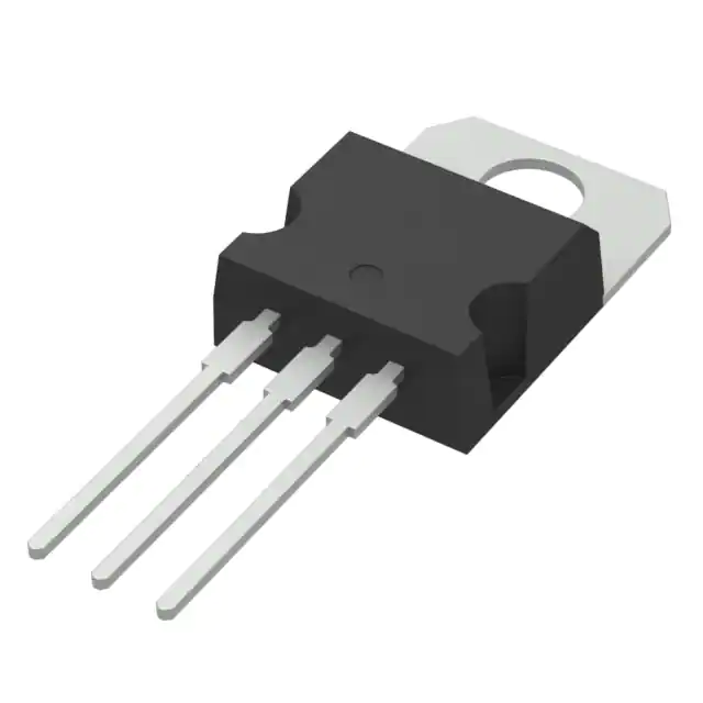


 工商网监
湘ICP备2023018690号
工商网监
湘ICP备2023018690号
