LED2001
Datasheet
4 A monolithic step-down current source with synchronous rectification
Features
•
•
•
•
•
•
•
3.0 V to 18 V operating input voltage range
850 kHz fixed switching frequency
100 mV typ. current sense voltage drop
PWM dimming
± 7% output current accuracy
Synchronous rectification
95 mΩ HS/ 69 mΩ LS typical RDS(on)
•
•
•
•
•
Peak current mode architecture
Embedded compensation network
Ceramic output capacitor compliant
Internal current limiting
Thermal shutdown
Applications
•
•
•
•
Product status link
LED2001
High brightness LED driving
Signage
Halogen bulb replacement
General lighting
Description
The LED2001 is an 850 kHz fixed switching frequency monolithic step-down DC-DC
converter designed to operate as precise constant current source with an adjustable
current capability up to 4 A DC. The embedded PWM dimming circuitry features LED
brightness control. The regulated output current is set connecting a sensing resistor
to the feedback pin. The embedded synchronous rectification and the 100 mV typical
RSENSE voltage drop enhance the efficiency performance.
The size of the overall application is minimized thanks to the high switching
frequency and ceramic output capacitor compatibility. The device is fully protected
against thermal overheating, overcurrent and output short-circuit. The LED2001 is
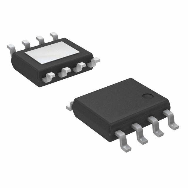
available in VFQFPN 4x4 mm 8-lead package, and HSOP8.
DS9524 - Rev 3 - August 2021
For further information contact your local STMicroelectronics sales office.
www.st.com
�LED2001
Typical application circuit
1
Typical application circuit
Figure 1. Typical application circuit
LED2001
L
VIN
DIM
6
VIN_SW
1
VIN_A
2
DIM
PGND EP
CIN
CFLT
8
9
SW
7
FB
AGND
3
4
RS
COUT
GND
AM12892v1
DS9524 - Rev 3
page 2/40
�LED2001
Pin settings
2
Pin settings
2.1
Pin connection
Figure 2. Pin connection (top view)
2.2
Pin description
Table 1. Pin description
VFQFPN8 4x4 mm
HS0P8
Type
1
1
VINA
Analog circuitry power supply connection
2
2
DIM
Dimming control input. Logic low prevents the switching activity, logic
high enables it. A square wave on this pin implements LED current
PWM dimming. Connect to VINA if not used (see Section 6.6 Dimming
operation)
3
3
FB
Feedback input. Connect a proper sensing resistor to set the LED current
4
4
AGND
5
-
NC
6
6
VINSW
7
7
SW
8
8
PGND
Exposed pad
DS9524 - Rev 3
Description
Analog circuitry ground connection
Not connected
Power input voltage
Regulator switching pin
Power ground
Exposed pad Exposed pad Connect the exposed pad to AGND
page 3/40
�LED2001
Maximum ratings
3
Maximum ratings
Table 2. Absolute maximum ratings
Symbol
Parameter
Value
Unit
VINSW
Power input voltage
-0.3 to 20
V
VINA
Input voltage
-0.3 to 20
V
VDIM
Dimming voltage
-0.3 to (VINA)
V
VSW
Output switching voltage
-1 to VIN
V
VPG
Power Good
-0.3 to VIN
V
VFB
Feedback voltage
-0.3 to 2.5
V
IFB
FB current
-1 to +1
mA
PTOT
Power dissipation at TA < 60 °C
2
°C
TOP
Operating junction temperature range
-40 to 150
°C
TSTG
Storage temperature range
-55 to 150
°C
Table 3. Thermal data
Symbol
Rth JA
Parameter
Maximum thermal
resistance junctionambient(1)
Value
Unit
40
°C/W
VFQFPN8 4x4
HSOP8
1. Package mounted on the evaluation board.
DS9524 - Rev 3
page 4/40
�LED2001
Electrical characteristics
4
Electrical characteristics
TJ = 25 °C, VCC = 12 V, unless otherwise specified.
Table 4. Electrical characteristics
Symbol
Parameter
Operating input voltage range
VIN
Test conditions
(1)
Min.
Typ.
3
Max.
18
Device ON level
2.6
2.75
2.9
Device OFF level
2.4
2.55
2.7
Tj=25 °C (1)
90
97
104
Tj= 125 °C
90
100
110
VFB
feedback Voltage
IFB
VFB pin bias current
RDS(on)-P
High-side switch on-resistance
RDS(on)-N
Low-side switch on-resistance
ILIM
Maximum limiting current
(1)
600
95
ISW=750 mA
V
mV
nA
mΩ
69
(2)
Unit
5.6
A
Oscillator
fSW
D
Switching frequency
0.7
(2)
Duty cycle
0.85
0
1
MHz
100
%
2.5
mA
DC characteristics
IQ
Quiescent current
1.5
Dimming
VDIM
DIM threshold voltage
IDIM
DIM current
Switching activity
1.2
Switching activity prevented
0.4
V
2
µA
1
ms
Soft-start
TSS
Soft-start duration
Protection
TSHDN
Thermal shutdown
150
Hysteresis
15
°C
1. Specifications referred to TJ from -40 to +125 °C. Specifications in the -40 to +125 °C temperature range are
assured by design, characterization and statistical correlation.
2. Guaranteed by design.
DS9524 - Rev 3
page 5/40
�LED2001
Functional description
5
Functional description
The LED2001 is based on a “peak current mode” architecture with fixed frequency control. As a consequence
the intersection between the error amplifier output and the sensed inductor current generates the control signal to
drive the power switch.
The main internal blocks shown in the block diagram in Figure 3. LED2001 block diagram are:
•
High-side and low-side embedded power element for synchronous rectification
•
A fully integrated sawtooth oscillator with a typical frequency of 850 kHz
•
A transconductance error amplifier
•
A high-side current sense amplifier to track the inductor current
•
A pulse width modulator (PWM) comparator and the circuitry necessary to drive the internal power element
•
The soft-start circuitry to decrease the inrush current at power-up
•
The current limitation circuit based on the pulse-by-pulse current protection with frequency divider
•
The dimming circuitry for output current PWM
•
The thermal protection function circuitry
Figure 3. LED2001 block diagram
V I N SW
VI N A
OCP
REF
OSC
I2 V
COMP
I _ SENSE
RSENSE
REGULATOR
UVLO
Vdrv_p
OCP
MOSFET
CONTROL
LOGIC
Vsum
Vc
PWM
DRIVER
Vdrv _n
SW
OTP
DMD
E/A
DIMMING
DRIVER
SOFT-START
0.1V
FB
DIM
GNDA
GNDP
AM12894v1
5.1
Power supply and voltage reference
The internal regulator circuit consists of a start-up circuit, an internal voltage pre-regulator, the bandgap voltage
reference and the bias block that provides current to all the blocks. The starter supplies the start-up current to the
entire device when the input voltage goes high and the device is enabled. The pre-regulator block supplies the
bandgap cell with a pre-regulated voltage that has a very low supply voltage noise sensitivity.
DS9524 - Rev 3
page 6/40
�LED2001
Voltage monitor
5.2
Voltage monitor
An internal block continuously senses the Vcc, Vref and Vbg. If the monitored voltages are good, the regulator
begins operating. There is also a hysteresis on the Vcc (UVLO).
Figure 4. Internal circuit
VCC
PREREGULATOR
STARTER
VREG
BANDGAP
IC BIAS
VREF
5.3
AM13488v1
Soft-start
The start-up phase is implemented ramping the reference of the embedded error amplifier in 1 ms typ. time. It
minimizes the inrush current and decreases the stress of the power components at power up.
During normal operation a new soft-start cycle takes place in case of:
•
thermal shutdown event
•
UVLO event
The soft-start is disabled when DIM input goes high in order to maximize the dimming performance.
DS9524 - Rev 3
page 7/40
�LED2001
Error amplifier
5.4
Error amplifier
The voltage error amplifier is the core of the loop regulation. It is a transconductance operational amplifier whose
non-inverting input is connected to the internal voltage reference (100 mV), while the inverting input (FB) is
connected to the output current sensing resistor. The error amplifier is internally compensated to minimize the
size of the final application.
Table 5. Uncompensated error amplifier characteristics
Description
Values
Transconductance
220 µS
Low frequency gain
96 dB
CC
195 pF
RC
70 kΩ
The error amplifier output is compared with the inductor current sense information to perform PWM control.
5.5
Thermal shutdown
The shutdown block generates a signal that disables the power stage if the temperature of the chip goes higher
than a fixed internal threshold (150 ± 10 °C typical). The sensing element of the chip is close to the PDMOS area,
ensuring fast and accurate temperature detection. A 15 °C typical hysteresis prevents the device from turning ON
and OFF continuously during the protection operation.
DS9524 - Rev 3
page 8/40
�LED2001
Application notes
6
Application notes
6.1
Closing the loop
Figure 5. Block diagram of the loop
GCO(s)
VIN
PWM control
Current sense
HS
switch
L
VOUT
LC filter
LS
switch
COUT
error
PWM
+
amplifier
VCONTROL
+
comparator
RC
FB
VREF
RS
compensation
CC
network
α LED
AO(s)
AM13490v1
6.2
GCO(s) control to output transfer function
The accurate control to output transfer function for a buck peak current mode converter can be written as follows:
Equation 1
1 + Ws
1
z
R
0
s
GCO =
⋅
⋅ FH s
⋅
Ri 1 + R0 ⋅ TSW ⋅ m ⋅ 1 − D − 0.5
s
1
+
C
L
Wp
where R0 represents the load resistance, Ri the equivalent sensing resistor of the current sense circuitry , ωp the
single pole introduced by the LC filter and ωz the zero given by the ESR of the output capacitor.
FH(s) accounts the sampling effect performed by the PWM comparator on the output of the error amplifier that
introduces a double pole at one half of the switching frequency.
Equation 2
1
ω z = ------------------------------ESR . C OUT
where ESR is the equivalent series resistor to the output capacitor.
Equation 3
DS9524 - Rev 3
page 9/40
�LED2001
Error amplifier compensation network
m C . ( 1 – D ) – 0.5
1
ωP = -------------------------------------- + --------------------------------------------L . C OUT . f SW
R LOAD . C OUT
where:
Equation 4
S
mC = 1 + Se
n
Se = Vpp ⋅ fsw
V −V
Sn = IN L OUT ⋅ Ri
Sn represents the slope of the sensed inductor current, Se the slope of the external ramp (VPP peak to peak
amplitude equal to 1.2 V) that implements the slope compensation to avoid sub-harmonic oscillations at duty
cycle over 50%.
The sampling effect contribution FH(s) is:
Equation 5
1
F H ( s ) = ------------------------------------------2
s
s
1 + ------------------- + -----ωn . Q P ω2
n
where:
Equation 6
ωn = π . f SW
and
Equation 7
1
Q P = ---------------------------------------------------------π . [mC . ( 1 – D ) – 0.5]
6.3
Error amplifier compensation network
The LED2001 embeds ( see figure below) the error amplifier and a pre-defined compensation network, which
stabilize the system in most application conditions.
DS9524 - Rev 3
page 10/40
�LED2001
Error amplifier compensation network
Figure 6. Transconductance embedded error amplifier
+
E/A
COMP
-
FB
RC
CP
CC
V+
R0
dV
Gm dV
C0
RC
CP
CC
AM13491v1
RC and CC introduce a pole and a zero in the open loop gain. CP does not significantly affect system stability but it
can be useful to reduce the noise at the output of the error amplifier.
The transfer function of the error amplifier and its compensation network is:
Equation 8
A V0 . ( 1 + s . R c . C c )
A 0 ( s ) = ----------------------------------------------------------------------------------------------------------------------------------------------------------------------------------------2
s . R0 . ( C0 + Cp ) . Rc . Cc + s . ( R0 . Cc + R0 . ( C0 + Cp ) + Rc . Cc ) + 1
Where AV0 = Gm · R0.
The poles of this transfer function are (if Cc >> C0 + CP):
Equation 9
1
f P LF = ---------------------------------2 . π . R0 . Cc
Equation 10
1
f P HF = ---------------------------------------------------2 . π . Rc . ( C0 + Cp )
whereas the zero is defined as:
Equation 11
1
F Z = --------------------------------2 . π . Rc . Cc
The embedded compensation network is RC=70 K, CC=195 pF while CP and CO can be considered as negligible.
The error amplifier output resistance is 240 MΩ, so the relevant singularities are:
Equation 12
fz = 11.6 kHz
fPLF = 3.4 Hz
DS9524 - Rev 3
page 11/40
�LED2001
LED small signal model
6.4
LED small signal model
Once the system reaches the working condition, LEDs composing the row are biased and their equivalent circuit
can be considered as a resistor for frequencies
很抱歉,暂时无法提供与“LED2001PHR”相匹配的价格&库存,您可以联系我们找货
免费人工找货- 国内价格 香港价格
- 1+26.567201+3.42960
- 10+19.9074010+2.56990
- 25+18.2425025+2.35500
- 100+16.39790100+2.11690
- 250+15.52350250+2.00400
- 500+15.26000500+1.97000
- 1000+14.469401000+1.86790
- 2500+13.942402500+1.79990
- 5000+13.678905000+1.76590
- 国内价格
- 1+38.72290
- 10+32.26910
- 30+25.81520
- 100+21.51270
- 国内价格
- 2500+17.19637
- 12500+16.85168