S3AF THRU S3MF
SURFACE MOUNT GENERAL RECTIFIER
Reverse Voltage - 50 to 1000 Volts
FEATURES
SMAF
The plastic package carries Underwriters Laboratory
Flammability Classification 94V-0
For surface mounted applications
Low reverse leakage
Built-in strain relief,ideal for automated placement
High forward surge current capability
Glass passivated chip junction
Cathode Band
Top View
0.110(2.80)
0.094(2.40)
Forward Current - 3.0 Amperes
0.059(1.50)
0.051(1.30)
0.144(3.65)
0.128(3.25)
0.012(0.30)
0.006(0.15)
0.055(1.40)
0.043(1.10)
0.047(1.20)
0.028(0.70)
MECHANICAL DATA
0.189(4.80)
0.173(4.40)
Dimensions in inches and (millimeters)
Case: JEDEC SMAF molded plastic body over passivated chip
Terminals: Solder plated, solderable per MIL-STD-750,
Method 2026
Polarity: Color band denotes cathode end
Mounting Position: Any
Weight:0.0018 ounce, 0.064 grams
MAXIMUM RATINGS AND ELECTRICAL CHARACTERISTICS
Ratings at 25 C ambient temperature unless otherwise specified.
Single phase half-wave 60Hz,resistive or inductive load,for capacitive load current derate by 20%.
MDD Catalog Number
SYMBOLS
Maximum repetitive peak reverse voltage
Maximum RMS voltage
Maximum DC blocking voltage
Maximum average forward rectified current
at TL=75 C
Peak forward surge current
8.3ms single half sine-wave superimposed on
rated load (JEDEC Method)
Maximum instantaneous forward voltage at 3.0A
Maximum DC reverse current
TA=25 C
at rated DC blocking voltage
TA=125 C
Typical junction capacitance (NOTE 1)
VRRM
VRMS
VDC
Typical thermal resistance (NOTE 2)
RθJA
Operating junction and storage temperature range
50
35
50
100
70
100
S3DF S3GF
200
140
200
400
280
400
S3JF
S3KF
S3MF
UNITS
600
420
600
800
560
800
1000
700
1000
VOLTS
VOLTS
VOLTS
I(AV)
3.0
Amps
IFSM
100.0
Amps
VF
1.2
Volts
IR
5.0
250.0
µA
53.0
13.0
47.0
pF
C/W
-50 to +150
C
CJ
TJ,TSTG
Note:1.Measured at 1MHz and applied reverse voltage of 4.0V D.C.
2.P.C.B. mounted with 0.2x0.2”(5.0x5.0mm) copper pad areas
2014-03 01版
S3AF S3BF
�RATINGS AND CHARACTERISTIC CURVES S3AF THRU S3MF
Fig.2 Typical Instaneous Reverse
Characteristics
3.0
2.4
1.8
1.2
0.6
Single phase half-wave 60 Hz
resistive or inductive load
0.0
25
50
75
100
125
150
175
Instaneous Reverse Current ( μ A)
Average Forward Current (A)
Fig.1 Forward Current Derating Curve
100
T J =150°C
T J =125°C
10
T J =100°C
1.0
T J =75°C
T J =50°C
0.1
T J =25°C
0.01
0
Junction Capacitance ( pF)
2 5°
C
TJ =
°C
00
TJ
=1
50
°C
0.5
=1
600
800
Fig.4 Typical Junction Capacitance
1.0
TJ
Instaneous Forward Current (A)
Fig.3 Typical Forward Characteristic
0.2
0.1
0.6
400
200
Instaneous Reverse Voltage (V)
Ambient Temperature (°C)
100
10
T J =25°C
1
0.7
0.8
0.9
1.0
Instaneous Forward Voltage (V)
2014-03 01版
1.1
0.1
1.0
10
Reverse Voltage (V)
100
�
很抱歉,暂时无法提供与“通用二极管/S3MF”相匹配的价格&库存,您可以联系我们找货
免费人工找货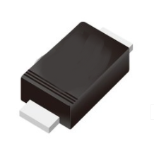


 工商网监
湘ICP备2023018690号
工商网监
湘ICP备2023018690号
