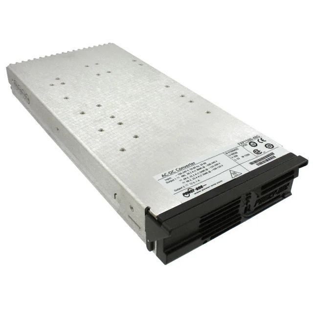
The FXP1500/1800 front-ends are power-factor-corrected (PFC) and
provide a 48 VDC (1500 or 1800 watt) output, and can be used in hot-swap
redundant systems. Their very small dimensions allow configuration of up
to three units in a 1U rack. The FXP front-ends have a rear-mounted AC
connector. The highly efficient thermal design with internal-fan cooling
permits their use over wide temperature ranges and provides very high
reliability.
Status information is provided with front panel LEDs, logic signals, and via
an I2C management interface. In addition, the I2C bus can enable the power
supply, set high fan speed, adjust the output voltage, and set the output
current limit. The FXP1500/1800's meet international safety standards and
display the CE-Mark for the European Low Voltage FXR-3-48G powershelf solutions provide rectification, system management, and power
distribution, while maintaining high reliability and offering flexibility for
future expansion. The power shelves can be configured with up to three
hot-swappable 1500 or 1800-watt AC-DC front-ends.
RoHS compliant for all six substances
High density front-ends 15.2 to 18.3 W/in3
Wide input voltage range 85 to 264 VAC
12 V standby voltage, 1 A per front-end
Highly efficient topology reduces operating costs
I2C interface status and control
I2C voltage and current limit setting
Analog output voltage setting
Overtemperature, output overvoltage, and output
overcurrent protection
ORing circuits for true redundant operation:
Vo1: ORing FETs; Vo2: ORing Diodes
Status LEDs: AC OK, DC OK, and
Fan Fail/Overtemperature Fail
Telecommunications
Data Communications
Servers
Distributed Power
�FXP1500/1800; FXR-3-48G
2
MODEL
FXP1500-48G
FXP1800-48G
1
INPUT VOLTAGE
VAC
AUTO SELECTED 1
105 – 264
85 – 105
180 – 264
105 – 180
85 – 105
OUTPUT 1
OUTPUT 2
Vo1 nom
Io1 max
Vo2 nom
Io2 max
VDC
48
48
48
48
48
ADC
32.2
25.4
39.2
32.2
25.4
VDC
12
12
12
12
12
ADC
1
1
1
1
1
RATED POWER
W
1512
1212
1812
1512
1212
COMPATIBLE
SHELF 2
FXR-3-48G
FXR-3-48G
The available output power is automatically adjusted depending on the input voltage.
1U standard racks are available from Bel Power Solutions. See the Rack (Power Shelf) section of this data sheet for configurations
and details.
2
Stress in excess of the absolute maximum ratings may cause performance degradation, adversely affect long-term
reliability, or cause permanent damage to the converter.
PARAMETER
Input Voltage
CONDITIONS / DESCRIPTION
Continuous
Transient, 60 ms max.
Vi min-Vi max, Io nom, cooling by internal fan
Operating Ambient Temperature
Storage Temperature
MIN
@ 100 % load
@ 50 % load
MAX
264
300
0
0
-40
Non-Operating
UNIT
VAC
50
70
85
°C
°C
Specification is valid for input voltage, load, and temperature ranges, unless otherwise stated.
PARAMETER
MIN
NOM
MAX
UNIT
Input Voltage
CONDITIONS / DESCRIPTION
85
230
264
VAC
Input Frequency
47
50/60
63
Hz
Turn-On Input Voltage
Ramping up
79
85
VAC
Turn-Off Input Voltage
70
78
VAC
50
Hold-Up Time
Ramping down
115/230 VAC acc. ETS 300 132-1
< 100 ms
After last AC line peak ,Vi = 230 VAC, Po nom
Apk
ms
Power Factor
Vi nom, Io nom
Efficiency
Vi = 230 VAC, Io nom, TC = 25 °C
Inrush Current Limitation
20
0.95
89
Max Input Current
Input Connector
W/VA
90
%
20
16 A – 20 A / 250 VAC; according to IEC320 C19
tech.support@psbel.com
Arms
�FXP1500/1800; FXR-3-48G
3
Specification is valid for input voltage, load, and temperature ranges, unless otherwise stated.
PARAMETER
CONDITIONS / DESCRIPTION
Nominal Output Voltage Vo1
Io = 16.1 A
48
VDC
Nominal Output Voltage Vo2
Io = 0.5 A
Vi = 230 VAC, Io1 =16.1 A, TC = 25 °C
12
VDC
Output Voltage Set Point Accuracy
(47.8 - 48.2 VDC)
Output Voltage Trimming
(via I2C or with external resistor)
Adjustable (44.16 to 51.84 VDC)
@ Vi =105 VAC – 264 VAC,
@ Vi = 85 VAC – 105 VAC,
@ Vi =180 VAC – 264 VAC,
FXP1800-48G
@ Vi =105 VAC – 180 VAC,
@ Vi = 85 VAC – 105 VAC,
@ Vi = 105 VAC – 264 VAC
FXP1500-48G
@ Vi = 85 VAC – 105 VAC
Io1 max @ Vi = 180 VAC – 264 VAC
FXP1800-48G Io1 max @ Vi = 105 VAC – 180 VAC
Io1 max @ Vi = 85 VAC – 105 VAC
Io2 nom @ Vi = 85 VAC – 264 VAC,
FXP1500-48G
Nominal Current Output 1
Current Limit Output 1
Nominal Current Output 2
MIN
Io1 nom
Io1 nom
Io1 nom
Io1 nom
Io1 nom
Io1 max
Io1 max
MAX
+0.5
% Vo1 nom
-8
+8
% Vo1 nom
Po 1.5 kW
Po 1.2 kW
Po 1.8 kW
Po 1.5 kW
Po 1.2 kW
32.2
25.4
39.2
32.2
25.4
36.8
30
43.8
36.8
30
1.0
droop hiccup
droop hiccup
droop hiccup
droop hiccup
droop hiccup
Po 12 W
39.2
1.0
1.5
Vi min - Vi max, 50 % Io nom
Vi = 230 V, 5-100 % Io nom
FXP1500-48G
Static Load Regulation
Vo : full load (32.2 ADC) to no load
Output 1
Vi = 230 V, 5-100 % Io nom
(Droop Characteristic)
FXP1800-48G
Vo : full load (32.2 ADC) to no load
Static Load Regulation Output 2
Vi = 230 V, 5-100 % Io nom
(Droop Characteristic)
Vo : full load (32.2 ADC) to no load
Load change 50 % 100 % Io nom, dIo/dt =1 A/s
Static Line Regulation Output 1
UNITS
-0.5
Io2 max @ Vi = 85 VAC – 264 VAC
Current Limit Output 2
NOM
ADC
-0.5
46.65
46.07
0.5
83.5
48
83.5
48
ADC
ADC
ADC
ADC
ADC
ADC
ADC
ADC
ADC
ADC
ADC
49.34
49.34
0.4
% Vo nom
mV/A
VDC
mV/A
VDC
VDC
Voltage deviation (droop + over- or undershoot)
Dynamic Load Regulation
FXP1500-48G
-5
5
% Vo nom
FXP1800-48G
-5.7
5.7
% Vo nom
400
s
FXP1500-48G
3.2
ADC
FXP1800-48G
3.9
ADC
1.5
s
ms
480
120
500
mVpp
mVpp
mV
MAX
UNIT
All models
Current Share
Max. recovery time to within 1 % of Vo1 nom
Difference in current between two units for Vo1 above
10 % load.
Time required for output within regulation
after initial application of AC-input (Vi nom, Io nom)
after removal of inhibit
(Vi nom, Io nom)
Vi nom, Io nom, 20 MHz bandwidth
Start-Up Time
Output Voltage Ripple and Noise
(Filter 10 nF/10 µF)
Vo1
Vo2
Remote Sense
Total compensation for cable losses
PARAMETER
CONDITIONS/DESCRIPTION
Input Fuse
Not user accessible
MIN
With NTCs
Output
Overtemperature Protection
3
NOM
25 A, fast blow
Inrush Current Limitation
Overvoltage Protection Latching
100
3
No-load -, short circuit - and overload proof
115
122
% Vo nom
59.5
V
95
°C
Tracking
Absolute
Automatic power shutdown at TC
Remove input voltage to reset.
Europe, Middle East
+353 61 225 977
North America
+1 408 785 5200
© 2016 Bel Power Solutions & Protection
BCD.00023_AD
Asia-Pacific
+86 755 298 85888
�FXP1500/1800; FXR-3-48G
4
Specification is valid for input voltage, load, and temperature ranges, unless otherwise stated.
PARAMETER
TYPE4
Visual Status Indication
FP
I2C Communication Bus
OC[S1, S2]
I2C Communication Bus
Addressing
OC[T1-T5]
PS Present Pin
PS Main Output Remote
Shutdown
OC[U3]
OC[R1]
FP
Power Supply OK
I2C
DC Current Fail
I2C
AC Fail / Power Down
Warning
OC[U2]
& I2C
DC Fail / Output Voltage
Fault
OC[U4]
& I2C
Critical Temperature
Warning/Fan Fail
OC[U1]
& I2C
DC Voltage Monitoring
I2C
DC Current Monitoring
I2C
DC Voltage Trimming
(Margining)
OC[R4]
Fan Speed Control
2
IC
2
IC
CONDITIONS / DESCRIPTION
•
DC OK (green)
LED indicators5 :
•
AC OK (green)
•
Fan fail & Over-temperature (amber)
• Monitors alarm functions and allows control of specific parameters.
• Uses standard Philips two wire bus (SCL and SDA signal lines)
Five lines provide up to 32 separate PSU I2C addresses
•
Used by system to indicate a PSU is installed in a system shelf
•
Contact closure to logic ground ( internal pull-down resistor of 1 kΩ)
•
TTL compatible signal, inhibited when open contact, high or at TTL logic “1”
•
Signal referenced to logic return (LRTN)
Two position switch in series with OC signal (logical AND) allows local enable/disable; “0” Position
=> PS disabled; “1” Position => PS Enabled
AC OK & DC OK & no overcurrent & no over-temperature & fans working
Reports over-current condition on main output, IO1
Provides a warning that the input power has failed at least 5 ms before the output falls out of
regulation ( 110% of VO1 set, measured in front of the
ORing FETs.
•
Green LED on the front panel indicates normal operation; LED will flash if in parallel
operation VO1 is OK, but the unit is disabled.
Indicates the PSU operating temperature has reached [Tshut-down – 10K] Indicates if the unit is in
over-temperature shutdown.
•
Open collector signal with 20 mA pull-down capability, referenced to logic return (LRTN).
•
The OC-output will go low 100 ms before an over-temperature condition shuts down the
unit.
•
An amber LED on the front panel indicates over-temperature or fan fail.
Monitors the main output voltage, VO1, seen at the output connector.
Accuracy is ±0.45V over setting range and temperature.
Monitors the output current IO1: Accuracy ± 0.4A over the load range.
Output voltage trimming VO1 : ±8% of VO set using external resistor
Setting accuracy over I2C: ± 50mV at Vo1nom, ± 150mV over setting range
Two fan speed levels automatically set depending on the internal temperature. The fan speed can
be set to full speed or automatic control via I2C command.
Fan OK/FAIL
OC[U1]
& I2C
Indicates if the cooling fans are operating or have failed.
Synchronized Startup Pin
OC[R5]
Overcurrent signal which can be used for synchronous startup of units in parallel or to recover
from an overload condition.
4
5
Abbreviations used:
OC[#]
=> Hardwired signal accessible at PSU output connector, with pin number reference
FP
=> Provided by devices located on PSU Front panel
I2C
=> Signal provided over I2C communication system; detailed I2C information is available from the specific
model’s I2C Manual found on the Bel Power Solutions web site.
See LED Function table for further details
tech.support@psbel.com
�FXP1500/1800; FXR-3-48G
PARAMETER
Altitude
Relative Humidity, Non-Condensing
5
CONDITIONS / DESCRIPTION
Operating
Non-Operating
Operating
MIN
Storage
Temperature Coefficient
0 °C to 70 °C (after 15 min warm-up)
Shock
IEC/EN 60068-2-27, 11 ms
IEC/EN 60068-2-6
2-8 Hz
8-200 Hz
200-500 Hz
10-2000 Hz
Calculated per Bellcore (SR-332, Issue 1):
GB 25 °C
GB 25 °C (FNP1500-12G)
Demonstrated
Sinusoidal Vibration
Random Vibration
MTBF
NOM
ASL Ft.
10
MAX
10 k
40 k
90
UNIT
5
95
% RH
0.02
%/K
40
gpk
% RH
7.5
2
4
6.15
mil
gpk
gpk
grms
230
TBD
250
kh
Maximum electric strength testing is performed in the factory according to EN50514, IEC/EN60950-1 2nd ed. and
UL/CSA60950-1 2nd ed. Input-to-output electric strength tests should not be repeated in the field. Bel Power Solutions will
not honor any warranty claims resulting from electric strength field tests.
PARAMETER
Agency Approvals
Insulation Safety Rating
Electric Strength Test Voltage
6
CONDITIONS / DESCRIPTION
Approved to latest edition of the following standards:
UL/CSA60950-1, IEC60950-1 and EN60950-1.
CE Mark for LVD
Input to case
Input to output
Output to case
Input to case
Input to output
Output to case
Output 1 to output 2
MIN
NOM
MAX
UNIT
Basic
Reinforced
Functional
2.12
4.2 6
0.5
0.1
kVDC
kVDC
kVDC
kVDC
Subassemblies are pre-tested with 4.2 kVDC in accordance with EN50514 and IEC/EN60950-1 2nd ed.
PARAMETER
DESCRIPTION
CRITERION
Electrostatic Discharge
IEC/EN 61000-4-2, level 4
Performance criterion B
Electromagnetic Field
IEC/EN 61000-4-3, level 3
Performance criterion A
Electrical Fast Transients/Burst
IEC/EN 61000-4-4, level 3
Performance criterion B
Surge
IEC/EN 61000-4-5, level 3
Performance criterion B
Voltage Dips and Interruptions
IEC/EN 61000-4-11
RF Conducted Immunity
IEC/EN 61000-4-6
Emissions Conducted
CISPR 22/EN 55022/EN 61204
Emissions Radiated
CISPR 22/EN 55022/EN 61204
Class A
Harmonics
IEC/EN 61000-3-2
Class B
Voltage Fluctuation and Flicker
IEC/EN 61000-3-3
Pass
Voltage Sag
SEMI F47-0200 (High Line 230 V)
Pass
Performance criterion B or better
10 VAC, AM 80 %, 1 kHz
Performance criterion A
Class B
Europe, Middle East
+353 61 225 977
North America
+1 408 785 5200
© 2016 Bel Power Solutions & Protection
BCD.00023_AD
Asia-Pacific
+86 755 298 85888
�FXP1500/1800; FXR-3-48G
6
OUTPUT CONNECTOR
DESCRIPTION
Over-temperature /
Fan Fail
AC Fail /
Power down warning
OC
PIN #
U1
U2
Power Supply Present
U3
DC Fail /
Output voltage fault
U4
Internal ground
(INT GND)
U5
ADDR0 I2C address bus
T1
ADDR1 I2C address bus
T2
2
ADDR2 I C address bus
SIGNAL
REFERENCE
TYPE
LOW LEVEL
HIGH LEVEL