Product
Folder
Sample &
Buy
Support &
Community
Tools &
Software
Technical
Documents
bq24765
SLUS999A – NOVEMBER 2009 – REVISED NOVEMBER 2015
bq24765 SMBus-Controlled Multi-Chemistry Battery Charger With Integrated Power
MOSFETs
1
1 Features
•
•
•
•
•
•
•
•
•
•
•
•
•
Integrated Power MOSFETs, NMOS-NMOS,
Synchronous Buck Converter
>95% Efficiency
Frequency 700kHz Allows Smaller Inductor (5 mm
x 5 mm)
Thermal Regulation Loop for Safety, Limit TJ =
120°C
Adaptive Driver Dead-time and 99.5% Maximum
Effective Duty Cycle
High-Accuracy Voltage and Current Regulation
– ±0.5% Charge Voltage Accuracy
– ±3% Charge Current Accuracy
– ±3% Adapter Current Accuracy
– ±2% Input Current Sense Amp Accuracy
Integration
– Integrated Power MOSFETs
– Input Current Comparator
– Internal Soft-Start
Safety
– Thermal Regulation Loop and Thermal
Shutdown
– Dynamic Power Management (DPM)
– Power FETs Over Current Protection
7 V–24 V AC/DC-Adapter Operating Range
Simplified SMBus Control
– Charge Voltage DAC (1.024 V–19.2 V)
– Charge Current DAC (128 mA–8.064 A)
– Adapter Current Limit DPM DAC (256
mA–11.008 A)
Status and Monitoring Outputs
– AC/DC Adapter Present With Adjustable
Voltage Threshold
– Input Current Comparator, With Adjustable
Threshold and Hysteresis
– Current Sense Amplifier for Current Drawn
From Input Source
Charge Any Battery Chemistry: Li+, LiFePO4,
NiCd, NiMH, Lead Acid (2, 3, and 4 Li-Ion Cells)
Charge Enable Pin (CE)
Energy Star Low Iq
– < 10-μA Battery Current with Adapter
Removed
– < 1 mA Input DCINA Current When Adapter
•
Present and Charge Disabled
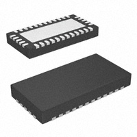
34-pin, 3.50 mm × 7.00 mm QFN Package
2 Applications
•
•
•
•
•
•
Notebook and Ultra-Mobile Computers
Portable Data-Capture Terminals
Portable Printers
Medical Diagnostics Equipment
Battery Bay Chargers
Battery Back-up Systems
3 Description
The bq24765 is a high-efficiency, synchronous
battery charger with two integrated 30-mΩ NMOS
power MOSFETs, and an integrated input current
comparator, offering low component count for spaceconstraint,
multi-chemistry
battery
charging
applications. Input current, charge current, and
charge voltage DACs allow for very high regulation
accuracies that can be easily programmed by the
system power management micro-controller using
SMBus. The bq24765 has switching frequency of 700
kHz. The bq24765 charges 2, 3, or 4 series Li+ cells,
and is available in a 34-pin, 3.50 mm x 7.00 mm
VQFN package.
Device Information(1)
PART NUMBER
bq24765
PACKAGE
VQFN (34)
BODY SIZE (NOM)
3.50 mm × 7.00 mm
(1) For all available packages, see the orderable addendum at
the end of the data sheet.
Simplified Schematic
ADAPTER
SYSTEM
Control by
host
CSSP
CSSN
ACIN
ICREF
SMBUS
Host GPIO
ADC
SDA
SCL
CE
ACOK
ICOUT
VICM
Control by
host
DCINP
VDDSMB
VREF
AGND
DCINA
PHASE
BOOT
bq24765
•
PowerPad
ADDP
Battery
pack
PGND
CSOP
CSON
VFB
EAO
EAI
FBO
1
An IMPORTANT NOTICE at the end of this data sheet addresses availability, warranty, changes, use in safety-critical applications,
intellectual property matters and other important disclaimers. PRODUCTION DATA.
�bq24765
SLUS999A – NOVEMBER 2009 – REVISED NOVEMBER 2015
www.ti.com
Table of Contents
1
2
3
4
5
6
7
Features ..................................................................
Applications ...........................................................
Description .............................................................
Revision History.....................................................
Description (Continued) ........................................
Pin Configuration and Functions .........................
Specifications.........................................................
7.1
7.2
7.3
7.4
7.5
7.6
7.7
8
1
1
1
2
3
3
5
Absolute Maximum Ratings ...................................... 5
ESD Ratings.............................................................. 5
Recommended Operating Conditions....................... 6
Thermal Information .................................................. 6
Electrical Characteristics........................................... 7
SMB Timing Requirements ..................................... 10
Typical Characteristics ............................................ 12
Detailed Description ............................................ 14
8.1 Overview ................................................................. 14
8.2 Functional Block Diagram ....................................... 15
8.3 Feature Description................................................. 16
8.4 Device Functional Modes........................................ 21
8.5 Programming........................................................... 21
8.6 Register Maps ......................................................... 25
9
Application and Implementation ........................ 28
9.1 Application Information............................................ 28
9.2 Typical Application ................................................. 28
10 Power Supply Recommendations ..................... 33
11 Layout................................................................... 33
11.1 Layout Guidelines ................................................. 33
11.2 Layout Example .................................................... 34
12 Device and Documentation Support ................. 35
12.1
12.2
12.3
12.4
12.5
12.6
Device Support......................................................
Documentation Support ........................................
Community Resources..........................................
Trademarks ...........................................................
Electrostatic Discharge Caution ............................
Glossary ................................................................
35
35
35
35
35
35
13 Mechanical, Packaging, and Orderable
Information ........................................................... 36
4 Revision History
NOTE: Page numbers for previous revisions may differ from page numbers in the current version.
Changes from Original (November 2009) to Revision A
Page
•
Added ESD Ratings table, Feature Description section, Device Functional Modes, Application and Implementation
section, Power Supply Recommendations section, Layout section, Device and Documentation Support section, and
Mechanical, Packaging, and Orderable Information section .................................................................................................. 1
•
Deleted Ordering Information table ....................................................................................................................................... 1
2
Submit Documentation Feedback
Copyright © 2009–2015, Texas Instruments Incorporated
Product Folder Links: bq24765
�bq24765
www.ti.com
SLUS999A – NOVEMBER 2009 – REVISED NOVEMBER 2015
5 Description (Continued)
The bq24765 features Dynamic Power Management (DPM) and input power limiting. These features reduce
battery charge current when the input power limit is reached to avoid overloading the AC adaptor when supplying
the load and the battery charger simultaneously. A high-accuracy current sense amplifier enables accurate
measurement of input current from the AC adapter, allowing monitoring the overall system power. If the adapter
current is above the programmed low-power threshold, a signal is sent to host so that the system optimizes its
power performance according to what is available from the adapter. An integrated comparator allows monitoring
the input current through the current sense amplifier, and indicating when the input current exceeds a
programmable threshold limit. The bq24765 features a thermal regulation loop to reduce battery charge current
when the Tj limit is reached. This feature protects internal power FETs from overheating when charging with high
current.
6 Pin Configuration and Functions
PGND
PH ASE
PH ASE
34
PGND
PGND
RUV Package
34-Pin VQFN
Top View
33
32
31
30
PGND
1
29 PHASE
DCINP
2
28 PHASE
DCINP
3
27 PHASE
DCINP
4
26 BOOT
CSSN
5
25 DCINA
CSSP
6
24 VDDP
VREF
7
23 ICOUT
ICREF
8
22 CSOP
ACIN
9
21 CSON
EAO 10
EAI
20 VFB
19 AGND
11
18 ACOK
15
CE
SDA
16
17
SC L
14
VDD SMB
13
VICM
FBO 12
Pin Functions
PIN
TYPE
DESCRIPTION
9
I
Adapter detected voltage set input. Program the adapter detect threshold by connecting a resistor divider from
adapter input to ACIN pin to AGND pin. ACOK open-drain output is pulled high and charge is allowed when
ACIN pin voltage is greater than 2.4V. VREF regulator and VICM current sense amplifier are active when
ACIN pin voltage is greater than 0.6V, and DCINA>VDCIN_UVLO.
ACOK
18
O
Valid adapter active-high detect logic open-drain output. Pulled HI when Input voltage is above ACIN
programmed threshold and DCINA is above UVLO threshold. Connect a 10-kΩ pull-up resistor from ACOK
pin to pull-up supply rail.
AGND
19
AGND
BOOT
26
P
PWM high side driver positive supply. Connect a 0.1uF bootstrap ceramic capacitor from BOOT to PHASE.
Connect a small bootstrap Schottky diode from VDDP to BOOT.
CE
13
I
Charge enable active-high logic input. HI enables charge. LO disables charge. Pull up CE using 10kOhm
resistor or connect directly to VREF to enable charger.
CSON
21
P
Charge current sense resistor, negative input. An optional 0.1-uF ceramic capacitor is placed from CSON pin
to AGND for common-mode filtering. A 0.1-uF ceramic capacitor is placed from CSON to CSOP to provide
differential-mode filtering. The capacitor of the output LC filter is placed on CSON.
CSOP
22
P
Charge current sense resistor, positive input. A 0.1-uF ceramic capacitor is placed from CSOP pin to AGND
for common mode filtering. A 0.1-uF ceramic capacitor is placed from CSON to CSOP to provide differentialmode filtering.
NAME
NO.
ACIN
Analog Ground. On PCB layout, connect to the analog ground plane, and only connect to PGND through the
power-pad underneath the IC.
Submit Documentation Feedback
Copyright © 2009–2015, Texas Instruments Incorporated
Product Folder Links: bq24765
3
�bq24765
SLUS999A – NOVEMBER 2009 – REVISED NOVEMBER 2015
www.ti.com
Pin Functions (continued)
PIN
TYPE
DESCRIPTION
5
P
Adapter current sense resistor, negative input. An optional 0.1-uF ceramic capacitor is placed from CSSN pin
to AGND for common-mode filtering. A 0.1-uF ceramic capacitor is placed from CSSN to CSSP to provide
differential-mode filtering.
CSSP
6
P
Adapter current sense resistor, positive input. A 0.1-uF ceramic capacitor is placed from CSSP pin to AGND
for common-mode filtering. A 0.1-uF ceramic capacitor is placed from CSSN to CSSP to provide differentialmode filtering.
DCINA
25
P
Analog sense of IC power positive supply for internal reference bias circuit. Connect directly to adapter input,
or to diode-OR point of adapter and battery. Place a 20Ω and 0.5uF ceramic capacitor filter from adapter to
AGND pin close to the IC and connect to DCINA on the node between the resistor and capacitor.
DCINP
2
P
High current input for IC power positive supply, and connection to drain of high-side power MOSFET. Place
two 10uF ceramic capacitors from DCINP to PGND pin close to the IC.
DCINP
3
P
High current input for IC power positive supply, and connection to drain of high-side power MOSFET. Place
two 10uF ceramic capacitors from DCINP to PGND pin close to the IC.
DCINP
4
P
High current input for IC power positive supply, and connection to drain of high-side power MOSFET. Place
two 10uF ceramic capacitors from DCINP to PGND pin close to the IC.
EAI
11
I
Error Amplifier Input for compensation. Connect the feedback compensation components from EAI to EAO.
Connect the input compensation from FBO to EAI.
EAO
10
I
Error Amplifier Output for compensation. Connect the feedback compensation components from EAO to EAI.
Typically, a capacitor in parallel with a series resistor and capacitor. This node is internally compared to the
PWM saw-tooth oscillator signal.
FBO
12
O
Feedback Output for compensation. Connect the input compensation from FBO to EAI. Typically, a resistor in
parallel with a series resistor and capacitor.
ICOUT
23
O
Low power mode detect active-high open-drain logic output. Place a 10kohm pull-up resistor from ICOUT pin
to the pull-up voltage rail. Place a positive feedback resistor from ICOUT pin to ICREF pin for programming
hysteresis. The output is HI when VICM pin voltage is lower than ICREF pin voltage. The output is LO when
VICM pin voltage is higher than ICREF pin voltage.
ICREF
8
I
Low power voltage set input. Connect a resistor divider from VREF to ICREF, and AGND to program the
reference for the LOPWR comparator. The ICREF pin voltage is compared to the VICM pin voltage and the
logic output is given on the ICOUT open-drain pin. Connecting a positive feedback resistor from ICREF pin to
ICOUT pin programs the hysteresis.
PGND
1
PGND
Power ground. Connection to source of integrated low-side power MOSFET. On PCB layout, connect to
ground connection of input and output capacitors of the charger. Only connect to AGND through the powerpad underneath the IC.
PGND
32
PGND
Power ground. Connection to source of integrated low-side power MOSFET. On PCB layout, connect to
ground connection of in put and out put capacitors of the charger. Only connect to AGND through the powerpad underneath the IC.
PGND
33
PGND
Power ground. Connection to source of integrated low-side power MOSFET. On PCB layout, connect to
ground connection of in put and out put capacitors of the charger. Only connect to AGND through the powerpad underneath the IC
PGND
34
PGND
Power ground. Connection to source of integrated low-side power MOSFET. On PCB layout, connect to
ground connection of in put and out put capacitors of the charger. Only connect to AGND through the powerpad underneath the IC.
PHASE
28
P
Phase switching node (junction of the integrated high-side power MOSFET source and the integrated low-side
power MOSFET drain). Connect to the output inductor. Connect the 0.1uF bootstrap ceramic capacitor from
PHASE to BOOT
PHASE
27
P
Phase switching node (junction of the integrated high-side power MOSFET source and the integrated low-side
power MOSFET drain). Connect to the output inductor. Connect the 0.1uF bootstrap ceramic capacitor from
PHASE to BOOT.
PHASE
29
P
Phase switching node (junction of the integrated high-side power MOSFET source and the integrated low-side
power MOSFET drain). Connect to the output inductor. Connect the 0.1uF bootstrap ceramic capacitor from
PHASE to BOOT
PHASE
30
P
Phase switching node (junction of the integrated high-side power MOSFET source and the integrated low-side
power MOSFET drain). Connect to the output inductor. Connect the 0.1uF bootstrap ceramic capacitor from
PHASE to BOOT.
PHASE
31
P
Phase switching node (junction of the integrated high-side power MOSFET source and the integrated low-side
power MOSFET drain). Connect to the output inductor. Connect the 0.1uF bootstrap ceramic capacitor from
PHASE to BOOT.
NAME
NO.
CSSN
4
Submit Documentation Feedback
Copyright © 2009–2015, Texas Instruments Incorporated
Product Folder Links: bq24765
�bq24765
www.ti.com
SLUS999A – NOVEMBER 2009 – REVISED NOVEMBER 2015
Pin Functions (continued)
PIN
NAME
NO.
TYPE
DESCRIPTION
SCL
16
I
SMBus Clock input. Connect to SMBus clock line from the host controller. A 10-kohm pull-up resistor to the
host controller power rail is needed.
SDA
15
I
SMBus Data input. Connect to SMBus data line from the host controller. A 10-kohm pull-up resistor to the
host controller power rail is needed.
VDDP
24
P
PWM low side driver positive 6V supply output. Connect a 1uF ceramic capacitor from VDDP to PGND pin,
close to the IC. Use for high-side driver bootstrap voltage by connecting a small signal Schottky diode from
VDDP to BOOT.
VDDSMB
17
I
Input voltage for SMBus logic. Connect a 3.3V always supply rail, or 5V always rail to VDDSMB pin. Connect
a 0.1uF ceramic capacitor from VDDSMB to AGND for decoupling.
VFB
20
I
Battery voltage remote sense. Directly connect a Kelvin sense trace from the battery pack positive terminal to
the VFB pin to accurately sense the battery pack voltage. Place a 0.1-uF capacitor from VFB to AGND close
to the IC to filter high frequency noise.
VICM
14
O
Adapter current sense amplifier output. VICM voltage is 20 times the differential voltage across CSSP-CSSN.
Place a 100pF (max) or less ceramic decoupling capacitor from VICM to AGND.
VREF
7
P
3.3V regulated voltage output. Place a 1uF ceramic capacitor from VREF to AGND pin close to the IC. This
voltage could be used for programming the ICREF threshold. VREF can directly connect to VDDSMB as
SMBus supply, or serve as pull up supply rail for CE, ACOK and ICOUT.
GND
Exposed pad beneath the IC. AGND and PGND star-connected only at the Power Pad plane. Always solder
Power Pad to the board, and have vias on the Power Pad plane connecting to AGND and PGND planes. It
also serves as a thermal pad to dissipate heat.
Power
Pad
7 Specifications
7.1 Absolute Maximum Ratings
over operating free-air temperature range (unless otherwise noted) (1) (2)
MIN
MAX
–0.3
30
–1
30
EAI, EAO, FBO, VDDP, ACIN, VICM, ICOUT, ICREF, CE
–0.3
7
VDDSMB, SDA, SCL
–0.3
6
VREF
–0.3
3.6
BOOT (with respect to AGND and PGND)
–0.3
36
DCINP, DCINA, CSOP, CSON, CSSP, CSSN, VFB, ACOK
PHASE
Voltage
UNIT
V
Maximum difference voltage: CSOP–CSON, CSSP–CSSN
–0.5
0.5
V
Operating junction temperature, TJ
-40
155
°C
Storage temperature, Tstg
–55
155
°C
(1)
(2)
Stresses beyond those listed under Absolute Maximum Ratings may cause permanent damage to the device. These are stress ratings
only, which do not imply functional operation of the device at these or any other conditions beyond those indicated under Recommended
Operating Conditions. Exposure to absolute-maximum-rated conditions for extended periods may affect device reliability.
All voltages are with respect to AGND and PGND if not specified. Currents are positive into, and negative out of the specified terminal.
Consult Packaging Section of the data book for thermal limitations and considerations of packages.
7.2 ESD Ratings
VALUE
Human-body model (HBM), per ANSI/ESDA/JEDEC JS-001
V(ESD)
(1)
(2)
Electrostatic discharge
(1)
Charged-device model (CDM), per JEDEC specification JESD22C101 (2)
UNIT
±2000
±500
V
JEDEC document JEP155 states that 500-V HBM allows safe manufacturing with a standard ESD control process.
JEDEC document JEP157 states that 250-V CDM allows safe manufacturing with a standard ESD control process.
Submit Documentation Feedback
Copyright © 2009–2015, Texas Instruments Incorporated
Product Folder Links: bq24765
5
�bq24765
SLUS999A – NOVEMBER 2009 – REVISED NOVEMBER 2015
www.ti.com
7.3 Recommended Operating Conditions
MIN
PHASE
Voltage
NOM
–1
MAX
UNIT
24
DCINP, DCINA, CSOP, CSON, CSSP, CSSN, VFB, ACOK
0
24
VDDP
0
6.5
VREF
3.3
VDDSMB, SDA, SCL
0
5.5
EAI, EAO, FBO, ACIN, VICM, ICOUT, ICREF, CE
0
5.5
V
BOOT (with respect to GND and PGND)
0
30
Maximum difference voltage: CSOP–CSON, CSSP–CSSN
–0.3
0.3
V
Junction temperature
–40
125
°C
Storage temperature
–55
150
°C
7.4 Thermal Information
bq24765
THERMAL METRIC
(1)
RUV (VQFN)
UNIT
34 PINS
RθJA
Junction-to-ambient thermal resistance
33.7
°C/W
RθJC(top)
RθJB
Junction-to-case (top) thermal resistance
23
°C/W
Junction-to-board thermal resistance
6.3
°C/W
ψJT
Junction-to-top characterization parameter
0.3
°C/W
ψJB
Junction-to-board characterization parameter
6.1
°C/W
RθJC(bot)
Junction-to-case (bottom) thermal resistance
1.9
°C/W
(1)
6
For more information about traditional and new thermal metrics, see the Semiconductor and IC Package Thermal Metrics application
report, SPRA953.
Submit Documentation Feedback
Copyright © 2009–2015, Texas Instruments Incorporated
Product Folder Links: bq24765
�bq24765
www.ti.com
SLUS999A – NOVEMBER 2009 – REVISED NOVEMBER 2015
7.5 Electrical Characteristics
7.0 V ≤ V(DCINA) ≤ 24 V, 0°C < TJ < +125°C, typical values are at TA = 25°C, with respect to AGND (unless otherwise noted)
PARAMETER
TEST CONDITIONS
MIN
TYP
MAX
UNIT
OPERATING CONDITIONS
VDCIN_OP
DCINA/DCINP input voltage
operating range
7
24
V
DCINA
V
16.884
V
CHARGE VOLTAGE REGULATION
VVFB_OP
VFB input voltage range
0
16.716
ChargeVoltage() = 0x41A0
VVFB_REG_ACC
VFB charge voltage regulation
accuracy
–0.5%
12.529
ChargeVoltage() = 0x3130
0.5%
12.592
–0.5%
8.350
ChargeVoltage() = 0x20D0
VVFB_REG_RNG
16.8
Charge voltage regulation range
12.655
V
0.5%
8.4
8.450
V
–0.6%
0.6%
1.024
19.2
V
0
8064
mV
CHARGE CURRENT REGULATION
VIREG_CHG_RNG
Charge current regulation
differential voltage range
VIREG_CHG = VCSOP – VCSON, Maximum charge current
is 8.064 A with 10-mΩ sense resistor.
ChargeCurrent() = 0x0F80
ChargeCurrent() = 0x0800
ICHRG_REG_ACC
Charge current regulation accuracy
ChargeCurrent() = 0x0200
ChargeCurrent() = 0x0080
3968
–3%
mA
3%
2048
–5%
mA
5%
512
–25%
mA
25%
128
mA
–33%
33%
0
110.08
INPUT CURRENT REGULATION
VIREG_DPM_RNG
Adapter current regulation
differential voltage range
VIREG_DPM = VCSSP – VCSSN
InputCurrent() ≥ 0x0800
InputCurrent() = 0x0400
IINPUT_REG_ACC
Input current regulation accuracy
InputCurrent() = 0x0100
InputCurrent() = 0x0080
4096
–3%
mV
mA
3%
2048
–5%
mA
5%
512
–25%
mA
25%
256
–33%
mA
33%
THERMAL REGULATION
Junction temperature regulation
accuracy
CE=High; Charging
VVREF_REG
VREF regulator voltage
VDCIN > VDCIN_UVLO; VACIN > 0.6 V
IVREF_LIM
VREF current limit
VVREF = 0 V, VDCIN_UVLO; VACIN > 0.6 V
35
VDDP regulator voltage
VDCIN > VDCIN_UVLO; VACIN > 2.4 V, CE=High
5.7
VVDDP = 0 V, VDCIN > VDCIN_UVLO;
VACIN > 2.4 V, CE=High
90
VVDDP = 5 V, VDCIN > VDCIN_UVLO;
VACIN > 2.4 V, CE=High
80
TJ_REG_ACC
110
120
130
3.267
3.3
3.333
°C
VREF REGULATOR
V
75
mA
6.3
V
VDDP REGULATOR
VVDDP_REG
IVDDP_LIM
VDDP current limit
6.0
135
mA
Submit Documentation Feedback
Copyright © 2009–2015, Texas Instruments Incorporated
Product Folder Links: bq24765
7
�bq24765
SLUS999A – NOVEMBER 2009 – REVISED NOVEMBER 2015
www.ti.com
Electrical Characteristics (continued)
7.0 V ≤ V(DCINA) ≤ 24 V, 0°C < TJ < +125°C, typical values are at TA = 25°C, with respect to AGND (unless otherwise noted)
PARAMETER
TEST CONDITIONS
MIN
TYP
MAX
UNIT
ADAPTER CURRENT SENSE AMPLIFIER
VCSSP/N_OP
Input common mode
0
24
VVICM
VICM output voltage
Voltage on CSSP/CSSN
0
2
V
IVICM
VICM Output Current
0
1
mA
AVICM
Current sense amplifier voltage
gain
Adapter current sense accuracy
AVICM = VVICM/ VIREG_DPM
20
V/V
VIREG_DPM = V(CSSP–CSSN) ≥ 40 mV
–2%
VIREG_DPM = V(CSSP–CSSN) = 20 mV
–3%
3%
VIREG_DPM = V(CSSP–CSSN) = 5 mV
–25%
25%
VIREG_DPM = V(CSSP–CSSN) = 1.5 mV
–33%
33%
IVICM_LIM
Output current limit
VVICM = 0 V
CVICM_MAX
Maximum output load capacitance
For stability with 0-mA to 1-mA load
V
2%
1
mA
100
pF
24
V
ACIN COMPARATOR (Adapter Detect)
VDCIN_VFB_OP
Differential voltage from DCINA to
VFB
VACIN_CHG
ACIN rising threshold
Min voltage to enable charging, VACIN rising
VACIN_CHG_HYS
ACIN falling hysteresis
VACIN falling
ACIN rising deglitch
(1)
–20
2.376
2.40
2.424
40
VACIN rising
μs
100
VACIN_BIAS
Adapter present rising threshold
Min voltage to enable all bias, VACIN rising
VACIN_BIAS_HYS
Adapter present falling hysteresis
VACIN falling
0.56
0.62
V
mV
0.68
20
V
mV
V(DCIN–VFB) COMPARATOR (Reverse Discharging Protection)
VDCIN-VFB_FALL
DCIN to VFB falling threshold
VDCIN-VFB__HYS
DCIN to VFB hysteresis
DCIN to VFB rising deglitch
VDCIN – VVFB falling
140
VDCIN – VVFB > VDCIN-VFB_RISE
185
240
mV
50
mV
1
ms
VFB OVERVOLTAGE COMPARATOR
VOV_RISE
Over-voltage rising threshold
As percentage of VVFB_REG
104%
VOV_FALL
Over-voltage falling threshold
As percentage of VVFB_REG
102%
VFB BATSHORT COMPARATOR (Undervoltage)
VVFB_SHORT_RISE
VFB short rising threshold
VVFB_SHORT_HYS
VFB short falling hysteresis
VVFB_SHORT_ICHG
VFB short precharge current
2.6
60
2.7
2.85
V
250
mV
220
mA
VFB BATLOWV COMPARATOR
VVFB_LOWV_RISE
VFB LOWV rising threshold
VVFB_LOWV_HYS
VFB LOWV falling hysteresis
VVFB_LOWV_ICHG
3.9
4
4.1
400
VFB LOWV one-shot reset time
Time to time charger
VFB LOWV max DAC output
VFB falling, on 10-mΩ resistor
V
mV
2
ms
3
A
CHARGE OVER-CURRENT COMPARATOR – Average current using sense resistor
Charge overcurrent falling
threshold
V(CSOP-CSON) > 33 mV, as percentage of IREG_CHG
Minimum current limit
V(CSOP-CSON) < 33 mV
145%
Internal filter pole frequency
50
mV
160
kHz
CHARGE OVER-CURRENT COMPARATOR – Cycle-by-Cycle Maximum current using High-Side SenseFet
VOCP_CycleByCycle
(1)
8
Charge over-current rising
threshold, latches off high-side
MOSFET until next cycle.
High-side drain current rising-edge.
8
10
12
A
Verified by design.
Submit Documentation Feedback
Copyright © 2009–2015, Texas Instruments Incorporated
Product Folder Links: bq24765
�bq24765
www.ti.com
SLUS999A – NOVEMBER 2009 – REVISED NOVEMBER 2015
Electrical Characteristics (continued)
7.0 V ≤ V(DCINA) ≤ 24 V, 0°C < TJ < +125°C, typical values are at TA = 25°C, with respect to AGND (unless otherwise noted)
PARAMETER
TEST CONDITIONS
MIN
TYP
MAX
3.5
4
4.5
UNIT
DCIN INPUT UNDERVOLTAGE LOCK-OUT COMPARATOR (UVLO)
VDCIN_UVLO
DCINA undervoltage rising
threshold
VDCIN_UVLO_HYS
DCINA undervoltage hysteresis,
falling
Measure on DCINA pin
V
260
mV
INPUT CURRENT COMPARATOR
VICCOMP_OFFSET
AC low power mode comparator
offset voltage
On ICREF
–8
8
mV
THERMAL SHUTDOWN COMPARATOR
TSHUT
TSHUT_HYS
Thermal shutdown threshold with
rising temperature
Thermal shutdown hysteresis,
falling
Temperature rising
155
Temperature falling
20
VBOOT – VPHASE = 5.5 V, Drain current = 4 A, TJ =
25°C
27
32
VBOOT – VPHASE = 5.5 V, Drain current = 4 A, TJ = 0
to 125°C
27
46
°C
PWM HIGH SIDE POWER MOSFET
RDSON_HI
High side power MOSFET drain to
source on resistance
VBOOT_REFRESH
Bootstrap refresh comparator
threshold voltage
VBOOT – VPHASE when low side refresh pulse is
requested
IBOOT_LEAK
BOOT leakage current
High Side is on; Charge enabled
mΩ
4
V
μA
200
PWM LOW SIDE POWER MOSFET
RDS_LO_ON
Low side power MOSFET drain to
source on resistance
VVDDP = 6 V, Drain Current = 4 A, TJ = 25°C
38
45
VVDDP = 6 V, Drain Current = 4 A, TJ = 0 to 125°C
38
66
Dead time when switching between High-Side
MOSFET and Low-Side MOSFET. Adaptive
protective dead-time could be more.
25
mΩ
PWM DRIVERS TIMING
Minimum driver dead time
ns
PWM OSCILLATOR
FSW
PWM switching frequency
VRAMP_OFFSET
PWM ramp offset
VRAMP_HEIGHT
PWM ramp height
540
As percentage of DCINA
700
840
kHz
200
mV
6.67
%DCINA
QUIESCENT CURRENT
IOFF_STATE
Total off-state battery current from
CSOP, CSON, VFB, DCINA,
DCINP, BOOT, PHASE, etc.,
Adapter removed
VVFB = 16.8 V, VACIN < 0.6 V,
VDCINA > 5 V, ≤ TJ = 0°C to 85°C
7
IBAT_ON
Battery on-state quiescent current
VVFB = 16.8 V, 0.6 V < VACIN < 2.4 V,
VDCINA > 5 V
1
IBAT_LOAD_CD
Internal battery load current,during
charge disabled, adapter
connected
IBAT_LOAD_CE
Internal battery load current during
charge enabled, charging. CSOP,
CSON, VFB, BOOT, PHASE
CE = high, VVFB = 16.8 V,
VACIN > 2.4 V, VDCINA > 5 V
IAC
Adapter quiescent current, charge
disabled
IAC_SWITCH
Adapter switching quiescent
current
Charge is disabled: VVFB = 16.8 V,
VACIN > 2.4 V, VDCINA > 5 V
10
μA
mA
0.5
1
mA
10
12
mA
CE = low, VDCINA = 20 V
0.5
1
mA
Charge enabled, VDCINA = 20 V, converter switching
25
mA
6
INTERNAL SOFT START (8 Steps to Regulation Current ICHG)
Soft start steps
Soft start step time
8
step
1.6
ms
2
ms
CHARGER SECTION POWER-UP SEQUENCING
Charge-Enable Delay after Powerup
Delay from when adapter is detected and CE is high
to when the charger is allowed to turn on
Submit Documentation Feedback
Copyright © 2009–2015, Texas Instruments Incorporated
Product Folder Links: bq24765
9
�bq24765
SLUS999A – NOVEMBER 2009 – REVISED NOVEMBER 2015
www.ti.com
Electrical Characteristics (continued)
7.0 V ≤ V(DCINA) ≤ 24 V, 0°C < TJ < +125°C, typical values are at TA = 25°C, with respect to AGND (unless otherwise noted)
PARAMETER
TEST CONDITIONS
MIN
TYP
MAX
UNIT
5
10
15
mV
0.8
V
CHARGE UNDERCURRENT COMPARATOR (Cycle-by-Cycle Synchronous to Non-Synchronous)
Cycle-by-cycle Synchronous to
Non-Synchronous Transition
Threshold
VUCP
Cycle-by-cycle, (CSOP-CSON) voltage, falling,
LGATE turns-off and latches off until next cycle
LOGIC INPUT PIN CHARACTERISTICS (CE, SDA, SCL)
VIN_LO
Input low threshold voltage
VIN_HI
Input high threshold voltage
Pull-up CE with ≥ 2 kΩ resistor, or connect directly to
VREF.
VBIAS
Input bias current
V = 0 to 7 V
2.1
V
1
μA
0.5
V
5.5
V
OPEN-DRAIN LOGIC OUTPUT PIN CHARACTERISTICS (ACOK, ICOUT)
VOUT_LO
Output low saturation voltage
Sink Current = 5 mA
VDDSMB INPUT SUPPLY FOR SMBUS
VVDDSMB_RANGE
VDDSMB input voltage range
VVDDSMB_UVLO_
VDDSMB undervoltage lockout
threshold voltage, rising
VVDDSMB Rising
2.4
2.5
2.6
V
VDDSMB undervoltage lockout
hysteresis voltage, falling
VVDDSMB Falling
100
150
200
mV
Hyst_Rising
IVDDSMB_Iq
VDDSMB quiescent current
VVDDSMB = SCL = SDA = 3.3 V
20
30
μA
Threshold_Rising
VVDDSMB_UVLO_
2.7
7.6 SMB Timing Requirements
PARAMETER
TEST CONDITIONS
MIN
TYP MAX
UNIT
tR
SCLK/SDATA rise time
1
tF
SCLK/SDATA fall time
µs
300
ns
tW(H)
SCLK pulse width high
4
tW(L)
SCLK Pulse Width Low
4.7
50
µs
µs
tSU(STA)
Setup time for START condition
4.7
µs
tH(STA)
START condition hold time after which first
clock pulse is generated
4
µs
tSU(DAT)
Data setup time
250
ns
tH(DAT)
Data hold time
300
ns
tSU(STOP)
Setup time for STOP condition
4
µs
t(BUF)
Bus free time between START and STOP
condition
4.7
µs
FS(CL)
Clock Frequency
10
100
kHz
35
ms
HOST COMMUNICATION FAILURE
ttimeout
SMBus bus release timeout
22
tBOOT
Deglitch for watchdog reset signal
10
tWDI
Watchdog timeout period
140
25
ms
170
200
s
0.4
V
OUTPUT BUFFER CHARACTERISTICS
V(SDAL)
10
Output LO voltage at SDA, I(SDA) = 3 mA
Submit Documentation Feedback
Copyright © 2009–2015, Texas Instruments Incorporated
Product Folder Links: bq24765
�bq24765
www.ti.com
SLUS999A – NOVEMBER 2009 – REVISED NOVEMBER 2015
Figure 1. SMBus Communication Timing Waveforms
Submit Documentation Feedback
Copyright © 2009–2015, Texas Instruments Incorporated
Product Folder Links: bq24765
11
�bq24765
SLUS999A – NOVEMBER 2009 – REVISED NOVEMBER 2015
www.ti.com
0.40
0.00
0.20
-0.50
VDDP Load Error - %
Reference Voltage Error - %
7.7 Typical Characteristics
0.00
DCIN = 20 V
-0.20
-0.40
DCIN = 10 V
-0.60
DCIN = 20 V
-1.00
-1.50
DCIN = 10 V
-2.00
-2.50
-0.80
-1.00
-3.00
0
5
10
15
20
25
30
35
40
0
20
ILOAD - Load Current - mA
Figure 2. VREF Load and Line Regulation vs Load Current
80
100
0.3
0.00
Vreg = 12.592V
0.2
-0.02
0.1
-0.04
Regulation Error - %
Regulation Error - %
60
- Load Current - mA
Figure 3. VDDP Load and Line Regulation vs Load Current
0.02
-0.06
-0.08
-0.10
-0.12
-0.14
-0.16
0.0
-0.1
-0.2
-0.3
-0.4
-0.5
-0.18
-0.20
40
ILOAD
0
-0.6
1k 2k 3k 4k 5k 6k 7k 8k 9k
Current Setpoint - mA
Figure 4. VFB Voltage Regulation Accuracy vs Charge
Current
0
10000
15000
5000
VREG DAC Set Point - mV
Figure 5. VFB Voltage Regulation Accuracy vs Set Point
12.0
4.5
4
Battery Charge Current - A
Regulation Error - %
10.0
8.0
6.0
4.0
2.0
3.5
3
2.5
2
1.5
1
Vbat_dac = 12.592V, Ichrg_dac = 4.096A
Actual regulation: Ichrg = 220mA at VFB 2.5 V)
• Adapter is detected (ACIN > 2.4 V)
• Adapter – Battery voltage is higher than V(DCINA-VFB) Comparator threshold
• SMBus ChargeVoltage(),ChargeCurrent(), and InputCurrent() DAC registers are inside the valid range
• CE is HIGH
• 2 ms delay is complete after adapter detected and CE goes high
• VDDP and VREF are valid
• Not in Thermal Shutdown (TSHUT)
One of the following conditions will stop the on-going charging:
• SMBus ChargeVoltage(),ChargeCurrent(), or InputCurrent() DAC registers are outside the valid range
• CE is LOW
• Adapter is removed; (DCINA < 4 V)
• VDDSMB supply is removed. (VDDSMB < 2.35 V)
• Adapter – Battery voltage is less than V(DCINA-VFB) Comparator threshold
• Battery is over voltage
• In Thermal Shutdown: TSHUT IC temperature threshold is above 155°C
8.3.3 Automatic Internal Soft-Start Charger Current
The charger automatically soft-starts the output regulation current every time the charger is enabled to ensure
there is no overshoot or stress on the output capacitors or the power converter. The soft-start consists of
stepping-up the charge regulation current into 8 evenly divided steps up to the programmed charge current. Each
step lasts around 1.6 ms, for a typical rise time of 10ms. No external components are needed for this function.
The regulation limits can be changed in the middle of charging without soft start.
8.3.4 Switching Frequency
The bq24765 switching frequency is 700 kHz. A high switching frequency allows a smaller inductor to give the
same ripple current, or can be used to reduce the ripple current for the same inductor. A smaller inductor value
may allow using a smaller inductor physical size, for a smaller board footprint area.
16
Submit Documentation Feedback
Copyright © 2009–2015, Texas Instruments Incorporated
Product Folder Links: bq24765
�bq24765
www.ti.com
SLUS999A – NOVEMBER 2009 – REVISED NOVEMBER 2015
Table 1. Output LC Filter Component Selection Table
bq24765 (Fs = 700 kHz)
Vin
Vout
3s/4s
19.5 V
12.6 V/16.8 V
12 V
•
•
•
2s
8.4 V
Iout
Lout
Cout
1.5 A
4.7 µH
10 µF
3A
4.7 µH
10 µF, 20 µF
4.5 A
3.3 µH
20 µF
6A
3.3 µH
20 µF, 30 µF
1.5 A
5.6 µH
10 µF
3A
4.7 µH
10 µF, 20 µF
4.5 A
3.3 µH
20 µF
6A
2.2 µH
20 µF, 30 µF
Shaded areas are the most likely applications.
External compensation can be recalculated if need other values.
Lower current applications can use the inductance used at higher currents, but would operate in DCM more
often.
8.3.5 Converter Operation
The synchronous buck PWM converter uses a fixed frequency (700 kHz) voltage mode with feed-forward control
scheme. A type III compensation network allows using ceramic capacitors at the output of the converter. The
compensation input stage is connected between the feedback output (FBO) and the error amplifier input (EAI).
The feedback compensation stage is connected between the error amplifier input (EAI) and error amplifier output
(EAO). The LC output filter selected gives a characteristic resonant frequency that is used to determine the
compensation to ensure there is sufficient phase margin for the target bandwidth.
fo +
The resonant frequency, fo, is given by:
1
2p ǸLoC o
An internal saw-tooth ramp is compared to the internal EAO error control signal to vary the duty-cycle of the
converter. The ramp height is one-fifteenth of the input adapter voltage making it always directly proportional to
the input adapter voltage. This cancels out any loop gain variation due to a change in input voltage, and
simplifies the loop compensation. The ramp is offset by 200 mV in order to allow zero percent duty-cycle, when
the EAO signal is below the ramp. The EAO signal is also allowed to exceed the saw-tooth ramp signal in order
to get a 100% duty-cycle PWM request. Internal gate drive logic allows achieving 99.98% duty-cycle while
ensuring the N-channel upper device always has enough voltage to stay fully on. If the BOOT pin to PHASE pin
voltage falls below 4 V for more than 3 cycles, then the high-side n-channel power MOSFET is turned off and the
low-side n-channel power MOSFET is turned on to pull the PHASE node down and recharge the BOOT
capacitor. Then the high-side driver returns to 100% duty-cycle operation until the (BOOT-PHASE) voltage is
detected to fall low again due to leakage current discharging the BOOT capacitor below the 4 V, and the
recharge pulse is reissued.
The fixed frequency oscillator keeps tight control of the switching frequency under all conditions of input voltage,
battery voltage, charge current, and temperature, simplifying output filter design and keeping it out of the audible
noise region. The type III compensation provides phase boost near the cross-over frequency, giving sufficient
phase margin.
8.3.6 Refresh BTST Capacitor
If the BOOT pin to PHASE pin voltage falls below 4 V for more than 3 cycles, then the high-side n-channel power
MOSFET is turned off and the low-side n-channel power MOSFET is turned on for 40ns to pull the PHASE node
down and recharge the BOOT capacitor. The 40ns low-side MOSFET on-time is required protect from ringing
noise, and to ensure the bootstrap capacitor is always recharged and able to keep the high-side power MOSFET
on during the next cycle.
Submit Documentation Feedback
Copyright © 2009–2015, Texas Instruments Incorporated
Product Folder Links: bq24765
17
�bq24765
SLUS999A – NOVEMBER 2009 – REVISED NOVEMBER 2015
www.ti.com
8.3.7 UCP (Charge Undercurrent): Using Sense Resistor
In bq24765, the cycle-by-cycle UCP allows using very small inductors seamlessly, even if they have large ripple
current. Every cycle when the low-side MOSFET turns-on, if the CSOP-CSON voltage falls below 10 mV
(inductor current falls below 1 A if using 10-mΩ sense resistor), the low-side MOSFET is latched off until the next
cycle begins and resets the latch.
The converter automatically detects when to turn-off the low-side MOSFET every cycle. The inductor current
ripple is given by
I
IDCM < RIPPLE
2
æ 1ö
æV
ö
(VIN - VBAT ) ´ ç BAT ÷ ´ ç ÷
è VIN ø
è fS ø
and IRIPPLE =
Lout
where
•
•
•
•
VIN: adapter voltage
VVFB: Output Voltage = VFB voltage
fS: switching frequency = 700 kHz
LOUT: output inductor
(1)
For proper cycle-by-cycle UCP sensing, the output filter capacitor should sit on CSON. Only 0.1µF capacitor is
on CSOP, close to the device input.
8.3.8 Cycle-By-Cycle Charge Overcurrent Protection, Using High-Side Sense-FET
The charger has a cycle-to-cycle over-current protection to protect from exceeding the maximum current
capability of the integrated power MOSFETs. It monitors the drain current of the high-side power MOSFET using
a sense-FET, and prevents the current from exceeding 10 A peak. The integrated high-side power MOSFET
turns off when the over-current is detected, and latches off until the following cycle.
8.3.9 Average Charge Overcurrent Protection, Using Sense Resistor
The charger has an average over-current protection using the V(CSON-CSOP) voltage across the charge current
sense resistor. It monitors the charge current, and prevents the current from exceeding 145% of programmed
regulated charge current. If the charge current limit falls below 3.3 A (on 10 mΩ), the over current limit is fixed at
5 A. The high-side gate drive turns off when the over-current is detected, and automatically resumes when the
current falls below the over-current threshold. There is an internal 160-kHz filter pole, to filter the switching
frequency and prevent false tripping. This will add a small delay depending on the amount of overdrive over the
threshold.
8.3.10 Battery Overvoltage Protection, Using Remote Sensing VFB
The converter will not allow switching when the battery voltage at VFB exceeds 104% of the regulation voltage
set-point. Once the VFB voltage returns below 102% of the regulation voltage, switching resumes. This allows
quick response to an over-voltage condition – such as occurs when the load is removed or the battery is
disconnected. A 10-mA current sink from CSOP and CSON to AGND is on only during charging and allows
discharging the stored output inductor energy that is transferred to the output capacitors.
8.3.11 Battery Short Protection
The bq24765 has a BAT LOWV comparator monitoring the output battery VFB voltage. If the voltage falls below
3.6 V, the battery short status is detected. Once the short status is detected, charger immediately stops for 2 ms
to avoid inductor peak current surge. After 2 ms, the charger will soft-start again. If the battery voltage is still
below 2.5 V, a 220-mA trickle charge current is applied. Otherwise, the charge current limit is set by
ChargeCurrent(). Refer to Electrical Characteristics.
18
Submit Documentation Feedback
Copyright © 2009–2015, Texas Instruments Incorporated
Product Folder Links: bq24765
�bq24765
www.ti.com
SLUS999A – NOVEMBER 2009 – REVISED NOVEMBER 2015
8.3.12 Battery Trickle Charging
The bq24765 automatically reduces the charge current limit to a fixed 220 mA to trickle charge the battery, when
the voltage on the VFB pin falls below 2.5 V. The charge current returns to the value programmed on the
ChargeCurrent(0x14) register, when the VFB pin voltage rises above 2.7 V. This function provides a safe trickle
charge to close deeply discharged open packs.
8.3.13 High Accuracy VICM Using Current Sense Amplifier (CSA)
An industry standard, high accuracy current sense amplifier (CSA) is used to monitor the input current by the
host or some discrete logic through the analog voltage output of the VICM pin. The CSA amplifies the input
sensed voltage of CSSP-CSSN by 20x through the VICM pin. Once DCIN is above 4.5 V and ACIN is above 0.6
V, VICM no longer stays at ground, but becomes active. If the user wants to lower the voltage, they could use a
resistor divider from VICM to AGND, and still achieve accuracy over temperature as the resistors can be
matched their thermal coefficients.
A 100pF capacitor connected on the output is recommended for decoupling high-frequency noise.
8.3.14 VDDSMB Input Supply
The VDDSMB input provides bias power to the SMBus interface logic. Connect VDDSMB to an external 3.3-V or
5-V supply rail. SMBus communication can occur between host and charger when VDDSMB voltage above 2.5 V
and VREF voltage at 3.3 V. Bypass VDDSMB to AGND with a 0.1-µF or greater ceramic capacitor.
8.3.15 Input Undervoltage Lockout (UVLO)
The system must have a minimum 4.5 V DCINA voltage to allow proper operation. When the DCINA voltage is
below 4 V, VREF LDO stays inactive, even with ACIN above 0.6 V. VREF turns-on When DCINA>4.5 V and
ACIN>0.6 V. To enable VDDP requires DCINA>4.5 V, ACIN>2.4 V and CE=HIGH.
8.3.16 VDDP Gate Drive Regulator
An integrated low-dropout (LDO) linear regulator provides a 6 V supply derived from DCINP, for high efficiency,
and delivers over 90 mA of load current. The LDO powers the gate drivers of the n-channel switching MOSFETs.
Bypass VDDP to PGND with a 1-µF or greater ceramic capacitor. During thermal shut down, VDDP LDO is
disabled.
8.3.17 Input Current Comparator Trip Detection
In order to optimize the system performance, the host keeps an eye on the adapter current. Once the adapter
current is above a threshold set via ICREF, the ICOUT pin sends signal to the HOST. The signal alarms the host
that input power has exceeded the programmed limit, allowing the host to throttle back system power by reducing
clock frequency, lowering rail voltages, or disabling certain parts of the system. The ICOUT pin is an open-drain
output. Connect a pull-up resistor to ICOUT. The output is logic HI when the VICM output voltage (VICM = 20 x
V(CSSP-CSSN)) is lower than the ICREF input voltage. The ICREF threshold is set by an external resistor
divider using VREF. A hysteresis can be programmed by a positive feedback resistor from ICOUT pin to the
ICREF pin.
Submit Documentation Feedback
Copyright © 2009–2015, Texas Instruments Incorporated
Product Folder Links: bq24765
19
�bq24765
SLUS999A – NOVEMBER 2009 – REVISED NOVEMBER 2015
www.ti.com
ACOK
Comparator
ACIN
2.4V
CSSP
1k
t_dg
t_dg
rising
rising
100us
8ms
ACOK
+
ACOK
ACOK_DG
VICM
Current Sense
Amplifier
+
-
CSSN
20k
VICM
Error
Amplifier
Disable
VICM
+
VICM
Disable
Program Hysteresis of
comparator
by putting a resistor in feedback
from ICOUT pin to ICREF pin.
Input Current
Comparator
ICOUT
+
-
ICREF
Figure 13. ACOK, ICREF, and ICOUT Logic
8.3.18 Open-Drain Status Outputs (ACOK, ICOUT Pins)
Two status outputs are available, and they both require external pull up resistors to pull the pins to system digital
rail for a high level. ACOK open-drain output goes high when ACIN is above 2.4 V. It indicates a good adapter is
connected because of valid input voltage. ICOUT open-drain output goes low when the input current is higher
than the programmed threshold via ICREF pin. Hysteresis can be programmed by putting a resistor from ICREF
pin to ICOUT pin.
8.3.19 Thermal Shutdown Protection
The QFN package has low thermal impedance, which provides good thermal conduction from the silicon to the
ambient, to keep junctions temperatures low. As added level of protection, the charger converter turns off and
self-protects whenever the junction temperature exceeds the TSHUT threshold of 155°C. VDDP LDO is disabled
as well during thermal shut down. The charger stays off until the junction temperature falls below 135°C. Once
the temperature drops below 135°C, VDDP LDO is enabled. If all the conditions described in “Enable and
Disable Charging” section are valid, charge will soft start again.
8.3.20 Charger Timeout
The bq24765 includes a timer to terminate charging if the charger does not receive a ChargeVoltage() or
ChargeCurrent() command within 170s. If a timeout occurs, both ChargeVoltage() and ChargeCurrent()
commands must be resent to re-enable charging.
8.3.21 Charge Termination For Li-Ion or Li-Polymer
The primary termination method for Li-Ion and Li-Polymer is minimum current. Secondary temperature
termination (see Electrical Characteristics) also provides additional safety. The host controls the charge initiation
and the termination. A battery pack gas gauge assists the hosts on setting the voltages and determining when to
terminate based on the battery pack state of charge.
20
Submit Documentation Feedback
Copyright © 2009–2015, Texas Instruments Incorporated
Product Folder Links: bq24765
�bq24765
www.ti.com
SLUS999A – NOVEMBER 2009 – REVISED NOVEMBER 2015
8.3.22 Remote Sense
The bq24765 has a dedicated remote sense pin, VFB, which allows the rejection of board resistance and
selector resistance. To fully utilize remote sensing, connect VFB directly to the battery interface through an
unshared battery sense Kelvin trace, and place a 0.1-µF ceramic capacitor near the VFB pin to AGND.
Remote Kelvin Sensing provides higher regulation accuracy, by eliminating parasitic voltage drops. Remote
sensing cancels the effect of impedance in series with the battery. This impedance normally causes the battery
charger to prematurely enter constant-voltage mode with reducing charge current.
8.4 Device Functional Modes
8.4.1 Continuous Conduction Mode and Discontinuous Conduction Mode
In Continuous Conduction Mode (CCM), the inductor current always flows to charge battery, and the charger
always operates in synchronized mode. At the beginning of each clock cycle, high-side n-channel power
MOSFET turns on, and the turn-on time is set by the voltage on the EAO pin. After the high-side power MOSFET
turns off, the low-side n-channel power MOSFET turns on. During CCM, the low-side n-channel power MOSFET
stays on until the end of the clock cycle. The internal gate drive logic ensures there is break-before-make
switching to prevent shoot-through currents. During the 25 ns dead time where both FETs are off, the back-diode
of the low-side power MOSFET conducts the inductor current. Having the low-side FET turn-on keeps the power
dissipation low, and allows safely charging at high currents. With type III compensation, the loop has a fixed 2pole system.
As the ripple valley current gets close to zero, charger operation goes to non-synchronized mode. During nonsynchronous operation, after the high-side n-channel power MOSFET turns off, and after the break-before-make
dead-time, the low-side n-channel power MOSFET will turn-on 40 ns. After the 40 ns blank out time is over, if
V(CSOP-CSON) voltage falls below UCP threshold (typical 10 mV), the low-side power MOSFET will turn-off and
stay off until the beginning of the next cycle, where the high-side power MOSFET is turned on again. After the
low-side MOSFET turns off, the inductor current flows through back-gate diode until it reaches zero. The
negative inductor current is blocked by the diode, and the inductor current will become discontinuous. This mode
is called Discontinuous Conduction Mode (DCM).
During the DCM mode the loop response automatically changes and has a single pole system at which the pole
is proportional to the load current, because the converter does not sink current, and only the load provides a
current sink. This means at very low currents the loop response is slower, as there is less sinking current
available to discharge the output voltage. At very low currents during non-synchronous operation, there may be a
small amount of negative inductor current during the 40 ns recharge pulse. The charge should be low enough to
be absorbed by the input capacitance.
Whenever the converter goes into zero percent duty-cycle, the high-side MOSFET does not turn on, and the lowside MOSFET does not turn on (no 40 ns recharge pulse) either, and there is no discharge from the battery;
unless the BOOT to PHASE voltage discharges below 4 V. In that case, it pulses once to recharge the boot-strap
capacitor.
8.5 Programming
8.5.1 Battery-Charger Commands
The bq24765 supports five battery-charger commands that use either Write-Word or Read-Word protocols, as
summarized in Table 2. ManufacturerID() and DeviceID() can be used to identify the bq24765. On the bq24765,
the ManufacturerID() command always returns 0x0040 and the DeviceID() command always returns 0x0006.
Table 2. Battery Charger SMBus Registers
REGISTER
ADDRESS
DESCRIPTION
POR
STATE
POR
VOLTAGE/CURRENT
Read or Write
6-Bit Charge Current Setting
0x0000
0mA
Read or Write
11-Bit Charge Voltage Setting
0x0000
0mV
InputCurrent()
Read or Write
6-Bit Input Current Setting
0x0080
256mA (10mΩ RAC)
0xFE
ManufacturerID()
Read Only
Manufacturer ID
0x0040
–
0xFF
DeviceID()
Read Only
Device ID
0x0007
–
REGISTER NAME
READ/WRITE
0x14
ChargeCurrent()
0x15
ChargeVoltage()
0x3F
Submit Documentation Feedback
Copyright © 2009–2015, Texas Instruments Incorporated
Product Folder Links: bq24765
21
�bq24765
SLUS999A – NOVEMBER 2009 – REVISED NOVEMBER 2015
www.ti.com
8.5.1.1 SMBus Interface
The bq24765 operates as a slave, receiving control inputs from the embedded controller host through the SMBus
interface.
The bq24765 receives control inputs from the SMBus interface. The bq24765 uses a simplified subset of the
commands documented in System Management Bus Specification V1.1, which can be downloaded from
www.smbus.org. The bq24765 uses the SMBus Read-Word and Write-Word protocols (see Figure 14) to
communicate with the smart battery. The bq24765 performs only as an SMBus slave device with address
0b0001001_ (0x12) and does not initiate communication on the bus. In addition, the bq24765 has two
identification (ID) registers (0xFE): a 16-bit device ID register and a 16-bit manufacturer ID register (0xFF).
The data (SDA) and clock (SCL) pins have Schmitt-trigger inputs that can accommodate slow edges. Choose
pullup resistors (10 kΩ) for SDA and SCL to achieve rise times according to the SMBus specifications.
Communication starts when the master signals a START condition, which is a high-to-low transition on SDA,
while SCL is high. When the master has finished communicating, the master issues a STOP condition, which is a
low-to-high transition on SDA, while SCL is high. The bus is then free for another transmission. Figure 15 and
Figure 16 show the timing diagram for signals on the SMBus interface. The address byte, command byte, and
data bytes are transmitted between the START and STOP conditions. The SDA state changes only while SCL is
low, except for the START and STOP conditions. Data is transmitted in 8-bit bytes and is sampled on the rising
edge of SCL. Nine clock cycles are required to transfer each byte in or out of the bq24765 because either the
master or the slave acknowledges the receipt of the correct byte during the ninth clock cycle.
a) Write-Word Format
S
SLAVE
ADDRESS
W
ACK
COMMAND
BYTE
ACK
7 BITS
1b
1b
8 BITS
1b
8 BITS
MSB LSB
0
0
MSB LSB
0
MSB LSB
Preset to 0b0001001
LOW DATA
BYTE
ChargerMode() = 0x12 D7
ChargeCurrent() = 0x14
ChargeVoltage() = 0x15
InputCurrent() = 0x3F
ACK
HIGH DATA
BYTE
ACK
1b
8 BITS
1b
MSB L SB
0
0
D0
D15
P
D8
b) Read-Word Format
S
SLAVE
ADDRESS
W
ACK
COMMAND
BYTE
ACK
7 BITS
1b
1b
8 BITS
1b
MSB LSB
0
0
MSB LSB
0
Preset to 0b0001001
S
SLAVE
ADDRESS
R
ACK
LOW DATA
BYTE
ACK
HIGH DATA
BYTE
NACK
7 BITS
1b
1b
8 BITS
1b
8 BITS
1b
1
0
MSB
LSB
Register
Preset to
ChargerMode() = 0x12
0b0001001
ChargeMode() = 0x14
ChargeMode() = 0x15
ChargeMode() = 0x3F
LEGEND:
S = START CONDITION OR REPEATED START CONDITION
ACK = ACKNOWLEDGE (LOGIC-LOW)
W = WRITE BIT (LOGIC-LOW)
MSB
D7
LSB
0
D0
MSB
D15
LSB
P
1
D8
P = STOP CONDITION
NACK = NOT ACKNOWLEDGE (LOGIC-HIGH)
R = READ BIT (LOGIC-HIGH)
MASTER TO SLAVE
SLAVE TO MASTER
Figure 14. SMBus Write-Word and Read-Word Protocols
22
Submit Documentation Feedback
Copyright © 2009–2015, Texas Instruments Incorporated
Product Folder Links: bq24765
�bq24765
www.ti.com
SLUS999A – NOVEMBER 2009 – REVISED NOVEMBER 2015
tSU:STA tHD:STA tSU:DAT tHD:DAT tHD:DAT tSU:STO tBUF
Figure 15. SMBus Write Timing
A
tLOW tHIGH
B
C
D
E
F
G
H
I
J
K
SMBCLK
SMBDATA
A = START CONDITION
B = MSB OF ADDRESS CLOCKED INTO SLAVE
C = LSB OF ADDRESS C LOCKED INTO SLAVE
D = R/W BIT CLOCKED INTO SLAVE
E = SLAVE PULLS SMBDATA LINE LOW I = ACKNOWLEDGE CLOCK PULSE
F = ACKNOWLEDGE BIT CLOCKED INTO MASTER J = STOP CONDITION
G = MSB OF DATA CLOCKED INTO MASTER K = NEW START CONDITION
H = LSB OF DATA CLOCKED INTO MASTER
Figure 16. SMBus Read Timing
8.5.2 Battery Voltage Regulation
The bq24765 uses a high-accuracy voltage regulator for charging voltage. The battery voltage regulation setting
is programmed by the host microcontroller (µC), through the SMBus interface that sets an 11 bit DAC. The
battery termination voltage is function of the battery chemistry. Consult the battery manufacturer to determine this
voltage.
The VFB pin is used to sense the battery voltage for voltage regulation and should be connected as close to the
battery as possible, or directly on the output capacitor. A 0.1-µF ceramic capacitor from VFB to AGND is
recommended to be as close to the VFB pin as possible to decouple high frequency noise.
To set the output charge voltage regulation limit, use the SMBus to write a 16 bit ChargeVoltage() command
using the data format listed in Table 3. The ChargeVoltage() command uses the Write-Word protocol (see
Figure 14). The command code for ChargeVoltage() is 0x15 (0b00010101). The bq24765 provides a 1.024-V to
19.200-V charge voltage range, with 16 mV resolution. Setting ChargeVoltage() below 1.024 V or above 19.2 V
clears DAC, and terminates charge.
Upon reset, the ChargeVoltage() and ChargeCurrent() values are cleared (0) and the charger remains off until
both the ChargeVoltage() and the ChargeCurrent() command are sent. During reset, both high side and low side
fets remain off until the charger gets started.
8.5.3 Battery Current Regulation
The Charge Current SMBus 6 bit DAC register sets the maximum charging current. Battery current is sensed by
resistor RSR connected between CSOP and CSON. The maximum full-scale differential voltage between CSOP
and CSON is 80.64 mV. Thus, for a 0.010-Ω sense resistor, the maximum charging current is 8.064 A.
The CSOP and CSON pins are used to sense across RSR with default value of 10 mΩ. However, resistors of
other values can also be used. For a larger the sense resistor, you get a larger sense voltage, and a higher
regulation accuracy; but, at the expense of higher conduction loss.
Submit Documentation Feedback
Copyright © 2009–2015, Texas Instruments Incorporated
Product Folder Links: bq24765
23
�bq24765
SLUS999A – NOVEMBER 2009 – REVISED NOVEMBER 2015
www.ti.com
To set the charge current, use the SMBus to write a 16bit ChargeCurrent() command using the data format listed
in Table 4. The ChargeCurrent() command uses the Write-Word protocol (see Figure 14). The command code for
ChargeCurrent() is 0x14 (0b00010100). When using a 10-mΩ sense resistor, the bq24765 provides a charge
current range of 128 mA to 8.064 A, with 128 mA resolution. Set ChargeCurrent() to 0 to terminate charging.
Setting ChargeCurrent() below 128 mA, or above 8.064 A clears DAC and terminates charge
As charging goes on, the power loss on the switching fets causes the junction temperature to rise. The bq24765
provides a thermal regulation loop to throttle back the maximum charge current when the maximum junction
temperature limit is reached. Once the device junction temperature exceeds thermal regulation limit (typical
120°C), the thermal regulator reduces the charging current to keep the junction temperature at 120°C. When the
junction temperature rises to 125°C, the charging current decreases down close to 0 A.
The bq24765 includes a foldback current limit when the battery voltage is low. If the battery voltage is less than
3.6 V but above 2.5 V, any charge current limit above 3 A will be clamped at 3 A. If the battery voltage is less
than 2.5 V, the charge current is set to 220 mA until that voltage rises above 2.7 V. The ChargeCurrent() register
is preserved and becomes active again when the battery voltage is higher than 2.7 V. This function effectively
provides a fold-back current limit, which protects the charger during short circuit and overload.
Upon reset, the ChargeVoltage() and ChargeCurrent() values are cleared (0) and the charger remains off until
both the ChargeVoltage() and the ChargeCurrent() command are sent. During reset, both high side and low side
fets remain off until the charger gets started.
8.5.4 Input Adapter Current Regulation
The total Input Current from an AC adapter or other DC sources is a function of the system supply current and
the battery charging current. System current normally fluctuates as portions of the system are powered up or
down. Without Dynamic Power Management (DPM), the source must be able to supply the maximum system
current and the maximum charger input current simultaneously. By using DPM, the input current regulator
reduces the charging current to keep the input current from exceeding the limit set by the Input Current SMBus 6
bit DAC register. With the high accuracy limiting, the current capability of the AC adaptor can be lowered,
reducing system cost.
The CSSP and CSSN pins are used to sense RAC with default value of 10 mΩ. However, resistors of other
values can also be used. For a larger the sense resistor, you get a larger sense voltage, and a higher regulation
accuracy; but, at the expense of higher conduction loss.
The total input current, from a wall cube or other DC source, is the sum of the system supply current and the
current required by the charger. When the input current exceeds the set input current limit, the bq24765
decreases the charge current to provide priority to system load current. As the system supply rises, the available
charge current drops linearly to zero.
where η is the efficiency of the DC-DC converter (typically 85% to 95%).
I INPUT + I LOAD )
ƪ
I LOAD
ƫ
VBATTERY
VIN
h
) I BIAS
(2)
To set the input current limit, use the SMBus to write a 16-bit InputCurrent() command using the data format
listed in Table 5. The InputCurrent() command uses the Write-Word protocol (see Figure 14). The command
code for InputCurrent() is 0x3F (0b00111111). When using a 10-mΩ sense resistor, the bq24765 provides an
input-current limit range of 256 mA to 11.004 A, with 256 mA resolution. InputCurrent() settings from 1 mA to 256
mA clears DAC and terminates charge. Upon reset the input current limit is 256 mA.
24
Submit Documentation Feedback
Copyright © 2009–2015, Texas Instruments Incorporated
Product Folder Links: bq24765
�bq24765
www.ti.com
SLUS999A – NOVEMBER 2009 – REVISED NOVEMBER 2015
8.6 Register Maps
Table 3. Charge Voltage Register (0x15)
BIT
BIT NAME
0
–
Not used
DESCRIPTION
1
–
Not used
2
–
Not used
3
–
Not used
4
Charge Voltage, DACV 0
0 = Adds 0 mV of charger voltage, 1024 mV min
1 = Adds 16 mV of charger voltage
5
Charge Voltage, DACV 1
0 = Adds 0 mV of charger voltage, 1024 mV min
1 = Adds 32 mV of charger voltage
6
Charge Voltage, DACV 2
0 = Adds 0 mV of charger voltage, 1024 mV min
1 = Adds 64 mV of charger voltage
7
Charge Voltage, DACV 3
0 = Adds 0 mV of charger voltage, 1024 mV min
1 = Adds 128 mV of charger voltage.
8
Charge Voltage, DACV 4
0 = Adds 0 mV of charger voltage, 1024 mV min
1 = Adds 256 mV of charger voltage.
9
Charge Voltage, DACV 5
0 = Adds 0 mV of charger voltage, 1024 mV min
1 = Adds 512 mV of charger voltage.
10
Charge Voltage, DACV 6
0 = Adds 0 mV of charger voltage
1 = Adds 1024 mV of charger voltage
11
Charge Voltage, DACV 7
0 = Adds 0 mV of charger voltage
1 = Adds 2048 mV of charger voltage
12
Charge Voltage, DACV 8
0 = Adds 0 mV of charger voltage
1 = Adds 4096 mV of charger voltage
13
Charge Voltage, DACV 9
0 = Adds 0 mV of charger voltage
1 = Adds 8192 mV of charger voltage
14
Charge Voltage, DACV 10
0 = Adds 0 mV of charger voltage
1 = Adds 16384 mV of charger voltage
15
–
Not used
Submit Documentation Feedback
Copyright © 2009–2015, Texas Instruments Incorporated
Product Folder Links: bq24765
25
�bq24765
SLUS999A – NOVEMBER 2009 – REVISED NOVEMBER 2015
www.ti.com
Table 4. Charge Current Register (0x14), Using 10-mω Sense Resistor
26
BIT
BIT NAME
0
–
Not used
DESCRIPTION
1
–
Not used
2
–
Not used
3
–
Not used
4
–
Not used
5
–
Not used
6
–
Not used
7
Charge Current, DACI 0
0 = Adds 0 mA of charger current
1 = Adds 128 mA of charger current.
8
Charge Current, DACI 1
0 = Adds 0 mA of charger current
1 = Adds 256 mA of charger current.
9
Charge Current, DACI 2
0 = Adds 0 mA of charger current
1 = Adds 512 mA of charger current.
10
Charge Current, DACI 3
0 = Adds 0 mA of charger current
1 = Adds 1024 mA of charger current.
11
Charge Current, DACI 4
0 = Adds 0 mA of charger current
1 = Adds 2048 mA of charger current.
12
Charge Current, DACI 5
0 = Adds 0 mA of charger current
1 = Adds 4096 mA of charger current, (Maximum charge current
8064 mA.)
13
–
Not used
14
–
Not used
15
–
Not used
Submit Documentation Feedback
Copyright © 2009–2015, Texas Instruments Incorporated
Product Folder Links: bq24765
�bq24765
www.ti.com
SLUS999A – NOVEMBER 2009 – REVISED NOVEMBER 2015
Table 5. Input Current Register (0x3f), Using 10-mω Sense Resistor
BIT
BIT NAME
0
–
Not used
DESCRIPTION
1
–
Not used
2
–
Not used
3
–
Not used
4
–
Not used
5
–
Not used
6
–
Not used
7
Charge Current, DACS 0
0 = Adds 0 mA of charger current
1 = Adds 256 mA of charger current.
8
Charge Current, DACS 1
0 = Adds 0 mA of charger current
1 = Adds 512 mA of charger current.
9
Charge Current, DACS 2
0 = Adds 0 mA of charger current
1 = Adds 1024 mA of charger current.
10
Charge Current, DACS 3
0 = Adds 0 mA of charger current
1 = Adds 2048 mA of charger current.
11
Charge Current, DACS 4
0 = Adds 0 mA of charger current
1 = Adds 4096 mA of charger current, (Maximum charge current
8064 mA.)
12
Charge Current, DACS 5
0 = Adds 0 mA of charger current
1 = Adds 8192 mA of charger current, 11004 mA max)
13
–
Not used
14
–
Not used
15
–
Not used
Submit Documentation Feedback
Copyright © 2009–2015, Texas Instruments Incorporated
Product Folder Links: bq24765
27
�bq24765
SLUS999A – NOVEMBER 2009 – REVISED NOVEMBER 2015
www.ti.com
9 Application and Implementation
NOTE
Information in the following applications sections is not part of the TI component
specification, and TI does not warrant its accuracy or completeness. TI’s customers are
responsible for determining suitability of components for their purposes. Customers should
validate and test their design implementation to confirm system functionality.
9.1 Application Information
The bq24765EVM-349 evaluation module (EVM) is a complete charger module for evaluating the bq24765. The
application curves were taken using the bq24765EVM-349. Refer to the bq24765 EVM (HPA349) User's Guide,
SLUU415 for EVM information.
9.2 Typical Application
ADAPTER
+
ADAPTER -
CHRG_IN
Rc1
2
P
Q1 (ACFET)
SI4435
C1
2.2uF
RAC
0.010
P
Q2 (ACFET)
SI4435
C17
10uF
RC6
20
DCINA
Controlled
by HOST
C6
0.47uF
Q3 (BATFET)
SI4435
DCINP
DCINP
N
0.1uF
C3 0.1uF
PHASE
PHASE
PHASE
PHASE
CSSN
R1
464k
1%
Controlled
by HOST
DCINP
PHASE
CSSP
R7
5.6
BOOT
R2
33.2k
1%
QBOT
AGND
VDDSMB
ACOK
R3
10k
DISCRETE
LOGIC
R4 R5
10k 10k
RC1
100k
R7
10k
RC2
20k
R6
10k
C4
1uF
D1
bq24765
C7
0.1uF
BAT54
L1
3.3uH
RSR
0.010
PACK +
C12
10uF
VDDP
PACK -
C8
1uF
N
ACIN
P
QTOP
C2
C18
10uF
C11
10uF
PGND
PGND
PGND
PGND
C9
0.1uF
C10
0.1uF
VREF
ICOUT
CSOP
ICREF
CSON
VFB
Dig I/O
HOST
(EC)
C13
0.1u
CE
SDA
SMBus
EAO
SCL
EAI
DISCRETE
LOGIC
VICM
C5
C14
51pF
FBO
100pF
R9
20k
R8
7.5k
C15
2000pF
C16
130pF
R10
200k
VIN = 20 V, VBAT = 4-cell Li-Ion, ICHARGE = 4.5 A, Idpm = 5 A
Figure 17. Typical System Schematic, Using Internal Input Current Comparator
28
Submit Documentation Feedback
Copyright © 2009–2015, Texas Instruments Incorporated
Product Folder Links: bq24765
�bq24765
www.ti.com
SLUS999A – NOVEMBER 2009 – REVISED NOVEMBER 2015
Typical Application (continued)
9.2.1 Design Requirements
For this design example, use the parameters listed in Table 6.
Table 6. Design Parameters
DESIGN
PARAMETER
EXAMPLE VALUE
Input Voltage (1)
17.7 V < Adapter Voltage < 24 V
Input Current Limit (1)
3.2 A for 65 W adapter
Battery Charge
Voltage (2)
12592 mV for 3s battery
Battery Charge
Current (2)
4096 mA for 3s battery
Battery Discharge
Current (2)
6144 mA for 3s battery
(1)
(2)
Refer to adapter specification for Input Voltage and Input Current
Limit.
Refer to battery specification for settings.
9.2.2 Detailed Design Procedure
The parameters are configurable using the evaluation software, SLVC309. The simplified application circuit (see
Figure 17) shows the minimum capacitance requirements for each pin. Inductor, capacitor, and MOSFET
selection are explained in the rest of this section. Refer to the bq24765 EVM (HPA349) User's Guide, SLUU415
for the full application schematic.
Table 7. Component List For Typical System Circuit of bq24765
PART DESIGNATOR
Qty
DESCRIPTION
Q1, Q2, Q6
3
P-channel MOSFET, –30 V, –7.5 A, SO-8, Vishay-Siliconix, Si4835
RAC, RSR
2
Sense Resistor, 10 mΩ, 1 W, 2010, Vishay-Dale, WSL2010R0100F
L1
1
Inductor, 2.2 µH, 8 A, 20 mΩ, Vishay, IHLP2525CZ01-2R2
4xC2, 2xC9, 3xC13
9
Capacitor, Ceramic, 10 µF, 35 V, 20%, X5R, 1206, Panasonic, ECJ-3YB1E106M
C1
1
Capacitor, Ceramic, 2.2 µF, 25 V, 1210
C3, C7, C11
3
Capacitor, Ceramic, 1 µF, 25 V, 10%, X7R, 2012, TDK, C2012X7R1E105K
C6
1
Capacitor, Ceramic, 0.47 µF, 25 V, 0805
C4, C5, C10, C11, C12, C13,
C15
7
Capacitor, Ceramic, 0.1 µF, 50 V, 10%, X7R, 0805, Kemet, C0805C104K5RACTU
C8
1
Capacitor, Ceramic, 100 pF, 25 V, 10%, X7R, 0805, Kemet
C16
1
Capacitor, Ceramic, 51 pF, 25 V, 10%, X7R, 0805, Kemet
C17
1
Capacitor, Ceramic, 2000 pF, 25 V, 10%, X7R, 0805, Kemet
C18
1
Capacitor, Ceramic, 130 pF, 25 V, 10%, X7R, 0805, Kemet
RC1
1
Resistor, thick film chip paralleling, 2x3.9 Ω, 25 V, 1210
RC6
1
Resistor, thick film chip, 20 Ω, 0805
R3, R4, R5, R6, R7
5
Resistor, Chip, 10 kΩ, 1/16 W, 5%, 0402
R1
1
Resistor, Chip, 309 kΩ, 1/16 W, 1%, 0402
R2
1
Resistor, Chip, 49.9 kΩ, 1/16 W, 1%, 0402
R8
1
Resistor, Chip, 51.1 kΩ, 1/16 W, 1%, 0402
R9
1
Resistor, Chip, 17.4 kΩ, 1/16 W, 1%, 0402
R10
1
Resistor, Chip, 7.5 kΩ, 1/16 W, 5%, 0402
R11
1
Resistor, Chip, 4.7 kΩ, 1/16 W, 5%, 0402
R12
1
Resistor, Chip, 200 kΩ, 1/16 W, 5%, 0402
R13
1
Resistor, Chip, 1.4 MegΩ, 1/16 W, 1%, 0402
Submit Documentation Feedback
Copyright © 2009–2015, Texas Instruments Incorporated
Product Folder Links: bq24765
29
�bq24765
SLUS999A – NOVEMBER 2009 – REVISED NOVEMBER 2015
www.ti.com
9.2.3 Application Curves
Figure 18. Transient System Load (DPM) Response:
Charge Current Dropped From 4A to 2A
30
Figure 19. Transient System Load (DPM) Response:
Charge Current Dropped From 4A to 0A
Figure 20. Charger When Adapter Inserted
Figure 21. Charger When Adapter Removed
Figure 22. Inductor Current and Battery Current Soft-Start
Figure 23. Continuous Conduction Mode (CCM) Switching
Waveforms
Submit Documentation Feedback
Copyright © 2009–2015, Texas Instruments Incorporated
Product Folder Links: bq24765
�bq24765
www.ti.com
SLUS999A – NOVEMBER 2009 – REVISED NOVEMBER 2015
Figure 24. Discontinuous Conduction Mode (DCM)
Switching Waveforms
Figure 25. Near 100% Duty Cycle Bootstrap Recharge
Pulse
Figure 26. Battery Removal (From Constant Current Mode)
Figure 27. Battery Shorted Charger Response, Reset
Charger
Figure 28. Power FET Overcurrent Protection
Figure 29. Charge Overcurrent Protection
Submit Documentation Feedback
Copyright © 2009–2015, Texas Instruments Incorporated
Product Folder Links: bq24765
31
�bq24765
SLUS999A – NOVEMBER 2009 – REVISED NOVEMBER 2015
www.ti.com
7
ICHG - Charge Current - A
6
5
4
3
2
1
0
40 50 60 70 80 90 100 110 120 130
Free-Air Temperature - ºC
Figure 30. Thermal Regulation at TA = 40°C
32
Figure 31. Charge Current vs Free-Air Temperature
Submit Documentation Feedback
Copyright © 2009–2015, Texas Instruments Incorporated
Product Folder Links: bq24765
�bq24765
www.ti.com
SLUS999A – NOVEMBER 2009 – REVISED NOVEMBER 2015
10 Power Supply Recommendations
The bq24765 requires a minimum 4.5 V DCINA voltage to allow proper operation. To have 6 V VDDP voltage
and high efficiency operation, a 7-V to 24-V power supply voltage range is recommended.
11 Layout
11.1 Layout Guidelines
It is critical that the exposed power pad on the backside of the IC package be soldered to the PCB ground.
Ensure that there are sufficient thermal vias directly under the IC, connecting to the ground plane on the other
layers. The control stage and the power stage should be routed separately. At each layer, the signal ground and
the power ground are connected only at the power pad.
• The AC current-sense resistor must be connected to CSSP (pin 28) and CSSN (pin 27) with a Kelvin contact.
The area of this loop must be minimized. The decoupling capacitors for these pins should be placed as close
to the IC as possible.
• The charge-current sense resistor must be connected to CSOP (pin 18), CSON (pin 17) with a Kelvin contact.
The area of this loop must be minimized. The decoupling capacitors for these pins should be placed as close
to the IC as possible.
• Decoupling capacitors for DCIN (pin 22), VREF (pin 3), and VDDP (pin 21) should be placed underneath the
IC (on the bottom layer) with the interconnections to the IC as short as possible.
• Decoupling capacitors for VFB (pin 15), VICM (pin 8), and VDDSMB (pin 11) must be placed close to the
corresponding IC pins with the interconnections to the IC as short as possible. Decoupling capacitors for
BOOT (pin 25) must be placed close to the corresponding IC pins with the interconnections to the IC as short
as possible.
• Decoupling capacitor for the charger input must be placed very close to the top switch drains and bottom
source. Make the loop from input capacitor to top switch drain, top switch source, bottom switch drain, bottom
switch source and return back to input capacitor power ground as small as possible.
• Make the loop from top switch source (bottom switch drain) to inductor, output capacitor, and return back to
bottom switch source power ground as small as possible.
• The pcb area for top switch source and bottom switch drain should keep as small as possible to reduce EMI
but keep large enough for thermal release.
• Feedback loop compensation components should be placed close to the IC EAI (pin 5), EAO (pin 4), and
FBO (pin 6) with the interconnections to the IC as short as possible.
• IC UGATE (pin 24), PHASE (pin 23), and LGATE (pin 20) should use short interconnections to the MOSFET
terminals to reduce parasitic inductance. LGATE (pin 20) should keep distance from PHASE (pin 23) to avoid
high dv/dt noise. Make the loop from UGATE (pin 24) to top switch gate, top switch source, and return back
to PHASE (pin 23) as small as possible.
Submit Documentation Feedback
Copyright © 2009–2015, Texas Instruments Incorporated
Product Folder Links: bq24765
33
�bq24765
SLUS999A – NOVEMBER 2009 – REVISED NOVEMBER 2015
www.ti.com
11.2 Layout Example
Figure 32. bq24765 Board Layout
34
Submit Documentation Feedback
Copyright © 2009–2015, Texas Instruments Incorporated
Product Folder Links: bq24765
�bq24765
www.ti.com
SLUS999A – NOVEMBER 2009 – REVISED NOVEMBER 2015
12 Device and Documentation Support
12.1 Device Support
12.1.1 Third-Party Products Disclaimer
TI'S PUBLICATION OF INFORMATION REGARDING THIRD-PARTY PRODUCTS OR SERVICES DOES NOT
CONSTITUTE AN ENDORSEMENT REGARDING THE SUITABILITY OF SUCH PRODUCTS OR SERVICES
OR A WARRANTY, REPRESENTATION OR ENDORSEMENT OF SUCH PRODUCTS OR SERVICES, EITHER
ALONE OR IN COMBINATION WITH ANY TI PRODUCT OR SERVICE.
12.1.2 Device Nomenclature
VICM
Output Voltage of Input Current Monitor
ICREF
Input Current Reference - sets the threshold for the input current limit
DPM
Dynamic Power Management
CSOP, CSON Current Sense Output of battery positive and negative
These pins are used with an external low-value series resistor to monitor the current to and
from the battery pack.
CSSP, CSSN Current Sense Supply positive and negative
These pins are used with an external low-value series resistor to monitor the current from
the adapter supply.
POR
Power on reset
12.2 Documentation Support
12.2.1 Related Documentation
• bq24765 EVM (HPA349) User's Guide, SLUU415
• bq24765 SMB evaluation software SLVC309
12.3 Community Resources
The following links connect to TI community resources. Linked contents are provided "AS IS" by the respective
contributors. They do not constitute TI specifications and do not necessarily reflect TI's views; see TI's Terms of
Use.
TI E2E™ Online Community TI's Engineer-to-Engineer (E2E) Community. Created to foster collaboration
among engineers. At e2e.ti.com, you can ask questions, share knowledge, explore ideas and help
solve problems with fellow engineers.
Design Support TI's Design Support Quickly find helpful E2E forums along with design support tools and
contact information for technical support.
12.4 Trademarks
E2E is a trademark of Texas Instruments.
All other trademarks are the property of their respective owners.
12.5 Electrostatic Discharge Caution
These devices have limited built-in ESD protection. The leads should be shorted together or the device placed in conductive foam
during storage or handling to prevent electrostatic damage to the MOS gates.
12.6 Glossary
SLYZ022 — TI Glossary.
This glossary lists and explains terms, acronyms, and definitions.
Submit Documentation Feedback
Copyright © 2009–2015, Texas Instruments Incorporated
Product Folder Links: bq24765
35
�bq24765
SLUS999A – NOVEMBER 2009 – REVISED NOVEMBER 2015
www.ti.com
13 Mechanical, Packaging, and Orderable Information
The following pages include mechanical, packaging, and orderable information. This information is the most
current data available for the designated devices. This data is subject to change without notice and revision of
this document. For browser-based versions of this data sheet, refer to the left-hand navigation.
36
Submit Documentation Feedback
Copyright © 2009–2015, Texas Instruments Incorporated
Product Folder Links: bq24765
�PACKAGE OPTION ADDENDUM
www.ti.com
10-Dec-2020
PACKAGING INFORMATION
Orderable Device
Status
(1)
Package Type Package Pins Package
Drawing
Qty
Eco Plan
(2)
Lead finish/
Ball material
MSL Peak Temp
Op Temp (°C)
Device Marking
(3)
(4/5)
(6)
BQ24765RUVR
ACTIVE
VQFN
RUV
34
3000
RoHS & Green
NIPDAU
Level-2-260C-1 YEAR
-40 to 155
BQ24765
BQ24765RUVT
ACTIVE
VQFN
RUV
34
250
RoHS & Green
NIPDAU
Level-2-260C-1 YEAR
-40 to 155
BQ24765
(1)
The marketing status values are defined as follows:
ACTIVE: Product device recommended for new designs.
LIFEBUY: TI has announced that the device will be discontinued, and a lifetime-buy period is in effect.
NRND: Not recommended for new designs. Device is in production to support existing customers, but TI does not recommend using this part in a new design.
PREVIEW: Device has been announced but is not in production. Samples may or may not be available.
OBSOLETE: TI has discontinued the production of the device.
(2)
RoHS: TI defines "RoHS" to mean semiconductor products that are compliant with the current EU RoHS requirements for all 10 RoHS substances, including the requirement that RoHS substance
do not exceed 0.1% by weight in homogeneous materials. Where designed to be soldered at high temperatures, "RoHS" products are suitable for use in specified lead-free processes. TI may
reference these types of products as "Pb-Free".
RoHS Exempt: TI defines "RoHS Exempt" to mean products that contain lead but are compliant with EU RoHS pursuant to a specific EU RoHS exemption.
Green: TI defines "Green" to mean the content of Chlorine (Cl) and Bromine (Br) based flame retardants meet JS709B low halogen requirements of