IGBT
IGBT�with�integrated�diode�in�packages�offering�space�saving�advantage
IKD15N60R
600V�TRENCHSTOPTM�RC-Series�for�hard�switching�applications
Data�sheet
Industrial�Power�Control
�IKD15N60R
TRENCHSTOPTM�RC-Series�for�hard�switching�applications
IGBT�with�integrated�diode�in�packages�offering�space�saving�advantage
�
Features:
C
TRENCHSTOPTM�Reverse�Conducting�(RC)�technology�for�600V
applications�offering
•�Optimised�VCEsat�and�VF�for�low�conduction�losses
•�Smooth�switching�performance�leading�to�low�EMI�levels
•�Very�tight�parameter�distribution
•�Operating�range�of�1�to�20kHz
•�Maximum�junction�temperature�175°C
•�Short�circuit�capability�of�5µs
•�Best�in�class�current�versus�package�size�performance
•�Qualified�according�to�JEDEC�for�target�applications
•�Pb-free�lead�plating;�RoHS�compliant�(for�PG-TO252:�solder
temperature�260°C,�MSL1)
•�Complete�product�spectrum�and�PSpice�Models:
http://www.infineon.com/igbt/
G
E
C
G
Applications:
E
•�Consumer�motor�drives
Key�Performance�and�Package�Parameters
Type
IKD15N60R
VCE
IC
VCEsat,�Tvj=25°C
Tvjmax
Marking
Package
600V
15A
1.65V
175°C
K15R60
PG-TO252-3
2
Rev.�2.4,��2014-03-12
�IKD15N60R
TRENCHSTOPTM�RC-Series�for�hard�switching�applications
Table�of�Contents
Description . . . . . . . . . . . . . . . . . . . . . . . . . . . . . . . . . . . . . . . . . . . . . . . . . . . . . . . . . . . . . . . . . . . . . . . . 2
Table of Contents . . . . . . . . . . . . . . . . . . . . . . . . . . . . . . . . . . . . . . . . . . . . . . . . . . . . . . . . . . . . . . . . . . . 3
Maximum ratings . . . . . . . . . . . . . . . . . . . . . . . . . . . . . . . . . . . . . . . . . . . . . . . . . . . . . . . . . . . . . . . . . . . . 4
Thermal Resistance . . . . . . . . . . . . . . . . . . . . . . . . . . . . . . . . . . . . . . . . . . . . . . . . . . . . . . . . . . . . . . . . . 4
Electrical Characteristics . . . . . . . . . . . . . . . . . . . . . . . . . . . . . . . . . . . . . . . . . . . . . . . . . . . . . . . . . . . . . . 5
Electrical Characteristics diagrams . . . . . . . . . . . . . . . . . . . . . . . . . . . . . . . . . . . . . . . . . . . . . . . . . . . . . . 7
Package Drawing . . . . . . . . . . . . . . . . . . . . . . . . . . . . . . . . . . . . . . . . . . . . . . . . . . . . . . . . . . . . . . . . . . .14
Testing Conditions . . . . . . . . . . . . . . . . . . . . . . . . . . . . . . . . . . . . . . . . . . . . . . . . . . . . . . . . . . . . . . . . . .15
Revision History . . . . . . . . . . . . . . . . . . . . . . . . . . . . . . . . . . . . . . . . . . . . . . . . . . . . . . . . . . . . . . . . . . . .16
Disclaimer . . . . . . . . . . . . . . . . . . . . . . . . . . . . . . . . . . . . . . . . . . . . . . . . . . . . . . . . . . . . . . . . . . . . . . . . .16
3
Rev.�2.4,��2014-03-12
�IKD15N60R
TRENCHSTOPTM�RC-Series�for�hard�switching�applications
Maximum�ratings
Parameter
Symbol
Value
Unit
Collector-emitter�voltage,�Tvj�≥�25°C
VCE
600
V
DC�collector�current,�limited�by�Tvjmax
TC�=�25°C
TC�=�100°C
IC
30.0
15.0
A
Pulsed�collector�current,�tp�limited�by�Tvjmax
ICpuls
45.0
A
Turn off safe operating area
VCE�≤�600V,�Tvj�≤�175°C,�tp�=�1µs
-
45.0
A
Diode�forward�current,�limited�by�Tvjmax
TC�=�25°C
TC�=�100°C
IF
30.0
15.0
A
Diode�pulsed�current,�tp�limited�by�Tvjmax
IFpuls
45.0
A
Gate-emitter voltage
VGE
±20
V
Short circuit withstand time
VGE�=�15.0V,�VCC�≤�400V
Allowed number of short circuits < 1000
Time between short circuits: ≥ 1.0s
Tvj�=�150°C
tSC
Power�dissipation�TC�=�25°C
Ptot
250.0
W
Operating junction temperature
Tvj
-40...+175
°C
Storage temperature
Tstg
-55...+150
°C
µs
5
Soldering temperature,
reflow soldering (MSL1 according to JEDEC J-STA-020)
°C
260
Thermal�Resistance
Parameter
Characteristic
Symbol Conditions
Max.�Value
Unit
IGBT thermal resistance,1)
junction - case
Rth(j-c)
0.60
K/W
Diode thermal resistance,2)
junction - case
Rth(j-c)
2.00
K/W
Thermal resistance, min. footprint
junction - ambient
Rth(j-a)
75
K/W
Thermal resistance, 6cm² Cu on
PCB
junction - ambient
Rth(j-a)
50
K/W
1)
2)
Rth/Zth based on single cooling pulse. Please be aware that a correct Rth measurement of the IGBT, is not possible using a thermocouple.
Rth/Zth based on single cooling pulse. Please be aware that a correct Rth measurement of the Diode, is not possible using a thermocouple.
4
Rev.�2.4,��2014-03-12
�IKD15N60R
TRENCHSTOPTM�RC-Series�for�hard�switching�applications
Electrical�Characteristic,�at�Tvj�=�25°C,�unless�otherwise�specified
Parameter
Symbol Conditions
Value
Unit
min.
typ.
max.
600
-
-
V
VGE�=�15.0V,�IC�=�15.0A
Tvj�=�25°C
Tvj�=�175°C
-
1.65
1.85
2.10
-
V
-
1.70
1.70
2.10
-
V
4.3
5.0
5.7
V
VCE�=�600V,�VGE�=�0V
Tvj�=�25°C
Tvj�=�175°C
-
-
Static�Characteristic
Collector-emitter breakdown voltage V(BR)CES VGE�=�0V,�IC�=�0.20mA
Collector-emitter saturation voltage VCEsat
Diode forward voltage
VF
VGE�=�0V,�IF�=�15.0A
Tvj�=�25°C
Tvj�=�175°C
Gate-emitter threshold voltage
VGE(th)
IC�=�0.25mA,�VCE�=�VGE
Zero gate voltage collector current1) ICES
40.0 µA
1000.0
Gate-emitter leakage current
IGES
VCE�=�0V,�VGE�=�20V
-
-
100
nA
Transconductance
gfs
VCE�=�20V,�IC�=�15.0A
-
9.4
-
S
Integrated gate resistor
rG
Ω
none
Electrical�Characteristic,�at�Tvj�=�25°C,�unless�otherwise�specified
Parameter
Symbol Conditions
Value
Unit
min.
typ.
max.
-
961
-
-
53
-
-
33
-
VCC�=�480V,�IC�=�15.0A,
VGE�=�15V
-
90.0
-
nC
VGE�=�15.0V,�VCC�≤�400V,
tSC�≤�5µs
Tvj�=�25°C
-
-
A
Dynamic�Characteristic
Input capacitance
Cies
Output capacitance
Coes
Reverse transfer capacitance
Cres
Gate charge
QG
Short circuit collector current
Max. 1000 short circuits
IC(SC)
Time between short circuits: ≥ 1.0s
VCE�=�25V,�VGE�=�0V,�f�=�1MHz
pF
112
Switching�Characteristic,�Inductive�Load
Parameter
Symbol Conditions
Value
Unit
min.
typ.
max.
-
16
-
ns
-
10
-
ns
-
183
-
ns
-
136
-
ns
-
0.37
-
mJ
IGBT�Characteristic,�at�Tvj�=�25°C
Turn-on delay time
td(on)
Rise time
tr
Turn-off delay time
td(off)
Fall time
tf
Turn-on energy
Eon
Turn-off energy
Eoff
-
0.53
-
mJ
Total switching energy
Ets
-
0.90
-
mJ
1)
Tvj�=�25°C,
VCC�=�400V,�IC�=�15.0A,
VGE�=�0.0/15.0V,
rG�=�15.0Ω,�Lσ�=�60nH,
Cσ�=�40pF
Lσ,�Cσ�from�Fig.�E
Not subject to production test - verified by design/characterization
5
Rev.�2.4,��2014-03-12
�IKD15N60R
TRENCHSTOPTM�RC-Series�for�hard�switching�applications
Diode�Characteristic,�at�Tvj�=�25°C
Diode reverse recovery time
trr
Diode reverse recovery charge
Qrr
Diode peak reverse recovery current Irrm
Diode peak rate of fall of reverse
recovery�current�during�tb
Tvj�=�25°C,
VR�=�400V,
IF�=�15.0A,
diF/dt�=�1300A/µs
dirr/dt
-
110
-
ns
-
0.76
-
µC
-
20.5
-
A
-
-1640
-
A/µs
Switching�Characteristic,�Inductive�Load
Parameter
Symbol Conditions
Value
Unit
min.
typ.
max.
-
15
-
ns
-
11
-
ns
-
212
-
ns
-
218
-
ns
-
0.41
-
mJ
IGBT�Characteristic,�at�Tvj�=�175°C
Turn-on delay time
td(on)
Rise time
tr
Turn-off delay time
td(off)
Fall time
tf
Turn-on energy
Eon
Turn-off energy
Eoff
-
0.84
-
mJ
Total switching energy
Ets
-
1.25
-
mJ
-
190
-
ns
-
1.70
-
µC
-
27.0
-
A
-
-280
-
A/µs
Tvj�=�175°C,
VCC�=�400V,�IC�=�15.0A,
VGE�=�0.0/15.0V,
rG�=�15.0Ω,�Lσ�=�60nH,
Cσ�=�40pF
Lσ,�Cσ�from�Fig.�E
Diode�Characteristic,�at�Tvj�=�175°C
Diode reverse recovery time
trr
Diode reverse recovery charge
Qrr
Diode peak reverse recovery current Irrm
Diode peak rate of fall of reverse
recovery�current�during�tb
Tvj�=�175°C,
VR�=�400V,
IF�=�15.0A,
diF/dt�=�1300A/µs
dirr/dt
6
Rev.�2.4,��2014-03-12
�IKD15N60R
TRENCHSTOPTM�RC-Series�for�hard�switching�applications
12
11
9
IC,�COLLECTOR�CURRENT�[A]
IC,�COLLECTOR�CURRENT�[A]
10
8
7
6
5
4
3
10
tp=1µs
10µs
20µs
50µs
1
200µs
500µs
DC
2
1
0
Ptot=8,6W, Rthja=8K/W
0.1
1
10
0.1
100
1
f,�SWITCHING�FREQUENCY�[kHz]
10
100
1000
VCE,�COLLECTOR-EMITTER�VOLTAGE�[V]
Figure 1. Collector�current�as�a�function�of�switching
frequency
(Tvj≤175°C, Ta=55°C, D=0.5, VCE=400V,
VGE=15/0V, rG=15Ω, PCB mounting with
thermal vias and heatsink, see Appnote:
www.infineon.com/igbt)
Figure 2. Forward�bias�safe�operating�area
(D=0,�TC=25°C,�Tvj≤175°C;�VGE=15V)
250
35
30
IC,�COLLECTOR�CURRENT�[A]
Ptot,�POWER�DISSIPATION�[W]
200
150
100
25
20
15
10
50
5
0
25
50
75
100
125
150
0
175
TC,�CASE�TEMPERATURE�[°C]
0
25
50
75
100
125
150
175
TC,�CASE�TEMPERATURE�[°C]
Figure 3. Power�dissipation�as�a�function�of�case
temperature
(Tvj≤175°C)
Figure 4. Collector�current�as�a�function�of�case
temperature
(VGE≥15V,�Tvj≤175°C)
7
Rev.�2.4,��2014-03-12
�IKD15N60R
TRENCHSTOPTM�RC-Series�for�hard�switching�applications
45
45
40
40
35
VGE=20V
IC,�COLLECTOR�CURRENT�[A]
IC,�COLLECTOR�CURRENT�[A]
35
17V
30
15V
13V
25
11V
20
9V
7V
15
17V
30
11V
5
2
3
0
4
9V
7V
15
5
1
13V
20
10
0
15V
25
10
0
VGE=20V
0
VCE,�COLLECTOR-EMITTER�VOLTAGE�[V]
Figure 5. Typical�output�characteristic
(Tvj=25°C)
3
4
3.5
Tj=25°C
Tj=175°C
VCEsat,�COLLECTOR-EMITTER�SATURATION�[V]
40
35
IC,�COLLECTOR�CURRENT�[A]
2
Figure 6. Typical�output�characteristic
(Tvj=175°C)
45
30
25
20
15
10
5
0
1
VCE,�COLLECTOR-EMITTER�VOLTAGE�[V]
4
6
8
10
12
3.0
2.5
2.0
1.5
1.0
0.5
0.0
14
VGE,�GATE-EMITTER�VOLTAGE�[V]
IC=7.5A
IC=15A
IC=30A
0
25
50
75
100
125
150
175
Tvj,�JUNCTION�TEMPERATURE�[°C]
Figure 7. Typical�transfer�characteristic
(VCE=10V)
Figure 8. Typical�collector-emitter�saturation�voltage�as
a�function�of�junction�temperature
(VGE=15V)
8
Rev.�2.4,��2014-03-12
�IKD15N60R
TRENCHSTOPTM�RC-Series�for�hard�switching�applications
1000
1000
100
t,�SWITCHING�TIMES�[ns]
t,�SWITCHING�TIMES�[ns]
td(off)
tf
td(on)
tr
td(off)
tf
td(on)
tr
10
1
0
5
10
15
20
25
100
10
1
30
0
10
IC,�COLLECTOR�CURRENT�[A]
Figure 9. Typical�switching�times�as�a�function�of
collector�current
(inductive�load,�Tvj=175°C,�VCE=400V,
VGE=15/0V,�rG=15Ω,�Dynamic�test�circuit�in
Figure E)
40
50
7
VGE(th),�GATE-EMITTER�THRESHOLD�VOLTAGE�[V]
td(off)
tf
td(on)
tr
t,�SWITCHING�TIMES�[ns]
30
Figure 10. Typical�switching�times�as�a�function�of�gate
resistor
(inductive�load,�Tvj=175°C,�VCE=400V,
VGE=15/0V,�IC=15A,�Dynamic�test�circuit�in
Figure E)
1000
100
10
1
20
rG,�GATE�RESISTOR�[Ω]
25
50
75
100
125
150
6
5
4
3
2
175
Tvj,�JUNCTION�TEMPERATURE�[°C]
Figure 11. Typical�switching�times�as�a�function�of
junction�temperature
(inductive�load,�VCE=400V,�VGE=15/0V,
IC=15A,�rG=15Ω,�Dynamic�test�circuit�in
Figure E)
typ.
min.
max.
25
50
75
100
125
150
175
Tvj,�JUNCTION�TEMPERATURE�[°C]
Figure 12. Gate-emitter�threshold�voltage�as�a�function
of�junction�temperature
(IC=0.25mA)
9
Rev.�2.4,��2014-03-12
�IKD15N60R
TRENCHSTOPTM�RC-Series�for�hard�switching�applications
2.5
1.8
Eoff
Eon
Ets
E,�SWITCHING�ENERGY�LOSSES�[mJ]
E,�SWITCHING�ENERGY�LOSSES�[mJ]
Eoff
Eon
Ets
2.0
1.5
1.0
0.5
0.0
0
5
10
15
20
25
1.5
1.2
0.9
0.6
0.3
0.0
30
0
10
IC,�COLLECTOR�CURRENT�[A]
Figure 13. Typical�switching�energy�losses�as�a
function�of�collector�current
(inductive�load,�Tvj=175°C,�VCE=400V,
VGE=15/0V,�rG=15Ω,�Dynamic�test�circuit�in
Figure E)
40
50
1.5
Eoff
Eon
Ets
E,�SWITCHING�ENERGY�LOSSES�[mJ]
Eoff
Eon
Ets
E,�SWITCHING�ENERGY�LOSSES�[mJ]
30
Figure 14. Typical�switching�energy�losses�as�a
function�of�gate�resistor
(inductive�load,�Tvj=175°C,�VCE=400V,
VGE=15/0V,�IC=15A,�Dynamic�test�circuit�in
Figure E)
1.5
1.0
0.5
0.0
20
rG,�GATE�RESISTOR�[Ω]
25
50
75
100
125
150
0.5
0.0
300
175
Tvj,�JUNCTION�TEMPERATURE�[°C]
Figure 15. Typical�switching�energy�losses�as�a
function�of�junction�temperature
(inductive�load,�VCE=400V,�VGE=15/0V,
IC=15A,�rG=15Ω,�Dynamic�test�circuit�in
Figure E)
1.0
350
400
450
VCE,�COLLECTOR-EMITTER�VOLTAGE�[V]
10
Figure 16. Typical�switching�energy�losses�as�a
function�of�collector�emitter�voltage
(inductive�load,�Tvj=175°C,�VGE=15/0V,
IC=15A,�rG=15Ω,�Dynamic�test�circuit�in
Figure E)
Rev.�2.4,��2014-03-12
�IKD15N60R
TRENCHSTOPTM�RC-Series�for�hard�switching�applications
16
120V
480V
1000
Cies
Coes
Cres
12
C,�CAPACITANCE�[pF]
VGE,�GATE-EMITTER�VOLTAGE�[V]
14
10
8
6
100
4
2
0
0
20
40
60
80
10
100
0
QGE,�GATE�CHARGE�[nC]
Figure 17. Typical�gate�charge
(IC=15A)
15
20
25
30
14
tSC,�SHORT�CIRCUIT�WITHSTAND�TIME�[µs]
IC(SC),�SHORT�CIRCUIT�COLLECTOR�CURRENT�[A]
10
Figure 18. Typical�capacitance�as�a�function�of
collector-emitter�voltage
(VGE=0V,�f=1MHz)
175
150
125
100
75
50
5
VCE,�COLLECTOR-EMITTER�VOLTAGE�[V]
12
14
16
18
12
10
8
6
4
2
0
20
VGE,�GATE-EMITTER�VOLTAGE�[V]
10
11
12
13
14
15
VGE,�GATE-EMITTER�VOLTAGE�[V]
Figure 19. Typical�short�circuit�collector�current�as�a
function�of�gate-emitter�voltage
(VCE≤400V,�start�at�Tvj=25°C)
Figure 20. Short�circuit�withstand�time�as�a�function�of
gate-emitter�voltage
(VCE≤400V,�start�at�Tvj≤150°C)
11
Rev.�2.4,��2014-03-12
�IKD15N60R
TRENCHSTOPTM�RC-Series�for�hard�switching�applications
Zth(j-c),�TRANSIENT�THERMAL�IMPEDANCE�[K/W]
Zth(j-c),�TRANSIENT�THERMAL�IMPEDANCE�[K/W]
1
D=0.5
0.2
0.1
0.1
0.05
0.02
0.01
single pulse
0.01
1
D=0.5
0.2
0.1
0.05
0.02
0.01
0.1
single pulse
i:
1
2
3
4
ri[K/W]: 0.0478 0.3033 0.2438 0.0281
τi[s]:
9.7E-5 4.4E-4 2.0E-3 0.03723
0.001
1E-7
1E-6
1E-5
1E-4
0.001
0.01
i:
1
2
3
4
ri[K/W]: 0.393 1.0808 0.4767 0.0568
τi[s]:
1.2E-4 3.4E-4 1.9E-3 0.02678
0.1
0.01
1E-7
1
1E-6
1E-5
tp,�PULSE�WIDTH�[s]
Figure 21. IGBT�transient�thermal�impedance�as�a
function�of�pulse�width�1)�(see�page�4)
(D=tp/T)
0.01
0.1
1
2.00
Tj=175°C, IF = 15A
Tj=25°C, IF = 15A
Tj=175°C, IF = 15A
Tj=25°C, IF = 15A
Qrr,�REVERSE�RECOVERY�CHARGE�[µC]
200
trr,�REVERSE�RECOVERY�TIME�[ns]
0.001
Figure 22. Diode�transient�thermal�impedance�as�a
function�of�pulse�width�2)�(see�page�4)
(D=tp/T)
225
175
150
125
100
75
1000
1E-4
tp,�PULSE�WIDTH�[s]
1100
1200
1300
1400
1500
diF/dt,�DIODE�CURRENT�SLOPE�[A/µs]
1.75
1.50
1.25
1.00
0.75
0.50
1000
1100
1200
1300
1400
1500
diF/dt,�DIODE�CURRENT�SLOPE�[A/µs]
Figure 23. Typical�reverse�recovery�time�as�a�function
of�diode�current�slope
(VR=400V)
12
Figure 24. Typical�reverse�recovery�charge�as�a
function�of�diode�current�slope
(VR=400V)
Rev.�2.4,��2014-03-12
�IKD15N60R
TRENCHSTOPTM�RC-Series�for�hard�switching�applications
30.0
0
Tj=175°C, IF = 15A
Tj=25°C, IF = 15A
27.5
dIrr/dt,�diode�peak�rate�of�fall�of�Irr�[A/µs]
Irr,�REVERSE�RECOVERY�CURRENT�[A]
Tj=175°C, IF = 15A
Tj=25°C, IF = 15A
25.0
22.5
-400
-800
-1200
20.0
-1600
17.5
15.0
1000
1100
1200
1300
1400
-2000
1000
1500
diF/dt,�DIODE�CURRENT�SLOPE�[A/µs]
1100
1200
1300
1400
1500
diF/dt,�DIODE�CURRENT�SLOPE�[A/µs]
Figure 25. Typical�reverse�recovery�current�as�a
function�of�diode�current�slope
(VR=400V)
Figure 26. Typical�diode�peak�rate�of�fall�of�reverse
recovery�current�as�a�function�of�diode
current�slope
(VR=400V)
45
2.5
Tj=25°C, UG=0V
IF=7.5A
IF=15A
IF=30A
Tj=175°C, UG=0V
40
VF,�FORWARD�VOLTAGE�[V]
IF,�FORWARD�CURRENT�[A]
35
30
25
20
15
2.0
1.5
10
5
0
0
1
2
1.0
3
VF,�FORWARD�VOLTAGE�[V]
0
25
50
75
100
125
150
175
Tvj,�JUNCTION�TEMPERATURE�[°C]
Figure 27. Typical�diode�forward�current�as�a�function
of�forward�voltage
13
Figure 28. Typical�diode�forward�voltage�as�a�function
of�junction�temperature
Rev.�2.4,��2014-03-12
�IKD15N60R
TRENCHSTOPTM�RC-Series�for�hard�switching�applications
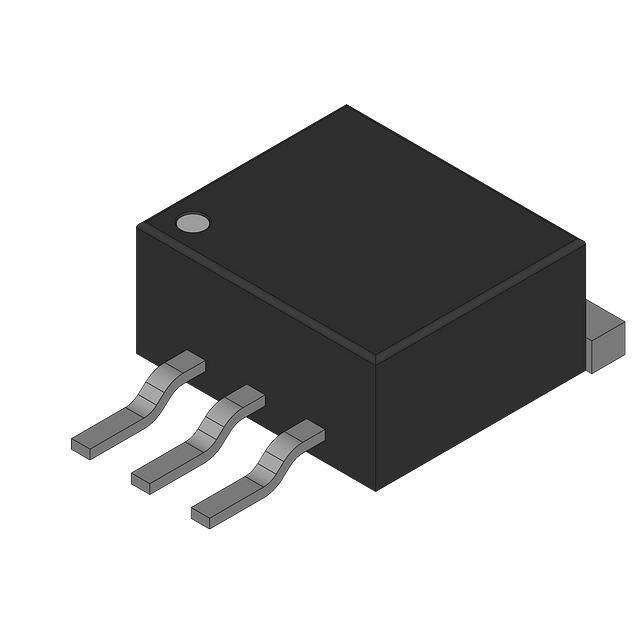
PG - TO252 - 3
14
Rev.�2.4,��2014-03-12
�IKD15N60R
TRENCHSTOPTM�RC-Series�for�hard�switching�applications
vGE(t)
90% VGE
a
a
b
b
t
iC(t)
90% IC
90% IC
10% IC
10% IC
t
vCE(t)
t
td(off)
tf
td(on)
t
tr
vGE(t)
90% VGE
10% VGE
t
iC(t)
2% IC
t
vCE(t)
2% VCE
t1
t2
t3
t4
t
15
Rev.�2.4,��2014-03-12
�IKD15N60R
TRENCHSTOPTM�RC-Series�for�hard�switching�applications
Revision�History
IKD15N60R
Revision:�2014-03-12,�Rev.�2.4
Previous Revision
Revision
Date
Subjects (major changes since last revision)
0.1
2010-02-01
-
2.1
2011-01-17
Release of final datasheet
2.2
2013-02-19
Change package
2.3
2014-02-26
Without PB free logo
2.4
2014-03-12
Storage temp -55...+150°C
We�Listen�to�Your�Comments
Any�information�within�this�document�that�you�feel�is�wrong,�unclear�or�missing�at�all�?
Your�feedback�will�help�us�to�continuously�improve�the�quality�of�this�document.
Please�send�your�proposal�(including�a�reference�to�this�document)�to:�erratum@infineon.com
Published�by
Infineon�Technologies�AG
81726�Munich,�Germany
81726�München,�Germany
©�2014�Infineon�Technologies�AG
All�Rights�Reserved.
Legal�Disclaimer
The�information�given�in�this�document�shall�in�no�event�be�regarded�as�a�guarantee�of�conditions�or�characteristics.
With�respect�to�any�examples�or�hints�given�herein,�any�typical�values�stated�herein�and/or�any�information�regarding�the
application�of�the�device,�Infineon�Technologies�hereby�disclaims�any�and�all�warranties�and�liabilities�of�any�kind,
including�without�limitation,�warranties�of�non-infringement�of�intellectual�property�rights�of�any�third�party.
Information
For�further�information�on�technology,�delivery�terms�and�conditions�and�prices,�please�contact�the�nearest�Infineon
Technologies�Office�(www.infineon.com).
Warnings
Due�to�technical�requirements,�components�may�contain�dangerous�substances.�For�information�on�the�types�in
question,�please�contact�the�nearest�Infineon�Technologies�Office.
The�Infineon�Technologies�component�described�in�this�Data�Sheet�may�be�used�in�life-support�devices�or�systems
and/or�automotive,�aviation�and�aerospace�applications�or�systems�only�with�the�express�written�approval�of�Infineon
Technologies,�if�a�failure�of�such�components�can�reasonably�be�expected�to�cause�the�failure�of�that�life-support,
automotive,�aviation�and�aerospace�device�or�system�or�to�affect�the�safety�or�effectiveness�of�that�device�or�system.�Life
support�devices�or�systems�are�intended�to�be�implanted�in�the�human�body�or�to�support�and/or�maintain�and�sustain
and/or�protect�human�life.�If�they�fail,�it�is�reasonable�to�assume�that�the�health�of�the�user�or�other�persons�may�be
endangered.
16
Rev.�2.4,��2014-03-12
�


 工商网监
湘ICP备2023018690号
工商网监
湘ICP备2023018690号
