XDPL8105 - Digital Flyback Controller IC
XDP™ digital power
Datasheet
About this document
Scope and purpose
This document contains information about Infineon high-performance single-stage digital flyback controller
XDPL8105 for LED lighting applications. Features and electrical characteristics are listed and explained.
Intended audience
This document is intended for customers wishing to design high-performance single-stage digital flyback ACDC converters for LED lighting based on the XDPL8105 controller
2016-09-28
1
Rev. 1.0
�XDPL8105 - Digital Flyback Controller IC
Datasheet
Revision History
Revision History
Page or Item
Subjects (major changes since previous revision)
Rev. 1.0, 2016-09-28
Datasheet
2
Rev. 1.0
2016-09-28
�XDPL8105 - Digital Flyback Controller IC
Datasheet
Table of Contents
About this document . . . . . . . . . . . . . . . . . . . . . . . . . . . . . . . . . . . . . . . . . . . . . . . . . . . . . . . . . . . . . . 1
Revision History . . . . . . . . . . . . . . . . . . . . . . . . . . . . . . . . . . . . . . . . . . . . . . . . . . . . . . . . . . . . . . . . . . 2
Table of Contents . . . . . . . . . . . . . . . . . . . . . . . . . . . . . . . . . . . . . . . . . . . . . . . . . . . . . . . . . . . . . . . . . 3
Overview . . . . . . . . . . . . . . . . . . . . . . . . . . . . . . . . . . . . . . . . . . . . . . . . . . . . . . . . . . . . . . . . . . . . . . . . 4
1
Pin configuration and description . . . . . . . . . . . . . . . . . . . . . . . . . . . . . . . . . . . . . . . . . . . . . . . . . . . 6
2
2.1
2.2
2.2.1
2.2.1.1
2.2.1.2
2.2.1.3
2.2.2
2.2.3
2.2.4
2.2.5
2.2.6
2.2.7
2.2.8
2.2.9
2.2.10
2.3
2.3.1
2.3.2
2.3.3
2.3.4
2.3.5
2.3.6
2.3.7
2.3.8
2.3.9
2.4
2.4.1
2.4.2
2.4.3
Functional description . . . . . . . . . . . . . . . . . . . . . . . . . . . . . . . . . . . . . . . . . . . . . . . . . . . . . . . . . . . . 7
Introduction . . . . . . . . . . . . . . . . . . . . . . . . . . . . . . . . . . . . . . . . . . . . . . . . . . . . . . . . . . . . . . . . . . . . . . . . . . . . . . 7
Controller features . . . . . . . . . . . . . . . . . . . . . . . . . . . . . . . . . . . . . . . . . . . . . . . . . . . . . . . . . . . . . . . . . . . . . . . . 7
Primary side voltage and current sensing . . . . . . . . . . . . . . . . . . . . . . . . . . . . . . . . . . . . . . . . . . . . . . . . . . 8
Input current sensing via pin CS and output current calculation . . . . . . . . . . . . . . . . . . . . . . . . . . . . 9
Input voltage sensing via pin ZCD . . . . . . . . . . . . . . . . . . . . . . . . . . . . . . . . . . . . . . . . . . . . . . . . . . . . . . . 9
Output voltage sensing via pin ZCD . . . . . . . . . . . . . . . . . . . . . . . . . . . . . . . . . . . . . . . . . . . . . . . . . . . . . 9
Primary side control scheme for output current control . . . . . . . . . . . . . . . . . . . . . . . . . . . . . . . . . . . . 10
Power factor correction (PFC) . . . . . . . . . . . . . . . . . . . . . . . . . . . . . . . . . . . . . . . . . . . . . . . . . . . . . . . . . . . . 11
Dimming via pin DIM/UART . . . . . . . . . . . . . . . . . . . . . . . . . . . . . . . . . . . . . . . . . . . . . . . . . . . . . . . . . . . . . . 11
Isolated dimming interface with CDM10V (optional) . . . . . . . . . . . . . . . . . . . . . . . . . . . . . . . . . . . . . . . . 12
Wide output load voltage range circuit (optional) . . . . . . . . . . . . . . . . . . . . . . . . . . . . . . . . . . . . . . . . . . 13
Automatic output discharge circuit (optional) . . . . . . . . . . . . . . . . . . . . . . . . . . . . . . . . . . . . . . . . . . . . . 13
VCC startup function combined with direct input monitoring . . . . . . . . . . . . . . . . . . . . . . . . . . . . . . . 13
Configurable soft start and output charging . . . . . . . . . . . . . . . . . . . . . . . . . . . . . . . . . . . . . . . . . . . . . . . 13
Configurable gate voltage rising slope at pin GD (Lower EMI) . . . . . . . . . . . . . . . . . . . . . . . . . . . . . . . . 14
Protection features . . . . . . . . . . . . . . . . . . . . . . . . . . . . . . . . . . . . . . . . . . . . . . . . . . . . . . . . . . . . . . . . . . . . . . . 15
Undervoltage lockout for VCC . . . . . . . . . . . . . . . . . . . . . . . . . . . . . . . . . . . . . . . . . . . . . . . . . . . . . . . . . . . . 16
Overvoltage protection for VCC . . . . . . . . . . . . . . . . . . . . . . . . . . . . . . . . . . . . . . . . . . . . . . . . . . . . . . . . . . 16
Over / undervoltage protection for output voltage . . . . . . . . . . . . . . . . . . . . . . . . . . . . . . . . . . . . . . . . . 16
Over / undervoltage protection for input voltage . . . . . . . . . . . . . . . . . . . . . . . . . . . . . . . . . . . . . . . . . . . 17
Input overcurrent detection level 1 (OCP1) . . . . . . . . . . . . . . . . . . . . . . . . . . . . . . . . . . . . . . . . . . . . . . . . 18
Input overcurrent protection level 2 (OCP2) . . . . . . . . . . . . . . . . . . . . . . . . . . . . . . . . . . . . . . . . . . . . . . . 18
Output overcurrent protections . . . . . . . . . . . . . . . . . . . . . . . . . . . . . . . . . . . . . . . . . . . . . . . . . . . . . . . . . . 18
Overtemperature protection . . . . . . . . . . . . . . . . . . . . . . . . . . . . . . . . . . . . . . . . . . . . . . . . . . . . . . . . . . . . . 18
Firmware protections . . . . . . . . . . . . . . . . . . . . . . . . . . . . . . . . . . . . . . . . . . . . . . . . . . . . . . . . . . . . . . . . . . . 19
Configuration and support . . . . . . . . . . . . . . . . . . . . . . . . . . . . . . . . . . . . . . . . . . . . . . . . . . . . . . . . . . . . . . . . 20
Configuration procedure and design-in support . . . . . . . . . . . . . . . . . . . . . . . . . . . . . . . . . . . . . . . . . . . 20
Overview configurable parameters and functions . . . . . . . . . . . . . . . . . . . . . . . . . . . . . . . . . . . . . . . . . . 20
Debug mode support . . . . . . . . . . . . . . . . . . . . . . . . . . . . . . . . . . . . . . . . . . . . . . . . . . . . . . . . . . . . . . . . . . . . 25
3
3.1
3.2
3.3
3.4
Electrical Characteristics . . . . . . . . . . . . . . . . . . . . . . . . . . . . . . . . . . . . . . . . . . . . . . . . . . . . . . . . .
Package Characteristics . . . . . . . . . . . . . . . . . . . . . . . . . . . . . . . . . . . . . . . . . . . . . . . . . . . . . . . . . . . . . . . . . . .
Absolute Maximum Ratings . . . . . . . . . . . . . . . . . . . . . . . . . . . . . . . . . . . . . . . . . . . . . . . . . . . . . . . . . . . . . . . .
Operating Conditions . . . . . . . . . . . . . . . . . . . . . . . . . . . . . . . . . . . . . . . . . . . . . . . . . . . . . . . . . . . . . . . . . . . . .
DC Electrical Characteristics . . . . . . . . . . . . . . . . . . . . . . . . . . . . . . . . . . . . . . . . . . . . . . . . . . . . . . . . . . . . . . .
4
Outline dimensions . . . . . . . . . . . . . . . . . . . . . . . . . . . . . . . . . . . . . . . . . . . . . . . . . . . . . . . . . . . . . . 32
Datasheet
3
26
26
26
27
28
Rev. 1.0
2016-09-28
�XDPL8105 - Digital Flyback Controller IC
Datasheet
Overview
Product highlights
•
Highly accurate primary side controlled output current (Line/load regulation typical within +/- 3%)
•
High power quality (typical PF up to 0.99 and THD < 10%)
•
High Efficiency (up to 91%)
•
Configurable output current with no BOM change
•
Supports universal input voltage (85 – 305 V AC)
•
Supports wide output load voltage (up to 4 times of minimum output load voltage)
•
Ideal for application with dimming signal from micro-controller on primary side
•
Supports fully isolated 0 – 10 V dimming with Infineon CDM10V
•
Supports low output current dimming.
•
Low standby power
Features
•
Single stage QR Flyback with PFC and high precision primary side controlled constant current output
•
Excellent line and load regulation
•
Supports AC input (45 ~ 65 Hz) and/or DC input voltage operation
•
Integrated 600 V startup cell
•
Low Bill Of Material (BOM)
•
Configurable parameters, e.g. adjustable voltage and current ranges, protection modes
•
Supports non-dimmed and/or dimmed applications.
•
Intelligent thermal management with adaptive thermal protection
Applications
•
Electronic control gear for LED luminaires (5 W to 80 W)
Description
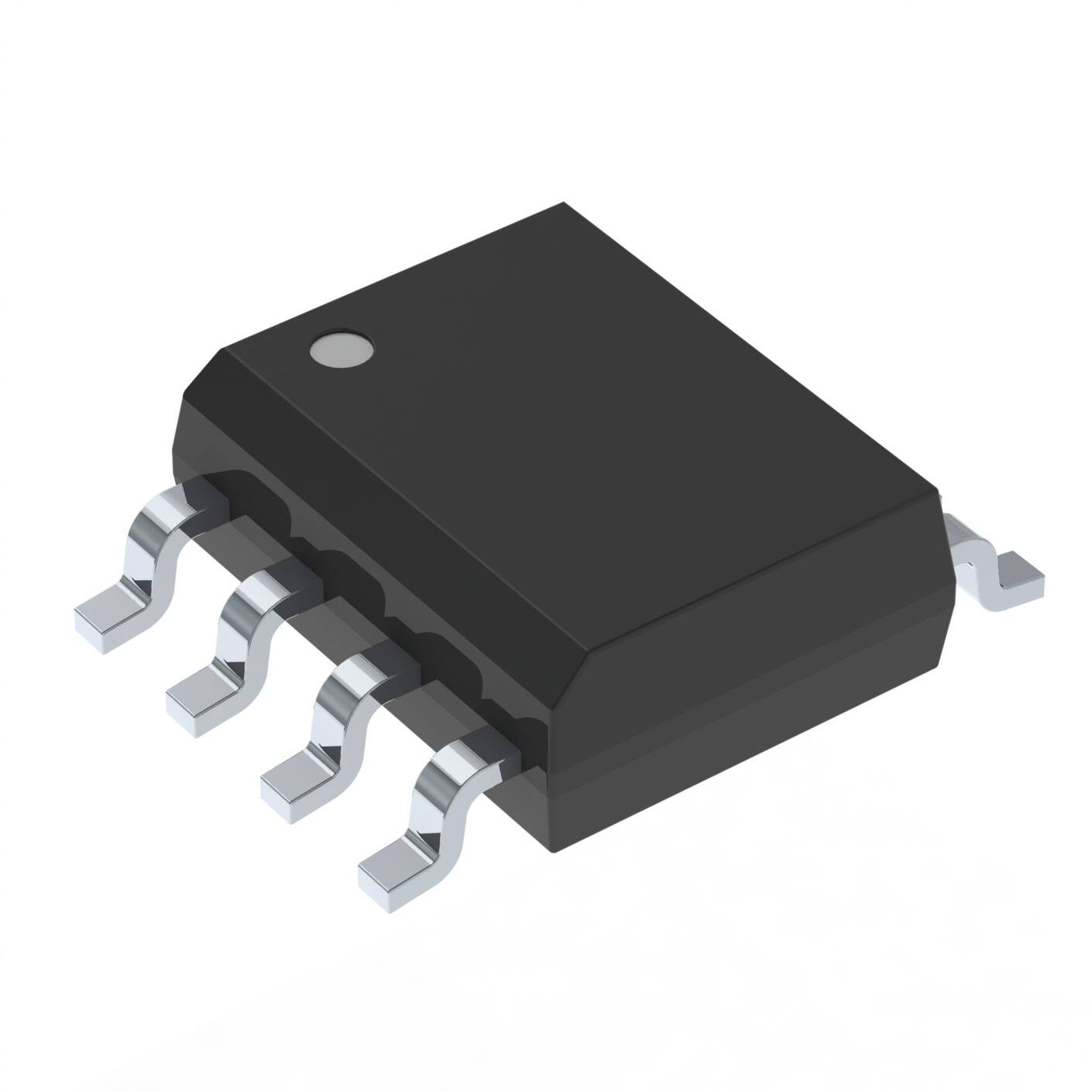
The XDPL8105 is a high performance microcontroller-based digital single-stage flyback controller with power
factor correction (PFC) for constant output current applications. The IC is available in a DSO-8 package and
supports a wide feature set, requiring a minimum of external components. The digital engine offers the
possibility to configure operational parameters and protection modes, which helps to ease the design phase
and allows a reduced number of hardware variants in production. Accurate primary side output current
control is implemented to eliminate the need for secondary side feedback circuitry.
Table 1
Product Type
Package
XDPL8105
PG-DSO-8
Datasheet
4
Rev. 1.0
2016-09-28
�XDPL8105 - Digital Flyback Controller IC
Datasheet
85 … 305 Vac
Output
External Vcc supply
VCC
Internal
temperature
sensor
Zero crossing
detection
Startup cell
control
XDPL8105
PWM
Square wave
generator
Dimming /
UART
Current
sensing
HV
SQW
DIM/UART
ZCD
GD
CS
GND
PWM
Dimming
signal
Primary side
Micro-controller
RC Low
Pass Filter
Parameters
Configuration
Figure 1
Typical application 1 (Primary side micro-controller dimming)
85 … 305 Vac
Output
VCC
Internal
temperature
sensor
Zero crossing
detection
Startup cell
control
XDPL8105
PWM
Square wave
generator
Dimming /
UART
Current
sensing
HV
SQW
DIM/UART
ZCD
GD
CS
Isolated Dimming
Circuit with CDM10V
Vcc
GND
Iout
Digital to
Analog
conversion
CDM10V
Rdim+
0 – 10 V
input
Parameters
Configuration
Figure 2
Datasheet
Typical application 2 (Secondary side 0-10V dimming)
5
Rev. 1.0
2016-09-28
�XDPL8105 - Digital Flyback Controller IC
Datasheet
Pin configuration and description
1
Pin configuration and description
The pin configuration is shown in Figure 3. The pin functions are listed and described in Table 2.
ZCD
1
8
GND
DIM/UART
2
7
VCC
CS
3
6
SQW
GD
4
5
HV
PG-DSO-8 (150mil)
Figure 3
Pin configuration
Table 2
Pin definitions and functions
Symbol
Pin
Type Function
ZCD
1
I
Zero crossing detection
Pin ZCD is connected to an auxiliary winding via the resistor divider for zero
crossing detection. Output & input voltage are also measured with the
sampled positive & negative voltage sensing.
DIM/UART
2
I/O
Dimming / UART
Shared functioning pin with either as dimming Input or UART configuration.
The dimming input voltage, VDIM sensing range is from 0.1 to 2V. Once the pin
voltage exceeds 2.2V (for example when the isolated USB interface board is
connected to the IC), this pin will function as UART configuration and the IC
will stay in non-dimming operation unless it is reset or restarted.
CS
3
I
Current sense
Pin CS is connected to an external shunt resistor and the source of the power
MOSFET.
GD
4
O
Gate driver
Output signal to drive an external power MOSFET.
HV
5
I
High voltage
Pin HV is connected to the rectified input voltage via external resistor. An
internal 600 V HV startup-cell is used to pre-charge VCC for IC startup once the
mains input voltage is applied. Furthermore sampled high voltage sensing is
used for synchronization with the input voltage frequency.
SQW
6
O
Square wave generator
Pin SQW is capable of providing a square wave signal for driving the isolated
dimming transformer circuit, if necessary. Otherwise, this signal can be
turned off by parameter configuration.
VCC
7
I
Voltage supply
IC power supply
GND
8
—
Power and signal ground
Datasheet
6
Rev. 1.0
2016-09-28
�XDPL8105 - Digital Flyback Controller IC
Datasheet
Functional description
2
Functional description
The functional description provides an overview about the integrated functions and features as well as their
relationship. The mentioned parameters and equations are based on typical values at TA = 25 °C. The
corresponding min. and max. values are shown in the electrical characteristics.
2.1
Introduction
The XDPL8105 is a digital AC/DC flyback controller with Power Factor Correction (PFC). The PFC function
enables a rectified sinusoidal input current waveform with a power factor typically up to 0.99 and THD < 10%
for a wide range of operating conditions. XDPL8105 provides primary side constant output current control that
avoids the secondary side control feedback loop circuitry usually needed in isolated power converters. This
approach supports a low part count that is necessary to build up the application. XDPL8105 has multi-mode
operations and it selects the best mode of operation based on operating conditions. The multi-mode
operation will automatically switch between quasi-resonant mode (QRM) and discontinuous mode (DCM) and
active burst mode (ABM). In addition, XDPL8105 supports both secondary side 0 - 10 V dimming and primary
side micro-controller dimming application. Digital and RF interfaces can be supported by a microcontroller
using a digital-to-analog converter.
The XDPL8105 provides a high flexibility in the design-in of the application. A graphic user interface (GUI) tool
called .dp Vision supports users to tune a set of configurable parameters. The configuration can be done via a
single pin UART interface at pin DIM/UART.
2.2
Controller features
Table 3 gives an overview about the controller features that are described in the mentioned chapters.
Table 3
Controller features
Primary side voltage and current sensing
Chapter 2.2.1
Primary side control scheme for output current control
Chapter 2.2.2
Power factor correction (PFC)
Chapter 2.2.3
Dimming via pin DIM/UART
Chapter 2.2.4
Isolated dimming interface with CDM10V (optional)
Chapter 2.2.5
Wide output load voltage range circuit (optional)
Chapter 2.2.6
Automatic output discharge circuit (optional)
Chapter 2.2.7
VCC startup function combined with direct input monitoring
Chapter 2.2.8
Configurable soft start and output charging
Chapter 2.2.9
Configurable gate voltage rising slope at pin GD (Lower EMI)
Chapter 2.2.10
Datasheet
7
Rev. 1.0
2016-09-28
�XDPL8105 - Digital Flyback Controller IC
Datasheet
Functional description
2.2.1
Primary side voltage and current sensing
The XDPL8105 provides a primary side control of the output current by means of measuring the input peak
current and measuring the conduction period of the output diode. Input and output voltages are measured at
pin ZCD using an external resistor divider and an auxiliary winding of the transformer. The voltage signal VAUX
contains the information of the rectified input voltage Vin and the output voltage Vout at the secondary side.
Figure 4 shows typical current and voltage waveforms of the Quasi-Resonant flyback application.
The following topics are described:
•
Input current sensing via pin CS and output current calculation (Chapter 2.2.1.1)
•
Input voltage sensing via pin ZCD (Chapter 2.2.1.2)
•
Output voltage sensing via pin ZCD (Chapter 2.2.1.3)
VAUX
V AUX = VOut ×
N_a
N_s
Zero crossing detection
0V
V AUX = −Vin ×
N _a
N_p
`
Valley switching
Ip
t
tsample1
ITrafo
tsample2
Is
+
+
Vin
Vout
-
-
N_p
N_a
Tperiod
N_s
+
Is(pk)
VAUX
Ip(pk)
Ip
Is
Ip
t
tdemag
VGD
ton
t
Figure 4
Datasheet
Typical waveforms (Example with QRM valley switching)
8
Rev. 1.0
2016-09-28
�XDPL8105 - Digital Flyback Controller IC
Datasheet
Functional description
2.2.1.1
Input current sensing via pin CS and output current calculation
The output current Iout is determined by the primary input peak current Ip,pk which is sensed at pin CS at time
tsample1, by the duration of conduction of the output diode (tsample2 - tsample1) and by the switching period tperiod.
The result is used for the control loop and for output overcurrent protections (Chapter 2.3.7).
2.2.1.2
Input voltage sensing via pin ZCD
The input voltage is measured using current IIV at pin ZCD at time tsample1. As the voltage VAUX is a negative
voltage, pin ZCD is clamped to a fixed negative voltage VINPCLN (Figure 5). The negative current IIV (flowing out
of pin ZCD) is proportional to the input voltage. The monitored input voltage is used for input over- and
undervoltage protection (Chapter 2.3.4).
N_a N_p
R_ZCD_1
ZCD
VIN
Input
filter cap
IIV
VAUX
VINPCLN
Figure 5
2.2.1.3
GD
R_ZCD_2
Input voltage sensing via pin ZCD
Output voltage sensing via pin ZCD
The output voltage is measured using voltage VZCDSH at pin ZCD at time tsample2 (Figure 6). The measured
voltage at pin ZCD and the dimensioning of the resistor divider are used to calculate the reflected output
voltage at the auxiliary winding. The sensed output voltage is used for output over- and undervoltage
protection (Chapter 2.3.3). The relation between VCC and ZCD can be decoupled by adding a voltage
regulator for VCC (Chapter 2.2.6).
V _out_diode_drop
N _a
R _ZCD_1
N _s
V Out
ZCD
V AUX
R _ZCD_2
V ZCDSH
Figure 6
Output voltage sensing via pin ZCD
Note: Please note that the time (tsample2 - tsample1) has to be longer than 2.0 µs to ensure that the reflected output
voltage can be correctly sensed at pin ZCD!
Datasheet
9
Rev. 1.0
2016-09-28
�XDPL8105 - Digital Flyback Controller IC
Datasheet
Functional description
2.2.2
Primary side control scheme for output current control
The basic control scheme for the primary side constant current control is shown in Figure 7.
R_ZCD_1
ZCD
Zero crossing
detection
R_ZCD_2
N_a
Output current
calculation
CS
N_p
Moving
average filter
Peak input
current detection
-
PI
GD
min
Intelligent
thermal
management
R_CS
VIN
Dimming
curve
DIM/
UART
Figure 7
PWM
+
Integrated PI control scheme for output current control
The sampled signal VCS at pin CS and zero crossing detection at pin ZCD are used to estimate the output
current Iout as described in Chapter 2.2.1.1. The internal reference current I_out_set is weighted according to
thermal management and dimming curve. The average estimated output current is compared with the
weighted reference current to generate an error signal. The error signal is fed into a PI regulator to control the
PWM at pin GD for the power MOSFET. The coefficients of the PI regulator are configurable.
The PI regulator allows different modes of operation as shown in Figure 8:
•
Quasi-resonant mode (QRM)
This mode controls the on-time and maximizes the efficiency by switching on at the 1st valley of the VAUX
signal. This ensures zero-current switching with a minimum of switching losses.
•
Discontinuous mode (DCM)
This mode is used if the on-time cannot be reduced further in QRM while the output is being dimmed. The
controller will extend the switching period later than the 1st valley to control the output power.
•
Active-Burst mode (ABM)
To extend the dimming range even further, XDPL8105 features an ABM which is automatically aligned with
the input frequency to avoid any undesired effects like flicker or shimmer as well as to reduce any audible
noise.
The controller will autonomously select the best mode of operation based on operation conditions like input
voltage, input frequency and dimming input voltage which defines the output power.
Datasheet
10
Rev. 1.0
2016-09-28
�XDPL8105 - Digital Flyback Controller IC
Datasheet
Functional description
Power
t_on_max
On-time controlled
t_on_min
QRM
f_sw_max or QR switching frequency (with t_on_min)
Frequency controlled
DCM
f_sw_min_DCM
ABM
Figure 8
Pulse number controlled
Overview of operation modes
2.2.3
Power factor correction (PFC)
The gate driver GD is used for driving the power MOSFET of the flyback. Constant output current regulation
and a sinusoidally shaped input current are achieved by on-time control. The quasi-constant on-time ton
ensures high PF and low THD performance. The internal control signal ton is calculated by the digital engine so
that the output current is close to the target current (Chapter 2.2.2).
Optionally, an enhanced PFC (EPFC) scheme can be enabled to compensate the input current distortion
caused by the EMI filter1). In this scheme, the on-time is a function of the internal controller signal ton, the input
voltage Vin, output voltage Vout, output current Iout, phase angle and a configurable gain parameter (C_EMI)
optimizing the input current waveform (Chapter 2.4).
2.2.4
Dimming via pin DIM/UART
The voltage sensed at pin DIM/UART is used to determine the output current level. Figure 9 shows the relation
of DIM/UART voltage to the output current target value. Levels of V_DIM_min and V_DIM_max2) ensure that
minimum current I_out_dim_min and maximum current I_out_set can always be achieved, making the application
robust against dimmer and other component tolerances. The sampled voltage VDIM at pin DIM/UART is digitally
filtered to stabilize light output. The XDPL8105 can also be configured to use a linear or a quadratic dimming
curve.
Iout
Iout
I_out_set
I_out_set
Figure 9
VDIM/UART
I_out_dim_min
V_DIM_max
2.0V
V_DIM_min
V_DIM_max
V_DIM_min
I_out_dim_min
2.0V
VDIM/UART
Dimming curves based on pin DIM/UART voltage
1) Patent pending
2) fixed at 1.72V
Datasheet
11
Rev. 1.0
2016-09-28
�XDPL8105 - Digital Flyback Controller IC
Datasheet
Functional description
Optionally, the dim-to-off feature can be enabled by parameter EN_DIM_TO_OFF, so that the output current can
be turned off and on with DIM/UART pin voltage of V_DIM_off and V_DIM_on respectively.
Iout
Iout
I_out_set
I_out_set
Figure 10
I_out_dim_min
V_DIM_max
2.0V
VDIM/UART
V_DIM_off
V_DIM_on
V_DIM_min
V_DIM_max
V_DIM_off
V_DIM_on
V_DIM_min
I_out_dim_min
2.0V
VDIM/UART
Dimming curves based on pin DIM/UART voltage (with dim-to-off feature enabled)
Note: The dim-to-off feature requires an active voltage source to exit the dim-to-off state.
In some cases where the dimming control circuitry is on the primary side and it is using PWM control, please
use the RC low pass filter circuit which will convert the PWM dimming signal to an analog dimming voltage for
measurement on pin DIM/UART.
2.2.5
Isolated dimming interface with CDM10V (optional)
Figure 11 shows an exemplary schematic of a 0-10V dimming interface for low BOM cost, using CDM10V by
Infineon. CDM10V is a fully integrated 0-10V dimming interface IC which transmits secondary side analog
voltage based signals from 0-10V dimmer to primary side, by driving an external opto-coupler with a 5mA
current based PWM signal. The secondary auxiliary winding is necessary to supply the operating voltage of
CDM10V. For more details about CDM10V, please visit Infineon website: http://www.infineon.com/cdm10v
Figure 11
Datasheet
Optional circuit for isolated dimming with CDM10V
12
Rev. 1.0
2016-09-28
�XDPL8105 - Digital Flyback Controller IC
Datasheet
Functional description
2.2.6
Wide output load voltage range circuit (optional)
If wide output load voltage is required, a regulator for VCC is required. This regulator limits the maximum
voltage at pin VCC during steady state operation. Figure 12 shows an exemplary schematic for the optional
wide output voltage range support. A wide output voltage range impacts efficiency due to the necessary
voltage regulator for VCC.
RVCCreg
CVCCreg
ZDVCCreg
VCC
CVCC
GND
Figure 12
2.2.7
Optional wide output voltage range circuit
Automatic output discharge circuit (optional)
In case of a fault (e.g. Open Load) the output capacitors stay charged and may keep a high voltage. It is
therefore recommended to add an automatic output discharge circuit. This circuit discharges the output
capacitors if the main switch stops switching. For the circuit design, please refer the schematic in the
application note of the XDPL8105 40W reference design with CDM10V.
2.2.8
VCC startup function combined with direct input monitoring
There are two main functions supported at pin HV which needs to be connected to the input voltage via
resistor and two diodes.
The integrated HV startup-cell is switched on during the VCC startup phase before the IC is activated. Current
flows from pin HV to pin VCC via an internal diode, which charges the capacitor at pin VCC. Once the voltage
at pin VCC exceeds the VVCCon threshold, the IC enables the active operating phase and switches off the HV
startup-cell.
Furthermore, a direct input monitoring is supported that is controlled by an internal timer. The timer switches
on the HV startup cell for a very short time after a defined period. During this short on-time the current is
sensed at pin HV by a comparator to synchronize to frequency and phase of the input voltage.
2.2.9
Configurable soft start and output charging
After startup condition(e.g. input voltage, junction temperature) is checked within the limits, the IC initiates a
soft-start. During soft-start, the switching stress for the power MOSFET, diode and transformer is minimized.
The cycle-by-cycle current limit is increased in steps with a configurable time t_ss for each step. The number of
soft start steps is defined by parameter n_ss1). After startup pin CS maximum voltage limit of V_start_OCP1 level
has been reached, the output will be charged up with maximum on-time and V_start_OCP1 level to the minimum
output voltage that ensures self-supply, V_out_start but below the fully dimmed minimum output LED voltage,
V_out_dim_min. After the output voltage reaches V_out_start level, the output constant current control loop
1) fixed at 3
Datasheet
13
Rev. 1.0
2016-09-28
�XDPL8105 - Digital Flyback Controller IC
Datasheet
Functional description
(Chapter 2.2.2) takes over and the pin CS maximum voltage limit will be changed from V_start_OCP1 to V_OCP1
level.
Voltage
Startup
Output charging
phase
Soft start phase
Output current
Regulated Mode
Vout
V_out_dim_min
V_out_start
Control loop
initialization
CS pin max voltage limit
V_OCP1
V_start_OCP1
Startup Check
(e.g. input voltage,
IC temperature)
0
Figure 13
2.2.10
tSS
2 tSS
3 tSS
tout,charge
time
Configurable soft start and output charging phase
Configurable gate voltage rising slope at pin GD (Lower EMI)
The gate driver output signal can be configured with respect to the rising slope for switching on the power
MOSFET. This feature can save BOM components (1 diode & 1 resistor) which are conventionally added to
achieve the same purpose for EMI improvement. The maximum gate drive current I_GD_pk for the gate driver
slope can be set between 30 mA and 118 mA (Chapter 2.4). Figure 14 shows the gate driver output signal.
V GD
10.5V
I _GD_pk
=118m A
I _GD_pk
= 30m A
t
Figure 14
Datasheet
Configurable gate voltage rising slope for lower EMI
14
Rev. 1.0
2016-09-28
�XDPL8105 - Digital Flyback Controller IC
Datasheet
Functional description
2.3
Protection features
Table 4 gives an overview about the available protection features and corresponding default actions in case
a protection feature is triggered. Two protection reactions (auto restart mode and latch mode) are
implemented.
Auto restart mode
Once the auto restart mode is activated, the IC stops the power MOSFET switching at pin GD and reduces the
current consumption to a minimum. After the configurable auto restart time t_auto_restart the IC initiates a new
start-up1). During this auto restart, the HV startup-cell is switched on and off in order to keep the VCC between
VUVLO and VOVLO thresholds2). The auto restart cycle starts first with charging the VCC capacitor by means of
switching on the HV startup cell until the VVCCon threshold is exceeded. A regular startup procedure with soft
start is initiated afterwards.
Latch mode
When latch mode is activated, the power MOSFET switching at pin GD is immediately stopped. The HV startupcell is switched on and off in order to keep the VCC between VUVLO and VOVLO thresholds. The device stays in this
state until input voltage is completely removed and the VCC voltage drops below the VUVLO threshold. The IC
can then be re-started by applying input voltage.
Table 4
Protection Features
Protection Feature
Active Period
(if enabled)
Reaction
Description
Undervoltage lockout for VCC
Always on
Hardware restart
1)
Chapter 2.3.1
Overvoltage protection for VCC
Always on
Latch mode
Chapter 2.3.2
Overvoltage protection for Vout
Always on
Auto restart1)
Chapter 2.3.3
Auto restart
Chapter 2.3.3
Startup Undervoltage protection for Vout During startup
Auto restart
Chapter 2.3.3
Overvoltage protection for Vin
Always on
2)
Latch mode
Chapter 2.3.4
Undervoltage protection for Vin
Always on
2)
Auto restart
Chapter 2.3.4
Input overcurrent detection level 1
Always on
Current limiting
Chapter 2.3.5
Input overcurrent protection level 2
Always on
Undervoltage protection for Vout
Activated after startup
2)
Latch mode
Chapter 2.3.6
Output current protection (average)
2)
Activated after startup
Auto restart
Chapter 2.3.7
Output current protection (peak)
Activated after startup2)
Auto restart
Chapter 2.3.7
Overtemperature protection
Always on
Latch mode
Chapter 2.3.8
Firmware protections
(1st Watchdog & RAM Parity)
Always on
Auto restart
Chapter 2.3.9
1) Protection which its reaction can be configured to either auto restart mode or latch mode.
2) Protection which can be disabled or enabled by configuration.
1) After t_auto_restart, the VCC will be charged to VVCCon again(see Chapter 2.2.8). Therefore, the effective auto-restart time is longer
than t_auto_restart
2) This feature can be disabled for applications with externally supplied VCC.
Datasheet
15
Rev. 1.0
2016-09-28
�XDPL8105 - Digital Flyback Controller IC
Datasheet
Functional description
2.3.1
Undervoltage lockout for VCC
An undervoltage lockout unit (UVLO) is implemented which ensures a defined enabling and disabling of the IC
operation depending on the supply voltage at pin VCC. The UVLO contains a hysteresis with the voltage
thresholds VVCCon for enabling the IC and VUVOFF for disabling the IC. Once the mains input voltage is applied,
current flows through an external resistor into pin HV via the integrated diode to pin VCC. The IC is enabled
once VCC exceeds the threshold VVCCon and enters normal operation if no fault condition is detected. In this
phase VCC will drop until the self supply via the auxiliary winding takes over the supply at pin VCC. For proper
startup, the output voltage of V_out_start level for Vcc self supply via auxiliary winding must be in place before
VCC falls below VUVOFF threshold and before timeout of t_start_max for the startup output undervoltage
detectionoccurs (See Chapter 2.3.3)
2.3.2
Overvoltage protection for VCC
Overvoltage detection at pin VCC is implemented via a threshold of V_VCC_max.
2.3.3
Over / undervoltage protection for output voltage
Overvoltage (e.g. Open Load) or undervoltage (e.g. Output short) detection of the output voltage Vout is
provided by the measurement and calculation as described in Chapter 2.2.1.3. The overvoltage protection
reaction (auto-restart or latch) and detection thresholds V_outOV are configurable. For output overvoltage
protection in auto-restart reaction, either slow or fast auto-restart can also be selected.
Please note that there are possibilities where critical protection like output over-voltage not working properly
(example: wrong parameter configurations loaded). Thus, please consider adding zener diode or any voltage
suppressor device/circuit on output for reinforced safety purpose.
Note: It is mandatory to have output discharge resistor/circuit which discharges the output capacitor after
triggering open load protection at V_outOV. Latch reaction is recommended for open load protection as
it can shut down the unit to prevent output overcharged if the discharge resistor ohmic value is too high.
Vout
With fast auto‐restart enabled and
with output dummy resistor (passive)
Triggering of output OVP
V_outOV
With slow auto‐restart and with
output dummy resistor (passive)
Removal of LED load (output open)
With slow auto‐restart and with
output discharge circuit (active)
V_out_dim_min
V_out_start
Start of control-loop
Turn-on
time
Startup
Figure 15
Datasheet
Regulated Mode
Auto-restart
protection
Voltage threshold for output overvoltage protection
16
Rev. 1.0
2016-09-28
�XDPL8105 - Digital Flyback Controller IC
Datasheet
Functional description
The undervoltage protection reaction is fixed as auto-restart and its detection threshold V_outUV is fixed at 50%
of the configurable fully dimmed minimum output load voltage parameter, V_out_dim_min. Output undervoltage
protection is disabled during the startup phase.
Vout
Output short
V_out_dim_min
V_out_start
V_outUV
Start of control-loop
Output UVP
triggered after
t_Vout_blank
Turn-on
time
Startup
Figure 16
Regulated Mode
Voltage threshold for output undervoltage protection
In case of output short/undervoltage, the auxiliary winding cannot provide power to VCC during startup
because the output voltage stays below V_out_start or V_outUV. Therefore, the startup output undervoltage
protection is triggered if the output voltage has not reached V_out_start before a configurable timeout of
t_start_max occurs during the startup phase. To ensure that the startup undervoltage protection is in autorestart reaction, the pin VCC capacitance has to be high enough to maintain the VCC above VUVOFF threshold
long enough until the timeout of t_start_max occurs during the startup phase.
Vout
V_out_dim_min
V_out_start
V_outUV
Startup Output
UVP triggered
Turn-on
time
t_start_max
Figure 17
2.3.4
Voltage and timing threshold for startup output undervoltage protection
Over / undervoltage protection for input voltage
An over / undervoltage detection of the input voltage Vin is provided by the measurement and calculation as
described in Chapter 2.2.1.2. The Vin rms value is calculated based on the measured Vin peak value and
compared to the configurable internal input over / undervoltage protection thresholds V_inOV and V_inUV
(Chapter 2.4).
Datasheet
17
Rev. 1.0
2016-09-28
�XDPL8105 - Digital Flyback Controller IC
Datasheet
Functional description
Figure 18 shows an exemplary setting of both over- and undervoltage thresholds together with configurable
startup thresholds V_in_start_min and V_in_start_max to create hysteresis for flicker-free operation at auto-restart.
V in
Shut-off
V_inOV
V_in_start_max
Turn-on
Turn-on
Turn-on
V_in_start_min (Brown-in level)
V_inUV (Brown-out protection level)
Shut-off
t
Figure 18
2.3.5
Voltage threshold for input over / undervoltage protection
Input overcurrent detection level 1 (OCP1)
The input overcurrent protection level 1 is performed by means of the cycle-by-cycle peak current limitation
to V_OCP1. A leading edge blanking, t_CSLEB prevents the IC from falsely switching off the power MOSFET due to
a leading edge spike.
2.3.6
Input overcurrent protection level 2 (OCP2)
The input overcurrent protection level 2 is meant for covering fault conditions like a short in the transformer
primary winding. In this case overcurrent protection level 1 will not limit properly the peak current due to the
very steep slope of the peak current. Once the threshold V_OCP2 is exceeded for longer than t_CSOCP2, the
protection is triggered.
2.3.7
Output overcurrent protections
The XDPL8105 includes protections against exceeding an average and peak current limit. The average output
current is calculated over one half cycle of the input frequency to remove the output current ripple. With autorestart reaction, either slow auto-restart or fast auto-restart can be selected.
2.3.8
Overtemperature protection
XDPL8105 offers a conventional as well as an adaptive overtemperature protection scheme using an internal
temperature sensor.
Note: Please note that the internal temperature sensor may not be able to sense and protect the temperature
of external components (e.g. power MOSFET, VCC regulator) without sufficient thermal coupling.
Conventional overtemperature protection
The overtemperature protection initiates a thermal shutdown once the internal temperature detection level
T_critical is reached. With latch mode protection, IC will turn off and only restart after recycling of input power.
At startup, junction temperature has to be below T_start.
Datasheet
18
Rev. 1.0
2016-09-28
�XDPL8105 - Digital Flyback Controller IC
Datasheet
Functional description
Iout
Latch Reset
T_start
Or below
Figure 19
T_critical
TJ
Conventional temperature protection
Adaptive temperature protection
To protect load and driver against overtemperature, XDPL8105 features a reduction of output current below
maximum current I_out_set. As long as temperature T_hot is exceeded, the current is gradually reduced as shown
in Figure 20. If a reduction down to a minimum current I_out_red is not able to compensate the increase of
temperature, the overtemperature protection (with latch mode) is entered when T_critical is reached.
Iout
Iout
I_out_red … I _out_set
I_out_red … I _out_set
t_step
I_out_step
I _out_red
I _out_red
TJ = T_hot T_hot


 工商网监
湘ICP备2023018690号
工商网监
湘ICP备2023018690号
