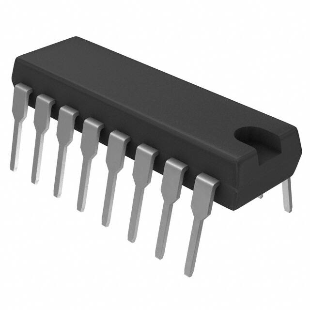
HCF4076B
4 BIT D TYPE REGISTERS
■
■
■
■
■
■
■
■
■
THREE STATE OUTPUTS
INPUT DISABLE WITHOUT GATING THE
CLOCK
GATED OUTPUT CONTROL LINES FOR
ENABLING OR DISABLING THE OUTPUTS
BUFFERED INPUTS AND OUTPUTS
QUIESCENT CURRENT SPECIFIED UP TO
20V
5V, 10V AND 15V PARAMETRIC RATINGS
INPUT LEAKAGE CURRENT
II = 100nA (MAX) AT VDD = 18V TA = 25°C
100% TESTED FOR QUIESCENT CURRENT
MEETS ALL REQUIREMENTS OF JEDEC
JESD13B "STANDARD SPECIFICATIONS
FOR DESCRIPTION OF B SERIES CMOS
DEVICES"
DESCRIPTION
HCF4076B is a monolithic integrated circuit
fabricated in Metal Oxide Semiconductor
technology available in DIP and SOP packages.
HCF4076B is a four bit register consisting of
D-TYPE flip-flops that feature three state outputs.
Data Disable inputs are provided to control the
entry of data into the flip-flops. When both Data
)
s
(
ct
DIP
SOP
ORDER CODES
PACKAGE
TUBE
DIP
SOP
HCF4076BEY
HCF4076BM1
)
s
t(
T&R
c
u
d
HCF4076M013TR
o
r
P
Disable inputs are low, data at the D inputs are
loaded into their respective flip-flops on the next
positive transition of the clock input. Output
Disable inputs are also provided. When the Output
Disable inputs are both low, the normal logic
states of the four outputs are available to the load.
The outputs are disabled independently of the
clock by a high logic level at either Output Disable
input, and present a high impedance.
e
t
le
o
s
b
O
-
u
d
o
r
P
e
t
e
l
o
PIN CONNECTION
s
b
O
September 2002
1/9
�HCF4076B
IINPUT EQUIVALENT CIRCUIT
PIN DESCRIPTION
PIN No
SYMBOL
14, 13, 12,
11
DATA1 to
DATA 4
10, 9
G1, G2
1, 2
7
15
8
M, N
CLOCK
RESET
VSS
16
VDD
NAME AND FUNCTION
D Inputs
Data Input Disable
Control
Output Disable Control
Clock Input
Reset Input
Negative Supply Voltage
Positive Supply Voltage
TRUTH TABLE
DATA INPUT DISABLE
DATA D
NEXT STATE
OUTPUT
X
X
X
X
L
Q
H
X
X
L
X
H
X
L
L
L
L
L
L
X
X
RESET
CLOCK
G1
G2
X
X
L
H
L
L
X
L
H
L
X
b
O
-
so
X
e
t
le
o
r
P
c
u
d
Q
Q
)
s
t(
NO CHANGE
NO CHANGE
NO CHANGE
H
H
L
L
X
Q
NO CHANGE
X
Q
NO CHANGE
X : Don’t Care
When either Output Disable M or N is high, the outputs are disabled (high impedance state) : however sequential operation of the flip-flop is
not affected.
)
s
(
ct
FUNCTIONAL DIAGRAM
u
d
o
r
P
e
t
e
l
o
s
b
O
2/9
�HCF4076B
LOGIC DIAGRAM
c
u
d
e
t
le
ABSOLUTE MAXIMUM RATINGS
Symbol
VDD
Parameter
(s)
Supply Voltage
VI
DC Input Voltage
II
DC Input Current
t
c
u
d
o
r
P
e
Top
Power Dissipation per Package
Power Dissipation per Output Transistor
Operating Temperature
Tstg
Storage Temperature
PD
t
e
l
o
o
s
b
O
-
)
s
t(
o
r
P
Value
Unit
-0.5 to +22
V
-0.5 to VDD + 0.5
V
± 10
mA
200
100
mW
mW
-55 to +125
°C
-65 to +150
°C
Absolute Maximum Ratings are those values beyond which damage to the device may occur. Functional operation under these conditions is
not implied.
All voltage values are referred to VSS pin voltage.
s
b
O
RECOMMENDED OPERATING CONDITIONS
Symbol
VDD
Parameter
Supply Voltage
VI
Input Voltage
Top
Operating Temperature
Value
Unit
3 to 20
V
0 to VDD
V
-55 to 125
°C
3/9
�HCF4076B
DC SPECIFICATIONS
Test Condition
Symbol
IL
Parameter
Quiescent Current
High Level Output
Voltage
VOH
Low Level Output
Voltage
VOL
0/5
0/10
0/15
0/20
0/5
0/10
0/15
5/0
10/0
15/0
High Level Input
Voltage
VIH
Low Level Input
Voltage
VIL
Output Drive
Current
IOH
Output Sink
Current
IOL
Input Leakage
Current
3-State Output
Current
Input Capacitance
II
IOZ
CI
VO
(V)
VI
(V)
0/5
0/5
0/10
0/15
0/5
0/10
0/15
0.5/4.5
1/9
1.5/13.5
4.5/0.5
9/1
13.5/1.5
2.5
4.6
9.5
13.5
0.4
0.5
1.5
0/18
o
r
P
e
|IO| VDD
(µA) (V)
很抱歉,暂时无法提供与“HCF4076BEY”相匹配的价格&库存,您可以联系我们找货
免费人工找货