VNQ7E100AJ
Datasheet
Quad channel high-side driver with CurrentSense analog feedback for automotive
applications
Features
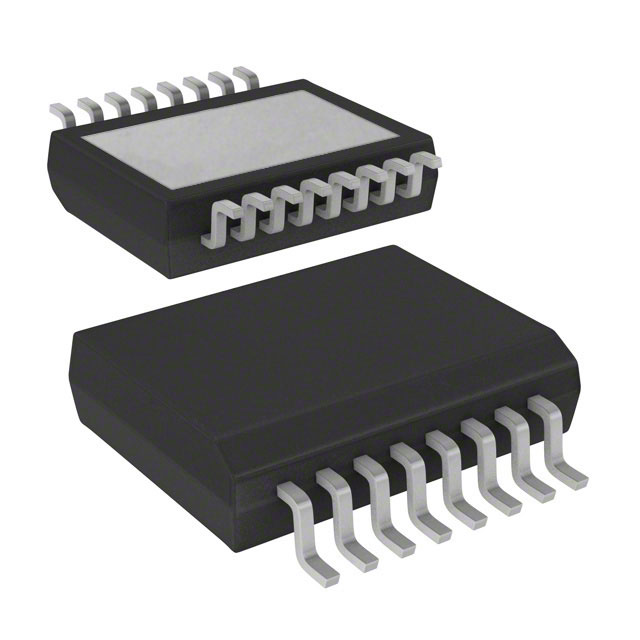
PowerSSO-16
Max transient supply voltage
VCC
40 V
Operating voltage range
VCC
4 to 28 V
Typ. on-state resistance (per Ch)
RON
100 mΩ
Current limitation (typ)
ILIMH
15 A
Stand-by current (max)
ISTBY
0.5 µA
Minimum cranking supply Voltage (VCC decreasing)
VUSD_cranking
2.85 V
•
•
•
•
Product status
VNQ7E100AJ
Product summary
Order code
VNQ7E100AJTR
Package
PowerSSO-16
Packing
Tape and reel
•
AEC-Q100 qualified
Extreme low voltage operation for deep cold cranking applications (compliant
with LV124, revision 2013)
General
–
Quad channel smart high-side driver with CurrentSense analog feedback
–
Very low standby current
–
Compatible with 3 V and 5 V CMOS outputs
CurrentSense diagnostic functions
–
Analog feedback of load current with high precision proportional current
mirror
–
Overload and short to ground (power limitation) indication
–
Thermal shutdown indication
–
OFF-state open-load detection
–
Output short to VCC detection
–
Sense enable/disable
Protections
–
Undervoltage shutdown
–
Overvoltage clamp
–
Load current limitation
–
Self limiting of fast thermal transients
–
Configurable latch-off on overtemperature or power limitation
–
Loss of ground and loss of VCC
–
–
Reverse battery with external components
Electrostatic discharge protection
Applications
•
•
•
Automotive resistive, inductive and capacitive loads
Protected supply for ADAS systems: radars and sensors
Automotive lamps
DS12570 - Rev 3 - February 2019
For further information contact your local STMicroelectronics sales office.
www.st.com
�VNQ7E100AJ
Description
The device is a quad channel high-side driver manufactured using ST proprietary
VIPower® M0-7 technology and housed in a PowerSSO-16 package. The device is
designed to drive 12 V automotive grounded loads through a 3 V and 5 V CMOScompatible interface, providing protection and diagnostics.
The device integrates advanced protective functions such as load current limitation,
overload active management by power limitation and overtemperature shutdown with
configurable latch-off.
A FaultRST pin unlatches the output in case of fault or disables the latch-off
functionality.
A multiplexed current sense pin delivers high precision proportional load current
sense in addition to the detection of overload and short circuit to ground, short to VCC
and off-state openload.
A sense enable pin allows OFF-state diagnosis to be disabled during the module lowpower mode as well as external sense resistor sharing among similar devices.
DS12570 - Rev 3
page 2/45
�VNQ7E100AJ
Block diagram and pin description
1
Block diagram and pin description
Figure 1. Block diagram
VCC
VCC – GND
Clamp
Internal supply
Undervoltage
shut-down
Channel 3
Channel 2
CH 3
Channel 1
CH 2
Control & Diagnostic
Channel 0
CH 1
FaultRST
INPUT3
VCC – OUT
Clamp
INPUT2
CH 0
INPUT1
OUTPUT3
OUTPUT2
INPUT0
Gate Driver
T
SEL1
SEL0
OUTPUT1
Current
Limitation
SEn
Power Limitation
Overtemperature
MUX
CS
0
Short to VCC
Open-Load in OFF
Fault
Current
Sense
VSENSEH
GND
OUTPUT0
GADG1003171112PS
Table 1. Pin functions
Name
VCC
Function
Battery connection.
OUTPUT0,1,2,3 Power output.
DS12570 - Rev 3
GND
Ground connection. Must be reverse battery protected by an external diode / resistor network.
INPUT0,1,2,3
Voltage controlled input pin with hysteresis, compatible with 3 V and 5 V CMOS outputs. They control output
switch state.
CS
Analog current sense output pin delivers a current proportional to the load current.
SEn
Active high, compatible with 3 V and 5 V CMOS outputs input pin; it enables the CS diagnostic pin.
SEL0,1
Active high, compatible with 3 V and 5 V CMOS outputs input pin; They address the CS multiplexer.
FaultRST
Active low, compatible with 3 V and 5 V CMOS outputs input pin; it unlatches the output in case of fault; If
kept low, sets the outputs in auto-restart mode.
page 3/45
�VNQ7E100AJ
Block diagram and pin description
Figure 2. Configuration diagram (top view)
PowerSSO-16
OUTPUT0
1
16
OUTPUT3
SEn
2
15
SEL1
INPUT0
3
14
INPUT3
GND
4
13
CS
FaultRST
5
12
SEL0
INPUT1
6
11
INPUT2
N.C.
7
10
OUTPUT1
8
9
N.C.
OUTPUT2
TAB = V CC
GAPGCFT00632
Table 2. Suggested connections for unused and not connected pins
Connection / pin
CS
N.C.
Output
Input
SEn, SELx, FaultRST
Floating
Not allowed
X (1)
X
X
X
To ground
Through 1 kΩ resistor
X
Not allowed
Through 15 kΩ resistor
Through 15 kΩ resistor
1. X: do not care.
DS12570 - Rev 3
page 4/45
�VNQ7E100AJ
Electrical specification
2
Electrical specification
Figure 3. Current and voltage conventions
IS
VCC
FaultRST
I SEn
I OUT
OUTPUT 0,1,2,3
CS
SEL 0,1
VSEn
V OUT
I SENSE
SE n
I SEL
VFR
VCC
VFn
I FR
VSENSE
I IN
VSEL
INPUT 0,1,2,3
VIN
I GND
GADG0704171646PS
Note:
VFn = VOUTn - VCC during reverse battery condition.
2.1
Absolute maximum ratings
Stressing the device above the rating listed in Table 3. Absolute maximum ratings may cause permanent damage
to the device. These are stress ratings only and operation of the device at these or any other conditions above
those indicated in the operating sections of this specification is not implied. Exposure to the conditions in the table
below for extended periods may affect device reliability.
Table 3. Absolute maximum ratings
Symbol Parameter
Unit
VCC
DC supply voltage
38
-VCC
Reverse DC supply voltage
0.3
VCCPK
Maximum transient supply voltage (ISO 16750-2:2010 Test B clamped to 40 V; RL = 4 Ω)
40
V
VCCJS
Maximum jump start voltage for single pulse short circuit protection
28
V
-IGND
DC reverse ground pin current
200
mA
IOUT
OUTPUT0,1,2,3 DC output current
-IOUT
Reverse DC output current
IIN
ISEn
SEn DC input current
ISEL
SEL0,1 DC input current
IFR
FaultRST DC input current
ISENSE
V
Internally limited
7.5
A
INPUT0,1,2,3 DC input current
CS pin DC output current
(VGND = VCC and VSENSE < 0 V)
CS pin DC output current in reverse (VCC < 0 V)
DS12570 - Rev 3
Value
-1 to 10
mA
-1 to 1.5
mA
10
mA
-20
page 5/45
�VNQ7E100AJ
Thermal data
Symbol Parameter
EMAX
Maximum switching energy (single pulse)
(TDEMAG = 0.4 ms; Tjstart = 150°C)
JEDEC standard (Electrostatic discharge)
VESD
VESD
Tj
Tstg
2.2
Value
Unit
10
mJ
JEDEC 22A-114F
INPUT0,1,2,3
4000
CS, SEn
2000
SEL0,1, FaultRST
4000
OUTPUT0,1,2,3
4000
VCC
4000
Charge device model (CDM-AEC-Q100-011)
750
Junction operating temperature
-40 to 150
Storage temperature
-55 to 150
V
V
°C
Thermal data
Table 4. Thermal data
Symbol
Parameter
Typ. value
Rthj-board
Thermal resistance junction-board (JEDEC JESD 51-5 / 51-8)
Rthj-amb
Thermal resistance junction-ambient (JEDEC JESD 51-5) (1)(3)
60.3
Rthj-amb
Thermal resistance junction-ambient (JEDEC JESD 51-7) (1)(2)
27.1
Rthj-top
Thermal resistance junction-top (JEDEC JESD 51-7)(1)(2)
13.5
(1)(2)
Unit
7.7
°C/W
1. One channel ON.
2. Device mounted on four-layers 2s2p PCB.
3. Device mounted on two-layers 2s0p PCB with 2 cm2 heatsink copper trace.
DS12570 - Rev 3
page 6/45
�VNQ7E100AJ
Main electrical characteristics
2.3
Main electrical characteristics
7 V < VCC < 28 V; -40°C < Tj < 150°C, unless otherwise specified.
All typical values refer to VCC = 13 V; Tj = 25°C, unless otherwise specified.
Table 5. Electrical characteristics during cranking
Symbol
VUSD_Cranking
RON
TTSD (2)
Parameter
Test conditions
Min.
Typ.
Minimum cranking supply
voltage (VCC decreasing)
On-state resistance (1)
IOUT = 0.2 A; VCC = 2.85 V; VCC
decreasing
Shutdown temperature (VCC
decreasing)
VCC =2.85 V
Max.
Unit
2.85
V
300
mΩ
140
°C
1. For each channel.
2. Parameter guaranteed by design and characterization; not subject to production test.
Table 6. Power section
Symbol
Parameter
VCC
Operating supply voltage
VUSD
Undervoltage shutdown
VUSDReset
VUSDhyst
Test conditions
Min.
Typ.
Max.
4
13
28
2.85
Undervoltage shutdown reset
5
Undervoltage shutdown
hysteresis
Vclamp
ISTBY
tD_STBY
IS(ON)
IGND(ON)
DS12570 - Rev 3
On-state resistance (1)
Clamp voltage
Supply current in Standby at
VCC = 13 V (3)
V
0.3
IOUT = 1 A; Tj = 25°C
RON
Unit
100
IOUT = 1 A; Tj = 150°C
210
IOUT = 1 A; VCC = 4 V; Tj = 25°C (2)
160
IS = 20 mA; 25°C < Tj < 150°C
41
IS = 20 mA; Tj = -40°C
38
46
52
mΩ
V
VCC = 13 V;
VIN = VOUT = VFR = VSEn = 0 V;
VSEL0,1 = 0 V; Tj = 25°C
0.5
µA
VCC = 13 V;
VIN = VOUT = VFR = VSEn = 0 V;
VSEL0,1 = 0 V; Tj = 85°C (4)
0.5
µA
VCC = 13 V;
VIN = VOUT = VFR = VSEn = 0 V;
VSEL0,1 = 0 V; Tj = 125°C
3
µA
300
550
µs
10
16
mA
20
mA
Standby mode blanking time
VCC = 13 V
VIN = VOUT = VFR = VSEL0,1 = 0 V;
VSEn = 5 V to 0 V
Supply current
VCC = 13 V; VSEn = VFR = VSEL0,1 = 0 V;
VIN0,1,2,3 = 5 V; IOUT0,1,2,3 = 0 A
Control stage current
consumption in ON state. All
channels active.
VCC = 13 V; VSEn = 5 V;
VFR = VSEL0,1 = 0 V; VIN0,1,2,3 = 5 V;
IOUT0,1,2,3 = 1 A
60
page 7/45
�VNQ7E100AJ
Main electrical characteristics
Symbol
Parameter
Test conditions
Off-state output current at
VCC = 13 V (1)
IL(off)
Output - VCC diode voltage at
Tj = 150°C
VF
Min.
Typ.
Max.
VIN = VOUT = 0 V; VCC = 13 V; Tj = 25°C
0
0.01
0.5
VIN = VOUT = 0 V; VCC = 13 V; Tj = 125°C
0
3
IOUT = -1 A; Tj = 150°C
0.7
Unit
µA
V
1. For each channel.
2. Parameter guaranteed only at Vcc = 4 V and Tj = 25 °C
3. PowerMOS leakage included.
4. Parameter specified by design; not subject to production test.
Table 7. Switching
VCC = 13 V; -40°C < Tj < 150°C, unless otherwise specified
Symbol
Parameter
td(on) (1)
Turn-on delay time at
Tj = 25°C
Test conditions
Turn-on voltage slope at
Tj = 25°C
(dVOUT/dt)on (1)
Max.
10
50
120
10
35
100
0.1
0.3
0.7
Unit
µs
RL = 13 Ω
Turn-off voltage slope at
Tj = 25°C
(dVOUT/dt)off (1)
Typ.
RL = 13 Ω
Turn-off delay time at
Tj = 25°C
td(off) (1)
Min.
V/µs
0.1
0.4
0.7
WON
Switching energy losses at
turn-on (twon)
RL = 13 Ω
—
0.15
0.5 (2)
mJ
WOFF
Switching energy losses at
turn-off (twoff)
RL = 13 Ω
—
0.1
0.5(2)
mJ
RL = 13 Ω
-65
-15
35
µs
Max.
Unit
0.9
V
Differential Pulse skew
tSKEW (1)
(tPHL - tPLH)
1. See Figure 6. Switching times and Pulse skew.
2. Parameter guaranteed by design and characterization, not subject to production test
Table 8. Logic Inputs
7 V < VCC < 28 V; -40°C < Tj < 150°C
Symbol
Parameter
Test conditions
Min.
Typ.
INPUT0,1,2,3 characteristics
VIL
Input low level voltage
IIL
Low level input current
VIH
Input high level voltage
IIH
High level input current
VI(hyst)
Input hysteresis voltage
VICL
Input clamp voltage
VIN = 0.9 V
1
µA
2.1
V
VIN = 2.1 V
10
0.2
IIN = 1 mA
IIN = -1 mA
µA
V
5.3
7.2
-0.7
V
FaultRST characteristics
VFRL
DS12570 - Rev 3
Input low level voltage
0.9
V
page 8/45
�VNQ7E100AJ
Main electrical characteristics
7 V < VCC < 28 V; -40°C < Tj < 150°C
Symbol
Parameter
Test conditions
IFRL
Low level input current
VIN = 0.9 V
VFRH
Input high level voltage
IFRH
High level input current
VFR(hyst)
Input hysteresis voltage
VFRCL
Input clamp voltage
Min.
Typ.
Max.
1
µA
2.1
V
VIN = 2.1 V
10
0.2
IIN = 1 mA
Unit
V
5.3
IIN = -1 mA
µA
7.5
-0.7
V
SEL0,1 characteristics (7 V < VCC < 18 V)
VSELL
Input low level voltage
ISELL
Low level input current
VSELH
Input high level voltage
ISELH
High level input current
VSEL(hyst)
Input hysteresis voltage
VSELCL
Input clamp voltage
0.9
VIN = 0.9 V
1
µA
2.1
V
VIN = 2.1 V
10
0.2
IIN = 1 mA
V
V
5.3
IIN = -1 mA
µA
7.2
-0.7
V
SEn characteristics (7 V < VCC < 18 V)
VSEnL
Input low level voltage
ISEnL
Low level input current
VSEnH
Input high level voltage
ISEnH
High level input current
VSEn(hyst)
Input hysteresis voltage
VSEnCL
Input clamp voltage
0.9
VIN = 0.9 V
1
µA
2.1
V
VIN = 2.1 V
10
0.2
IIN = 1 mA
V
V
5.3
IIN = -1 mA
µA
7.2
-0.7
V
Table 9. Protections
7 V < VCC < 28 V; -40°C < Tj < 150°C
Symbol
Parameter
ILIMH
DC short circuit current
ILIML
Short circuit current during
thermal cycling
TTSD
Shutdown temperature
TR
Reset
TRS
Thermal reset of fault
diagnostic indication
VCC = 13 V
4 V < VCC < 18 V
Thermal hysteresis (TTSD TR)(1)
ΔTJ_SD
Dynamic temperature
Min.
Typ.
Max.
11
15
22
(1)
22
VCC = 13 V; TR < Tj < TTSD
temperature(1)
THYST
DS12570 - Rev 3
Test conditions
VFR = 0 V; VSEn = 5 V;
Unit
A
6
150
175
TRS + 1
TRS + 7
200
°C
135
7
Tj = -40°C; VCC = 13 V
60
K
page 9/45
�VNQ7E100AJ
Main electrical characteristics
7 V < VCC < 28 V; -40°C < Tj < 150°C
Symbol
tLATCH_RST
VDEMAG
Parameter
Test conditions
Fault reset time for output
unlatch(1)
•
Turn-off output voltage clamp
Min.
Typ.
Max.
Unit
3
10
20
µs
VFR = 5 V to 0 V; VSEn = 5 V
E.g. Ch0
VIN0 = 5 V; VSEL0,1 = 0 V
IOUT= 1 A; L = 6 mH; Tj = -40°C
VCC - 38
IOUT= 1 A; L = 6 mH; Tj = 25°C to 150°C
VCC - 41
V
VCC - 46
VCC - 52
V
Max.
Unit
1. Parameter guaranteed by design and characterization; not subject to production test.
Table 10. CurrentSense
7 V < VCC < 18 V; -40°C < Tj < 150°C
Symbol
VSENSE_CL
Parameter
Current sense clamp voltage
Test conditions
Min.
VSEn = 0 V; ISENSE = 1 mA
-17
VSEn = 0 V; ISENSE = -1 mA
Typ.
-12
7
V
Current Sense characteristics
K0
dK0/K0 (1) (2)
K1
dK1/K1 (1) (2)
K2
dK2/K2 (1) (2)
K3
dK3/K3
(1) (2)
ISENSE_OL
IOUT/ISENSE
IOUT = 0.025 A; VSENSE = 0.5 V;
VSEn = 5 V
-30%
Current sense ratio drift
IOUT = 0.025 A; VSENSE = 0.5 V;
VSEn = 5 V
-20
IOUT/ISENSE
IOUT = 0.15 A; VSENSE = 4 V; VSEn = 5 V
-15%
Current sense ratio drift
IOUT = 0.15 A; VSENSE = 4 V; VSEn = 5 V
-10
IOUT/ISENSE
IOUT = 0.7 A; VSENSE = 4 V; VSEn = 5 V
-7%
Current sense ratio drift
IOUT = 0.7 A; VSENSE = 4 V; VSEn = 5 V
-6
IOUT/ISENSE
IOUT = 2 A; VSENSE = 4 V; VSEn = 5 V
-7%
Current sense ratio drift
IOUT = 2 A; VSENSE = 4 V; VSEn = 5 V
-6
CS current for OL detection
IOUT = 0.01 A; VSENSE = 4 V; VSEn = 5 V
Current sense disabled: VSEn = 0 V;
Current sense disabled:
-1 V < VSENSE < 5 V(1)
710
+30%
+20
710
+15%
+10
710
%
+7%
+6
710
%
%
+7%
+6
%
24
µA
0
0.5
-0.5
0.5
0
10
Current sense enabled: VSEn = 5 V All
channels ON; IOUTX = 0 A;
ChX diagnostic selected:
ISENSE0
Current sense leakage
current
•
E.g. Ch0:
VIN0,1,2,3 = 5 V; VSEL0 = 0 V;
VSEL1 = 0 V; IOUT0 = 0 A;
IOUT1,2,3 = 1 A
µA
Current sense enabled: VSEn = 5 V; ChX
OFF;
ChX diagnostic selected:
•
DS12570 - Rev 3
E.g. Ch0:
VIN0 = 0 V; VIN1,2,3 = 5 V; VSEL0 = 0
V; VSEL1 = 0 V; IOUT1,2,3 = 1 A
0
2
page 10/45
�VNQ7E100AJ
Main electrical characteristics
7 V < VCC < 18 V; -40°C < Tj < 150°C
Symbol
Parameter
Test conditions
Min.
Typ.
Max.
Unit
VSEn = 5 V; RSENSE = 2.7 kΩ
VOUT_MSD
(1)
VSENSE_SAT
Output Voltage for Current
sense shutdown
CS saturation voltage
•
E.g. Ch0:
VIN0 = 5 V; VSEL0 = 0 V;
VSEL1 = 0 V; IOUT0 = 1 A
VCC = 7 V; RSENSE = 2.7 kΩ; VSEn = 5 V;
VIN0 = 5 V; VSEL0,1 = 0 V; IOUT0 = 2 A;
5
V
4.8
V
Tj = -40 °C
ISENSE_SAT (1)
IOUT_SAT (1)
CS saturation current
VCC = 7 V; VSENSE = 4 V; VIN0 = 5 V;
VSEn = 5 V; VSEL0,1 = 0 V; Tj = 150 °C
4
mA
Output saturation current
VCC = 7 V; VSENSE = 4 V; VIN0 = 5 V;
VSEn = 5 V; VSEL0,1 = 0 V; Tj = 150 °C
3.1
A
OFF-state diagnostic
VSEn = 5 V; ChX OFF; ChX diagnostic
selected
VOL
OFF-state open-load voltage
detection threshold
IL(off2) (3)
OFF-state output sink current
tDSTKON
OFF-state diagnostic delay
time from falling edge of
INPUT (see
Figure 8. TDSKON )
•
tD_OL_V
Settling time for valid OFFstate open-load diagnostic
indication from rising edge of
SEn
VIN0,1,2,3 = 0 V; VFR = 0 V; VSEL0,1 = 0 V;
VOUT0 = 4 V; VSEn = 0 V to 5 V
•
E.g: Ch0
VIN0 = 0 V; VSEL0,1 = 0 V
VIN = 0 V; VOUT = VOL;
Tj = -40°C to 125°C
2
3
-100
4
V
-15
µA
700
µs
60
µs
30
µs
6.6
V
30
mA
60
µs
20
µs
VSEn = 5 V; ChX ON to OFF transition;
ChX diagnostic selected:
E.g: Ch0
VIN0 = 5 V to 0 V; VSEL0,1 = 0 V;
VOUT0 = 4 V; IOUT0 = 0 A
100
350
VSEn = 5 V; ChX OFF;
tD_VOL
OFF-state diagnostic delay
time from rising edge of VOUT
ChX diagnostic selected:
•
5
E.g: Ch0
VIN0 = 0 V; VSEL0,1 = 0 V;
VOUT0 = 0 V to 4 V
Fault diagnostic feedback (see Table 11. Truth table)
VCC = 13 V; RSENSE = 1 kΩ
VSENSEH
Current sense output voltage
in fault condition
ISENSEH
Current sense output current
in fault condition
•
E.g: Ch0 in open load
VIN0 = 0 V; VSEn = 5 V;
VSEL0,1 = 0 V; IOUT0 = 0 A;
VOUT0 = 4 V
VCC = 13 V; VSENSE = 5 V
5
7
20
Current sense timings (current sense mode - see Figure 7. Current sense timings (current sense mode))(4)
tDSENSE1H
Current sense settling time
from rising edge of SEn
VIN = 5 V; VSEn = 0 V to 5 V;
RSENSE = 1 kΩ; RL = 6.5 Ω
tDSENSE1L
Current sense disable delay
time from falling edge of SEn
VSEn = 5 V to 0 V; RSENSE = 1 kΩ;
RL = 6.5 Ω
DS12570 - Rev 3
5
page 11/45
�VNQ7E100AJ
Main electrical characteristics
7 V < VCC < 18 V; -40°C < Tj < 150°C
Symbol
tDSENSE2H
Parameter
Test conditions
Current sense settling time
from rising edge of INPUT
VIN = 0 V to 5 V; VSEn = 5 V;
RSENSE = 1 kΩ; RL = 6.5 Ω
ΔtDSENSE2H
Current sense settling time
from rising edge of IOUT
(dynamic response to a step
change of IOUT)
tDSENSE2L
Current sense turn-off delay
time from falling edge of
INPUT
Min.
Typ.
Max.
Unit
100
250
µs
100
µs
250
µs
VIN = 5 V; VSEn = 5 V; RSENSE = 1 kΩ;
ISENSE = 90 % of ISENSEMAX; RL = 6.5 Ω
VIN = 5 V to 0 V; VSEn = 5 V;
RSENSE = 1 kΩ; RL = 6.5 Ω
50
Current sense timings (Multiplexer transition times) (4)
tD_XtoY
VIN0 = 5 V; VIN1 = 5 V; VSEn = 5 V; VSEL1
Current sense transition delay
= 0 V; VSEL0 = 0 V to 5 V; IOUT0 = 0 A;
from ChX to ChY
IOUT1 = 1 A; RSENSE = 1 kΩ
20
µs
tD_CStoVSENSEH
Current sense transition delay VIN0 = 5 V; VIN1 = 0 V; VSEn = 5 V; VSEL1
from stable current sense on
= 0 V; VSEL0 = 0 V to 5 V; IOUT0 = 1 A;
ChX to VSENSEH on ChY
VOUT1 = 4 V; RSENSE = 1 kΩ
20
µs
1. Parameter defined by design. Not subject to production test.
2. All values refer to VCC = 13 V; Tj = 25°C, unless otherwise specified.
3. Parameter granted at -40 °C < Tj < 125 °C"
4. Transition delay are measured up to +/- 10% of final conditions.
Figure 4. IOUT/ISENSE versus IOUT
1200
Max
Min
1000
Typ
K-factor
800
600
400
200
0
0
1
IOUT[A]
2
3
GADG0903171157PS
DS12570 - Rev 3
page 12/45
�VNQ7E100AJ
Main electrical characteristics
Figure 5. Current sense accuracy versus IOUT
50
45
40
35
30
Current sense uncalibrated precision
Current sense calibrated precision
% 25
20
15
10
5
0
0
1
2
I OUT [A]
3
GADG0903171216PS
Figure 6. Switching times and Pulse skew
twon
VOUT
twoff
Vcc
80% Vcc
ON
OFF
dVOUT/dt
dVOUT/dt
20% Vcc
t
INPUT
td(off)
td(on)
tpLH
tpHL
t
GAPGCFT00797
DS12570 - Rev 3
page 13/45
�VNQ7E100AJ
Main electrical characteristics
Figure 7. Current sense timings (current sense mode)
IN1
High
SEn
Low
High
SEL0
Low
High
SEL1
Low
IOUT1
Current Sense
tDSENSE2H
tDSENSE1L
tDSENSE1H
tDSENSE2L
GADG0704171311PS
Figure 8. TDSKON
VINPUT
VOUT
VOUT > VOL
MultiSense
TDSTKON
GAPG2609141140CFT
DS12570 - Rev 3
page 14/45
�VNQ7E100AJ
Main electrical characteristics
Table 11. Truth table
Mode
Conditions
Standby
All logic inputs low
INX FR SEn SELX OUTX Current sense
Nominal load connected;
Tj < 150°C
Normal
Overload or short to GND
causing:
Overload
Tj > TTSD or ΔTj > ΔTj_SD
L
L
L
X
H
L
H
Hi-Z
L
See (1)
H
See (1)
Outputs configured for
auto-restart
H
H
See (1)
Outputs configured for
Latch-off
L
X
L
See (1)
H
L
H
See (1)
Output cycles with
temperature hysteresis
H
H
L
See (1)
Output latches-off
L
Hi-Z
Re-start when
VCC > VUSD +
L
Hi-Z
VCC < VUSD (falling)
OFF-state
diagnostics
Short to VCC
L
X
Open-load
L
X
Inductive loads turn-off
L
X
Negative output
voltage
X
X
L
Low quiescent current
consumption
L
Under-voltage
L
Comments
See (1)
See (1)
X
X
H
See
H
See (1)
VOL; MUX channel = channel 0 diagnostic; CS = VSENSEH
DS12570 - Rev 3
page 15/45
�VNQ7E100AJ
Waveforms
2.4
Waveforms
Figure 9. Latch functionality - behavior in hard short-circuit condition (TAMB t latch RST
I limH
Fault Reset
Output
current
Junction temperature


 工商网监
湘ICP备2023018690号
工商网监
湘ICP备2023018690号
