I N D U C T O R S
Inductors for decoupling circuits
Wound ferrite
NLFV-EF series
RoHS
REACH
SVHC-Free
Cl
Br
Pb
Halogen
Free
Lead
Free
NLFV25-EF type
FEATURES
Resin mold type wound inductor for decoupling circuits.
Magnetic shield type containing ferrite powder in the exterior mold resin.
Operating temperature range: –40 to +105°C (including self-temperature rise)
APPLICATION
Smart meters, AV equipment, xDSL, electronic devices for communications infrastructure such as mobile base stations, industrial equipment, other
PART NUMBER CONSTRUCTION
NLFV
25
T
-
Series name
L×W×H dimensions
2.5×2.0×1.8 mm
Packaging style
1R0
M
-
Inductance
(µH)
Inductance
tolerance
EF
Internal code
CHARACTERISTICS SPECIFICATION TABLE
L
(µH)
1
1.5
2.2
3.3
4.7
6.8
10
15
22
33
47
68
100
Tolerance
±20%
±20%
±20%
±20%
±20%
±20%
±10%
±10%
±10%
±10%
±10%
±10%
±10%
L measuring frequency
DC resistance
Rated current
Part No.
(MHz)
7.96
7.96
7.96
7.96
7.96
7.96
2.52
2.52
2.52
2.52
2.52
2.52
0.796
(Ω )±20%
0.07
0.09
0.1
0.2
0.24
0.29
0.36
0.75
1
1.4
1.7
3.3
4
(mA)max.
455
350
315
280
210
175
155
130
105
85
60
50
40
NLFV25T-1R0M-EF
NLFV25T-1R5M-EF
NLFV25T-2R2M-EF
NLFV25T-3R3M-EF
NLFV25T-4R7M-EF
NLFV25T-6R8M-EF
NLFV25T-100K-EF
NLFV25T-150K-EF
NLFV25T-220K-EF
NLFV25T-330K-EF
NLFV25T-470K-EF
NLFV25T-680K-EF
NLFV25T-101K-EF
Measurement equipment
Measurement item
Product No.
L
4294A+16093B
DC resistance
AX-114N
* Equivalent measurement equipment may be used.
Manufacturer
Keysight Technologies
ADEX
Please be sure to request delivery specifications that provide further details on the features and specifications of the products for proper and safe use.
Please note that the contents may change without any prior notice due to reasons such as upgrading.
(1/6)
20180920
inductor_commercial_decoupling_nlfv25-ef_en.fm
�I N D U C T O R S
NLFV25-EF type
L FREQUENCY CHARACTERISTICS
1000
100
101K
680K
470K
330K
Inductance(µH)
220K
150K
10 100K
6R8M
4R7M
3R3M
2R2M
1R5M
1
1R0M
0.1
0.1
1
10
100
Frequency(MHz)
Measurement equipment
Product No.
Manufacturer
4294A
Keysight Technologies
* Equivalent measurement equipment may be used.
Please be sure to request delivery specifications that provide further details on the features and specifications of the products for proper and safe use.
Please note that the contents may change without any prior notice due to reasons such as upgrading.
(2/6)
20180920
inductor_commercial_decoupling_nlfv25-ef_en.fm
�I N D U C T O R S
NLFV25-EF type
INDUCTANCE VS. DC BIAS CHARACTERISTICS
1000
100
101K
680K
470K
330K
Inductance(µH)
220K
150K
10
100K
6R8M
4R7M
3R3M
2R2M
1R5M
1
1R0M
0.1
0.01
0.1
1
10
DC current(A)
Measurement equipment
Product No.
Manufacturer
4285A+42841A+42842C
Keysight Technologies
* Equivalent measurement equipment may be used.
Please be sure to request delivery specifications that provide further details on the features and specifications of the products for proper and safe use.
Please note that the contents may change without any prior notice due to reasons such as upgrading.
(3/6)
20180920
inductor_commercial_decoupling_nlfv25-ef_en.fm
�I N D U C T O R S
NLFV25-EF type
IMPEDANCE VS. FREQUENCY CHARACTERISTICS
100000
101K
680K
470K
330K
220K
10000
150K
100K
6R8M
4R7M
3R3M
2R2M
1R5M
1000
Impedance(Ω)
1R0M
100
10
1
0.1
0.1
1
10
Frequency(MHz)
100
1000
Measurement equipment
Product No.
Manufacturer
4294A
Keysight Technologies
* Equivalent measurement equipment may be used.
Please be sure to request delivery specifications that provide further details on the features and specifications of the products for proper and safe use.
Please note that the contents may change without any prior notice due to reasons such as upgrading.
(4/6)
20180920
inductor_commercial_decoupling_nlfv25-ef_en.fm
�I N D U C T O R S
NLFV25-EF type
SHAPE & DIMENSIONS
PACKAGING STYLE
REEL DIMENSIONS
2±0.1
1.4±0.1
2.0±0.5
0.55
(0.4)
(1.7)
(0.4)
1.8±0.1
ø60
2.5±0.2
0.5
(1.0)
Dimensions in mm
ø13.0±0.5
9
ø21.0±0.8
13
ø180
Dimensions in mm
1.5 +0.1
–0
2.00±0.05
4.00±0.10
B
1.5
8.00±0.30
Sprocket
hole
0.4
3.50±0.05
RECOMMENDED LAND PATTERN
1.75±0.1
TAPE DIMENSIONS
1.0
1.5
1.0
A
K
Dimensions in mm
Cavity
4.00±0.10
Dimensions in mm
Type
NLFV25-EF
Package quantity
Soldering
Natural
cooling
255°C
Temperature
K
2
230°C
2000 pcs/reel
TEMPERATURE RANGE, INDIVIDUAL WEIGHT
Peak
230°C
B
2.7
PACKAGE QUANTITY
RECOMMENDED REFLOW PROFILE
Preheating
A
2.3
Operating
Storage
Individual
temperature range
temperature range
weight
–40 to +105 °C
–40 to +105 °C
25 mg
Operating temperature range includes self-temperature rise.
The storage temperature range is for after the assembly.
180°C
10s max.
150°C
90 to 120s
40s
Time
Please be sure to request delivery specifications that provide further details on the features and specifications of the products for proper and safe use.
Please note that the contents may change without any prior notice due to reasons such as upgrading.
(5/6)
20180920
inductor_commercial_decoupling_nlfv25-ef_en.fm
�I N D U C T O R S
REMINDERS FOR USING THESE PRODUCTS
Before using these products, be sure to request the delivery specifications.
SAFETY REMINDERS
Please pay sufficient attention to the warnings for safe designing when using this products.
REMINDERS
The storage period is less than 6 months. Be sure to follow the storage conditions (temperature: 5 to 40°C, humidity: 10 to 75% RH or
less).
If the storage period elapses, the soldering of the terminal electrodes may deteriorate.
Do not use or store in locations where there are conditions such as gas corrosion (salt, acid, alkali, etc.).
Before soldering, be sure to preheat components.
The preheating temperature should be set so that the temperature difference between the solder temperature and chip temperature
does not exceed 150°C.
Soldering corrections after mounting should be within the range of the conditions determined in the specifications.
If overheated, a short circuit, performance deterioration, or lifespan shortening may occur.
When embedding a printed circuit board where a chip is mounted to a set, be sure that residual stress is not given to the chip due to
the overall distortion of the printed circuit board and partial distortion such as at screw tightening portions.
Self heating (temperature increase) occurs when the power is turned ON, so the tolerance should be sufficient for the set thermal
design.
Carefully lay out the coil for the circuit board design of the non-magnetic shield type.
A malfunction may occur due to magnetic interference.
Use a wrist band to discharge static electricity in your body through the grounding wire.
Do not expose the products to magnets or magnetic fields.
Do not use for a purpose outside of the contents regulated in the delivery specifications.
The products listed on this catalog are intended for use in general electronic equipment (AV equipment, telecommunications equipment, home appliances, amusement equipment, computer equipment, personal equipment, office equipment, measurement equipment, industrial robots) under a normal operation and use condition.
The products are not designed or warranted to meet the requirements of the applications listed below, whose performance and/or quality require a more stringent level of safety or reliability, or whose failure, malfunction or trouble could cause serious damage to society,
person or property.
If you intend to use the products in the applications listed below or if you have special requirements exceeding the range or conditions
set forth in the each catalog, please contact us.
(1) Aerospace/aviation equipment
(2) Transportation equipment (cars, electric trains, ships, etc.)
(3) Medical equipment
(4) Power-generation control equipment
(5) Atomic energy-related equipment
(6) Seabed equipment
(7) Transportation control equipment
(8) Public information-processing equipment
(9) Military equipment
(10) Electric heating apparatus, burning equipment
(11) Disaster prevention/crime prevention equipment
(12) Safety equipment
(13) Other applications that are not considered general-purpose
applications
When designing your equipment even for general-purpose applications, you are kindly requested to take into consideration securing protection circuit/device or providing backup circuits in your equipment.
Please be sure to request delivery specifications that provide further details on the features and specifications of the products for proper and safe use.
Please note that the contents may change without any prior notice due to reasons such as upgrading.
(6/6)
20180920
inductor_commercial_decoupling_nlfv25-ef_en.fm
�
很抱歉,暂时无法提供与“NLFV25T-220K-EF”相匹配的价格&库存,您可以联系我们找货
免费人工找货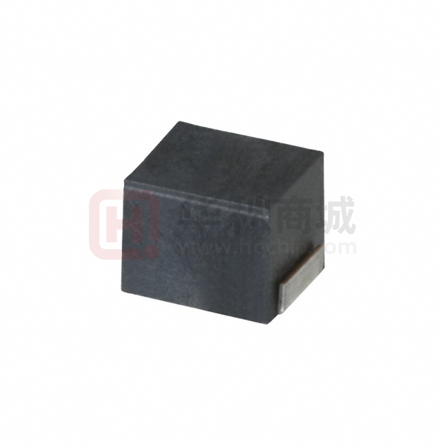


 工商网监
湘ICP备2023018690号
工商网监
湘ICP备2023018690号

