TL431
Precision adjustable shunt regulator
Device Descripsion
K
The TL431 is a three-terminal adjustable shunt regulator
A
offering excellent temperature stability. This. device has a typical
dynamic output impedance of 0.2Ω. The device can be used as a
replacement for zener diodes in many applications.
R
R
A
TO--92
K
R
A
K
SOT-89
FEATURES
Applications
Shunt Regulator
High-Current Shunt Regulator
Precision Current Limiter
or
7
3
6
4
5
ct
8
2
REF
ANODE
ANODE
NC
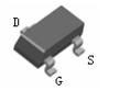
SOT-23
A
R
K
FUNCTIONAL BLOCK DIAGRAM
em
SYMBOL
1
MI
CR
O
S
z
z
z
ic
factor in the whole temperature scope is 50 ppm/℃
CATHODE
ANODE
ANODE
NC
du
z
SOP-8
The output voltage can be adjusted to 36V
Low dynamic output impedance, its typical value is 0.2Ω
Trapping current capability is 1 to 100mA
Low output noise voltage
Fast on -state response
The effective temperature compensation in the working range of
full temperature
The typical value of the equivalent temperature
on
z
z
z
z
z
z
JS
Limiting Values (Absolute Maximum Rating)
Parameter
Symbol
Value
Unit
Cathode Voltage
VKA
37
V
Cathode Current Range (Continuous)
IKA
-100~+150
mA
Reference lnput Current Range
Iref
0.05~+10
mA
Power Dissipation
PD
300
mW
Thermal Resistance from Junction
to Ambient
RθJA
417
℃/W
Operating Junction Temperature
Tj
150
℃
Operating Ambient Temperature Range
Topr
-25~+85
℃
Tstg
-65~+150
℃
Storage temperature Range
www.jsmsemi.com
第1/8页
�TL431
Precision adjustable shunt regulator
Electrical Characteristics (TA=25℃ unless otherwise noted)
Symbol
Deviation of reference input voltage
over temperature (note) (Fig.1)
Vref
VKA=VREF, IKA=10mA
△Vref /△T
VKA =VREF, IKA =10mA
TMIN≤Ta≤TMAX
△Vref /△VKA
IKA=10mA
voltage (Fig.2)
Minimum cathode current for
Dynamic impedance
du
R2=∞
TA=-25 to 85℃
VKA=VREF
VKA=36V,VREF=0
IKA(OFF)
VKA=VREF, lKA=1 to 100mA
f≤1.0kHz
em
MI
CR
JS
△lref /△T
VKA
17
mV
-1.0
-2.7
mV/V
-0.5
-2.0
mV/V
1.5
4
μA
0.4
1.2
μA
0.45
1.0
mA
0.05
1.0
μA
0.15
0.5
Ω
��������1%
2.475-2.525
2.487-2.513
Figure 1. Test Circuit for VKA = Vref
Vref
4.5
��� 0.5%
Range
IK
V
O
S
Note: TMIN=-25℃ ,TMAX=+85℃
Rank
2.525
lKA=10mA, R1=10kΩ
ZKA
CLASSIFICATION RI Vref
2.5
ic
Off-state cathode Current (Fig.3)
Input
R2=∞
IKA(min)
regulation (Fig.1)
2.475
on
over full temperature range (Fig.2)
Unit
△VKA
IKA= 10mA,R1=10kΩ
lref
Deviation Of reference input current
Max
=10V~VREF
=36V~ 10V
Reference input current (Fig.2)
Typ
△VKA
Ratio of change in reference input
voltage to the change in cathode
Min
or
Reference input voltage (Fig.1)
conditions
Test
ct
Parameter
Figure 2. Test Circuit for VKA > Vref
VKA
Input
R1
Iref
R2
Input
Ioff
IK
V
KA
Figure 3. Test Circuit for Ioff
VKA
ǒ Ǔ
+ Vref 1 ) R1
) Iref S R1
R2
Vref
www.jsmsemi.com
第2/8页
�TL431
Precision adjustable shunt regulator
Typical Characteristics
Cathode Voltage
100
or
50
0
ct
IK, CATHODE CURRENT
(mA)
150
-50
VKA=Vref
Ta=25℃
-1
0
1
2
VKA, CATHODE VOLTAGE
3
(V)
Cathode Current versus
Cathode Voltage
800
IKA(min)
em
400
300
200
100
0
ref
VKA=Vref
-100
Ta=25℃
-0.5
0.0
0.5
1.0
1.5
MI
CR
-200
-1.0
KA
KA
ic
600
O
S
IK, CATHODE CURRENT
(uA)
700
500
du
-2
on
-100
2.0
2.5
3.0
(V)
Test Circuit for VKA=Vref
JS
VKA, CATHODE VOLTAGE
www.jsmsemi.com
第3/8页
�TL431
Precision adjustable shunt regulator
Typical Characteristics
Change in Reference Input
Voltage versus Cathode Voltage
0
(mV)
IK=10mA
Ta=25℃
△Vref, REFERENCE INPUT VOLTAGE
-4
or
-8
ct
-12
-16
-20
10
15
20
25
VKA, CATHODE VOLTAGE
40
em
500
400
200
100
O
S
300
0
-40
IK=10mA
R1=10KΩ
-20
0
20
40
60
Ta, AMBIENT TEMPERATURE
80
100
Test Circuit for Iref
(℃ )
Off-State Cathode Current
versus Ambient Temperature
Ioff, OFF-STATE CATHODE CURRENT
(nA)
JS
50
Test Circuit for VKA=Vref(1+R1/R2)+R1*Iref
ic
600
MI
CR
(nA)
35
(V)
Reference Input Current versus
Ambient Temperature
700
Iref, REFERENCE INPUT CURRENT
30
du
5
on
0
45
40
35
30
25
20
15
10
VKA=36V
5
0
-40
Vref=0V
-20
0
20
40
Ta, AMBIENT TEMPERATURE
60
80
100
Test Circuit for Ioff
(℃ )
www.jsmsemi.com
第4/8页
�TL431
Precision adjustable shunt regulator
Package Outline Dimensions
SOT-23
Suggested Pad Layout
JS
MI
CR
O
S
em
ic
on
du
ct
or
SOT-23
www.jsmsemi.com
第5/8页
�TL431
Precision adjustable shunt regulator
Package Outline Dimensions
JS
M
IC
RO
Se
mi
co
nd
uc
to
r
TO-92
Symbol
A
A1
b
c
D
D1
E
e
e1
L
Φ
h
Dimensions In Millimeters
Min
Max
3.300
3.700
1.100
1.400
0.380
0.550
0.360
0.510
4.400
4.700
3.430
4.300
4.700
1.270 TYP
2.440
2.640
14.100
14.500
1.600
0.000
0.380
www.jsmsemi.com
Dimensions In Inches
Min
Max
0.130
0.146
0.043
0.055
0.015
0.022
0.014
0.020
0.173
0.185
0.135
0.169
0.185
0.050 TYP
0.096
0.104
0.555
0.571
0.063
0.000
0.015
第6/8页
�TL431
Precision adjustable shunt regulator
Package Outline Dimensions
IC
RO
Se
mi
co
nd
uc
to
r
SOT-89
Symbol
JS
M
A
b
b1
c
D
D1
E
E1
e
e1
L
Dimensions In Millimeters
Min
Max
1.400
1.600
0.320
0.520
0.400
0.580
0.350
0.440
4.400
4.600
1.550 REF
2.300
2.600
3.940
4.250
1.500 TYP
3.000 TYP
0.900
1.200
www.jsmsemi.com
Dimensions In Inches
Min
Max
0.055
0.063
0.013
0.197
0.016
0.023
0.014
0.017
0.173
0.181
0.061 REF
0.091
0.102
0.155
0.167
0.060TYP
0.118TYP
0.035
0.047
第7/8页
�TL431
Precision adjustable shunt regulator
Package Outline Dimensions
IC
RO
Se
mi
co
nd
uc
to
r
SOP-8
Symbol
JS
M
A
A1
A2
b
c
D
E
E1
e
L
θ
Dimensions In Millimeters
Min
Max
1.350
1.750
0.100
0.250
1.350
1.550
0.330
0.510
0.170
0.250
4.700
5.100
3.800
4.000
5.800
6.200
1.270(BSC)
0.400
1.270
0°
8°
www.jsmsemi.com
Dimensions In Inches
Min
Max
0.053
0.069
0.004
0.010
0.053
0.061
0.013
0.020
0.006
0.010
0.185
0.200
0.150
0.157
0.228
0.244
0.050(BSC)
0.016
0.050
0°
8°
第8/8页
�
很抱歉,暂时无法提供与“TL431”相匹配的价格&库存,您可以联系我们找货
免费人工找货- 国内价格
- 10+0.13600
- 50+0.12580
- 200+0.11730
- 600+0.10880
- 1500+0.10200
- 3000+0.09775


 工商网监
湘ICP备2023018690号
工商网监
湘ICP备2023018690号
