JIANGSU CHANGJING ELECTRONICS TECHNOLOGY CO., LTD
PDFN:%5×6-8L-B Plastic-Encapsulate MOSFETS
CJAC100SN08U
N-Channel Power MOSFET
V(BR)DSS
RDS(on)TYP
ID
80 V
3.0mΩ@10V
100A
PDFN:%5×6-8L-B
DESCRIPTION
These N-Channel enhancement mode power field effect transistors are
using SGT technology.This advanced technology has been especially
tailored to minimize on-state resistance, provide superior switching
performance, and withstand high energy pulse in the avalanche and
commutation mode.These devices are well suited for high efficiency
fast switching applications.
FEATURES
Battery switch
Good stability and uniformity with high EAS
Load switch
High density cell design for ultra low RDS(ON)
Excellent package for good heat
dissipation
LED applications
APPLICATIONS
Networking
Load Switch
EQUIVALENT CIRCUIT
MARKING
8
D
7
D
6
D
5
D
CJAC100SN08U = Part No.
CJAC
100SN08U
XX
Solid dot=Pin1 indicator.
XX=Code.
2
1
S
3
S
4
S
G
PIN 1
MAXIMUM RATINGS ( Ta=25℃ unless otherwise noted )
Parameter
Symbol
Limit
Unit
Drain-Source Voltage
VDS
80
V
Gate-Source Voltage
VGS
±20
V
Continuous Drain Current
ID
①
100
A
Pulsed Drain Current
IDM②
300
A
Single Pulsed Avalanche Energy
EAS③
500
mJ
Power Dissipation
PD①
104
W
Thermal Resistance from Junction to Ambient
RθJA⑥
62.5
℃/W
Thermal Resistance from Junction to Case
RθJC①
1.2
℃/W
-55~+150
℃
TJ ,Tstg
Operating Junction and Storage Temperature Range
www.jscj-elec.com
1
Rev. - 1.1
�MOSFET ELECTRICAL CHARACTERISTICS
Ta =25 ℃ unless otherwise specified
Parameter
Symbol
Test Condition
Min
Typ
Max
Unit
80
-
-
V
TJ =25℃
-
-
1.0
TJ =125℃
-
-
100
Off characteristics
Drain-source breakdown voltage
V(BR) DSS
VGS = 0V, ID =1mA
Zero gate voltage drain current
IDSS
VDS =64V,
VGS =0V
Gate-body leakage current
IGSS
VDS =0V, VGS =±20V
-
-
±100
nA
Gate-threshold voltage
VGS(th)
VDS =VGS, ID =250µA
2.0
2.8
4.0
V
Static drain-source on-sate resistance
RDS(on)
VGS =10V, ID =30A
-
3.0
3.9
mΩ
VGS =6V, ID =30A
-
4.0
6.0
mΩ
-
3780
-
-
1800
-
-
25
-
-
2.5
-
-
60
-
-
14
-
On characteristics
µA
④
Dynamic characteristics ④ ⑤
Input capacitance
Ciss
Output capacitance
Coss
Reverse transfer capacitance
Crss
Gate resistance
Rg
Switching characteristics
VDS =30V,VGS =0V,
f =500kHz
f =1MHz
pF
Ω
④⑤
Total gate charge
Qg
Gate-source charge
Qgs
Gate-drain charge
Qgd
-
14
-
Turn-on delay time
td(on)
-
68
-
VDS=40V, VGS=10V,
-
82
-
RL=2Ω
-
168
-
-
80
-
-
-
1.2
V
①
-
-
100
A
②
-
-
300
A
Turn-on rise time
Turn-off delay time
Turn-off fall time
VGS=10V, VDS=20V,
ID=20A
tr
td(off)
tf
nC
ns
Drain-Source Diode Characteristics
Drain-source diode forward voltage
Continuous drain-source diode forward
current
Pulsed drain-source diode forward current
VSD
IS
ISM
④
VGS =0V, IS=10A
Notes:
1.TC=25℃ Limited only by maximum temperature allowed.
2.PW≤10μs, Duty cycle≤1%.
3.EAS condition: VDD=30V,VGS=10V, L=0.5mH, Rg=25Ω Starting TJ = 25°℃.
4.Pulse Test : Pulse Width≤300µs, duty cycle ≤2%.
5.Guaranteed by design, not subject to production.
6.The value of RθJA is measured with the device mounted on 1 in 2 FR-4 board with 2oz. Copper, in a still air environment with Ta=25 ℃.
www.jscj-elec.com
2
Rev. - 1.1
�Typical Characteristics
Transfer Characteristics
Output Characteristics
100
100
TJ=25℃
Pulsed
VGS=10V,8V,6V,5V
Pulsed
(A)
80
(A)
80
DRAIN CURRENT
60
ID
VGS=4.5V
ID
DRAIN CURRENT
VDS=17V
40
20
60
TJ=25℃
40
20
VGS=4V
0
0
1
3
DRAIN TO SOURCE VOLTAGE
0
4
VDS
0
2
(V)
4
6
GATE TO SOURCE VOLTAGE
VGS
8
(V)
RDS(ON)—— VGS
RDS(ON) —— ID
8
12
TJ=25℃
ID=30A
Pulsed
Pulsed
(m)
RDS(ON)
VGS= 6V
ON-RESISTANCE
ON-RESISTANCE
RDS(ON)
(m)
10
6
4
VGS= 10V
2
8
TJ=125℃
6
4
TJ=25℃
2
0
10
20
30
DRAIN CURRENT
40
ID
0
50
0
(A)
2
4
6
8
GATE TO SOURCE VOLTAGE
IS —— VSD
10
VGS
Threshold Voltage
4
80
Pulsed
(V)
3
VTH
10
TJ=125℃
THRESHOLD VOLTAGE
IS (A)
Pulsed
SOURCE CURRENT
12
(V)
TJ=25℃
1
0.1
1
0.2
SOURCE TO DRAIN VOLTAGE
www.jscj-elec.com
2
1
0
25
2
VSD (V)
50
75
JUNCTION TEMPERATURE
3
100
TJ
125
(℃ )
Rev. - 1.1
�Typical Characteristics
Gate Charge
Capacitances
10000
10
VDS=20V
Ciss
(V)
ID =20A
f=500kHz
Pulsed
Coss
8
GATE TO SOURCE VOLTAGE
C (pF)
VGS
1000
Pulsed
CAPACITANCE
100
Crss
10
1
0.1
0.1
1
DRAIN TO SOURCEVOLTAGE
4
2
0
40
10
6
0
10
VDS (V)
20
30
40
50
GATE CHARGE (nC)
NORMALIZED TRAISIENT THERMAL IMPENDANCE
NORMALIZED THERMAL IMPEDENCE, Zthjc (K/W)
10
In descending order
D=0.5, 0.2, 0.1, 0.05, 0.02, 0.01, Single Pulse
1
D=TON/T
0.1
TJ,PK=TC+PDM×RθJC
0.01
1E-6
1E-5
1E-4
1E-3
0.01
0.1
SQUARE WAVE PULSE DURATION, tp (sec)
MAXIMUM FORWARD BIASED SAFE OPERATING AREA
600
IDM
100
10us
DRAIN CURRENT
ID
(A)
n
So
RD
1us
d
ite
Lim
100us
10
1ms
10ms
DC
1
RθJC=1.2℃/W
TC=25℃
Single pulse
0.1
0.1
BVdss
1
10
DRAIN TO SOURCE VOLTAGE
www.jscj-elec.com
100
VDS
300
(V)
4
Rev. - 1.1
�Symbol
A
A3
D
E
D1
E1
D2
E2
k
b
e
L
L1
H
θ
www.jscj-elec.com
5
Dimensions In Millimeters
Min.
Max.
1.100
0.900
0.254REF.
4.800
5.100
5.874
6.126
3.910
4.110
3.375
3.575
4.800
5.000
5.674
5.826
1.625
1.190
0.350
0.450
1.270TYP.
0.550
0.750
0.300
0.700
0.550
0.750
8°
12°
Dimensions In Inches
Min.
Max.
0.043
0.035
0.010REF.
0.201
0.188
0.231
0.241
0.154
0.162
0.133
0.141
0.188
0.197
0.223
0.229
0.047
0.064
0.014
0.018
0.050TYP.
0.030
0.022
0.012
0.028
0.022
0.030
8°
12°
Rev. - 1.1
�www.jscj-elec.com
5
Rev. - 1.1
�
很抱歉,暂时无法提供与“CJAC100SN08U”相匹配的价格&库存,您可以联系我们找货
免费人工找货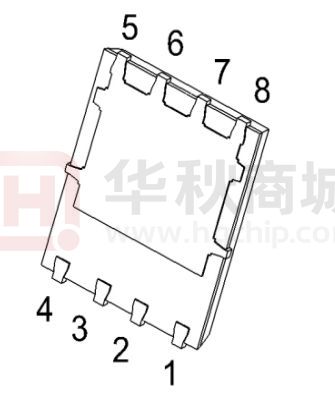


 工商网监
湘ICP备2023018690号
工商网监
湘ICP备2023018690号
